instrument panel Seat Leon 5D 2012 Owner's manual
[x] Cancel search | Manufacturer: SEAT, Model Year: 2012, Model line: Leon 5D, Model: Seat Leon 5D 2012Pages: 289, PDF Size: 3.81 MB
Page 33 of 289
32Airbag system
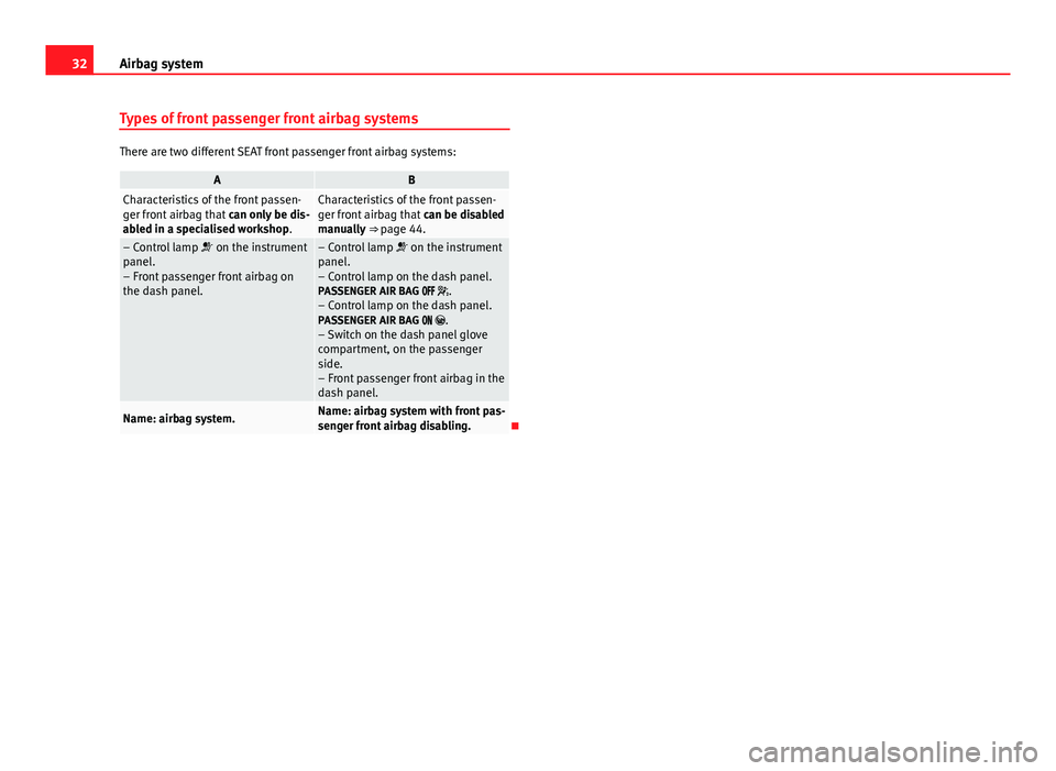
Types of front passenger front airbag systems
There are two different SEAT front passenger front airbag systems:
ABCharacteristics of the front passen-
ger front airbag that can only be dis-
abled in a specialised workshop.Characteristics of the front passen-
ger front airbag that can be disabled
manually ⇒ page 44.
– Control lamp on the instrument
panel.
– Front passenger front airbag on
the dash panel.– Control lamp on the instrument
panel.
– Control lamp on the dash panel.
PASSENGER AIR BAG .
– Control lamp on the dash panel. PASSENGER AIR BAG .
– Switch on the dash panel glove
compartment, on the passenger
side.
– Front passenger front airbag in the
dash panel.
Name: airbag system.Name: airbag system with front pas-
senger front airbag disabling.
Page 34 of 289

33
Airbag system
Control lamp
Fig. 16 Control lamp for
disabling the front pas-
senger front airbag on
the dash panel
lights upDigitPossible causeSolution
Instrument panelFault in airbag system and seat belt tensioners.Have the system checked immediately by a specialised
workshop.
Dash panelFault in the airbag system.Have the system checked immediately by a specialised
workshop.
Front passenger front airbag disabled.Check whether the airbag should remain disabled.
Dash panelFront passenger front airbag enabled.No solution. The control lamp switches off about 60 sec-
onds after ignition is turned on or after enabling of the
front passenger front airbag with the key lock switch.
Several warning and control lamps should light up for a few seconds when
the ignition is switched on, signalling that the function is being verified.
They will switch off after a few seconds.
If the PASSENGER AIR BAG control lamp does not remain lit or if it is lit
together with the control lamp on the instrument panel and the front pas-
senger front airbag is disabled, there may be a fault in the airbag system
⇒
.
Safety FirstOperating instructionsPractical TipsTechnical specifications
Page 60 of 289
59
Controls and displays
Operating instructions Controls and displays
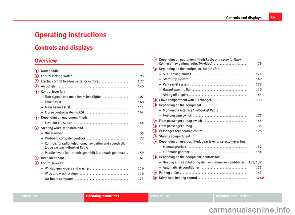
Overview
Door handle
Central locking switch . . . . . . . . . . . . . . . . . . . . . . . . . . . . . . . . . . . . . 93
Electric control to adjust exterior mirrors . . . . . . . . . . . . . . . . . . . .122
Air outlets . . . . . . . . . . . . . . . . . . . . . . . . . . . . . . . . . . . . . . . . . . . . . . . . 140
Control lever for:
– Turn signals and main beam headlights . . . . . . . . . . . . . . . . .107
– Lane Assist . . . . . . . . . . . . . . . . . . . . . . . . . . . . . . . . . . . . . . . . . . . . . 168
– Main beam assist . . . . . . . . . . . . . . . . . . . . . . . . . . . . . . . . . . . . . . . 111
– Cruise control system (CCS) . . . . . . . . . . . . . . . . . . . . . . . . . . . . . 164
Depending on equipment fitted:
– Lever for cruise control . . . . . . . . . . . . . . . . . . . . . . . . . . . . . . . . . . 164
Steering wheel with horn and
– Driver airbag . . . . . . . . . . . . . . . . . . . . . . . . . . . . . . . . . . . . . . . . . . . 35
– On-board computer controls . . . . . . . . . . . . . . . . . . . . . . . . . . . . 73
– Controls for radio, telephone, navigation and speech dia-
logue system ⇒ Booklet Radio
– Paddle levers for tiptronic gearshift (automatic gearbox) . .159
Instrument panel . . . . . . . . . . . . . . . . . . . . . . . . . . . . . . . . . . . . . . . . . . 61
Control lever for:
– Windscreen wipers and washer . . . . . . . . . . . . . . . . . . . . . . . . . . 116
– Wipe and wash system . . . . . . . . . . . . . . . . . . . . . . . . . . . . . . . . . 116
– On-board computer . . . . . . . . . . . . . . . . . . . . . . . . . . . . . . . . . . . . . 73
12345
6
7
89
Depending on equipment fitted: Radio or display for Easy
Connect (navigation, radio, TV/video)
. . . . . . . . . . . . . . . . . . . . . .79
Depending on the equipment, buttons for:
– SEAT driving modes . . . . . . . . . . . . . . . . . . . . . . . . . . . . . . . . . . . . . 171
– Start-Stop system . . . . . . . . . . . . . . . . . . . . . . . . . . . . . . . . . . . . . . . 149
– Park assist system . . . . . . . . . . . . . . . . . . . . . . . . . . . . . . . . . . . . . . 178
– Hazard warning lights . . . . . . . . . . . . . . . . . . . . . . . . . . . . . . . . . . 110
– Airbag off display . . . . . . . . . . . . . . . . . . . . . . . . . . . . . . . . . . . . . . . 45
Glove compartment with CD changer. . . . . . . . . . . . . . . . . . . . . . .130
Depending on the equipment:
– Multimedia interface* ⇒ Booklet Radio
– Tyre pressure switch . . . . . . . . . . . . . . . . . . . . . . . . . . . . . . . . . . . . 177
Front passenger airbag switch . . . . . . . . . . . . . . . . . . . . . . . . . . . . . 45
Front passenger airbag . . . . . . . . . . . . . . . . . . . . . . . . . . . . . . . . . . . . 35
Passenger seat heating control . . . . . . . . . . . . . . . . . . . . . . . . . . . . 126
Storage compartment
Depending on gearbox fitted, gear lever or selector lever for:
– manual gearbox . . . . . . . . . . . . . . . . . . . . . . . . . . . . . . . . . . . . . . . . 152
– automatic gearbox . . . . . . . . . . . . . . . . . . . . . . . . . . . . . . . . . . . . . . 154
Depending on the equipment, controls for:
– Heating and ventilation system or manual air conditioner .138, 137
– Automatic air conditioner . . . . . . . . . . . . . . . . . . . . . . . . . . . . . . . 135
Parking brake . . . . . . . . . . . . . . . . . . . . . . . . . . . . . . . . . . . . . . . . . . . . . 147
Driver seat heating control . . . . . . . . . . . . . . . . . . . . . . . . . . . . . . . . . 126
10
11
1213
1415161718
19
2021
Safety FirstOperating instructionsPractical TipsTechnical specifications
Page 62 of 289

61
Instruments and warning/control lamps
Instruments and warning/control lamps
Instruments Introduction
Additional information and warnings:
● Control and warning lamps ⇒ page 69
● SEAT information system
● Easy Connect system
● Gear engaged display (automatic gearbox) ⇒ page 154.
● Instructions for inspection intervals ⇒ Booklet Maintenance Programme
WARNING
Any distraction may lead to an accident, with the risk of injury.
● Do not operate the instrument panel controls when driving.
View of instrument panelFig. 36 Instrument panel, on dash panel
Details of the instruments
⇒ Fig. 36:
Rev counter (with the engine running, in hundreds of revolutions per
minute).
The beginning of the red zone of the rev counter indicates the maxi-
mum speed in any gear after running-in and with the engine hot. How-
ever, it is advisable to change up a gear or move the selector lever to D
(or lift your foot off the accelerator) before the needle reaches the red
zone ⇒
.
Engine coolant temperature display
⇒ page 215.
Displays on the screen
⇒ page 62.
Adjuster button and display ⇒ page 67
Speedometer.
Fuel reserve display
⇒ page 207.
123456
Safety FirstOperating instructionsPractical TipsTechnical specifications
Page 63 of 289

62Instruments and warning/control lamps
CAUTION
● To prevent damage to the engine, the rev counter needle should only re-
main in the red zone for a short period of time.
● When the engine is cold, avoid high revs and heavy acceleration and do
not make the engine work hard.
For the sake of the environment
Changing up a gear in time reduces fuel consumption and noise.
Displays on screen
Fig. 37 A: bonnet open; B: rear lid open; C: front left door open; D: rear right door
open (4-door vehicles only)
A variety of information can be viewed on the instrument panel display
⇒ Fig. 36 3
, depending on the vehicle equipment: ●
Bonnet, rear lid and doors open ⇒ Fig. 37.
● Information and warning texts
● Mileage
● Time
● Navigation instructions
● Outside temperature
● Compass
● Selector lever position ⇒ page 154
● Recommended gear (manual gearbox) ⇒ page 68
● Multifunction display (MFD) and menus with different setting options
⇒ page 73.
● Service interval display ⇒ page 65
● Second speed display ⇒ page 73
● Speed warning function ⇒ page 149
● Start-Stop system status display ⇒ page 149
● Identifying letters on engine (MKB)
Bonnet, rear lid and doors open
When the ignition is switched on or when driving, the bonnet, rear lid or
doors that are open will be indicated on the instrument panel display, and if
it should be the case, this will also be indicated audibly. The display may
vary according to the type of instrument panel fitted.
Page 64 of 289
63
Instruments and warning/control lamps
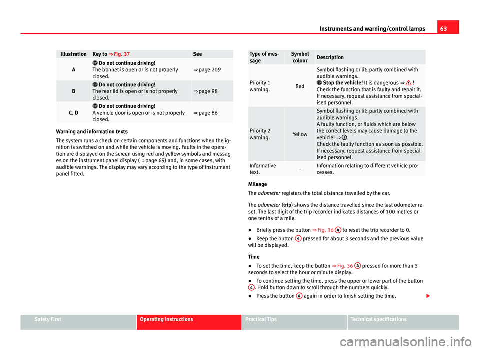
IllustrationKey to ⇒ Fig. 37See
A Do not continue driving!
The bonnet is open or is not properly
closed.⇒ page 209
B Do not continue driving!
The rear lid is open or is not properly
closed.⇒ page 98
C, D Do not continue driving!
A vehicle door is open or is not properly
closed.⇒ page 86
Warning and information texts
The system runs a check on certain components and functions when the ig-
nition is switched on and while the vehicle is moving. Faults in the opera-
tion are displayed on the screen using red and yellow symbols and messag-
es on the instrument panel display ( ⇒ page 69) and, in some cases, with
audible warnings. The display may vary according to the type of instrument
panel fitted.
Type of mes-
sageSymbol colourDescription
Priority 1
warning.Red
Symbol flashing or lit; partly combined with
audible warnings.
Stop the vehicle! It is dangerous ⇒
!
Check the function that is faulty and repair it.
If necessary, request assistance from special-
ised personnel.
Priority 2
warning.Yellow
Symbol flashing or lit; partly combined with
audible warnings.
A faulty function, or fluids which are below
the correct levels may cause damage to the
vehicle! ⇒
Check the faulty function as soon as possible.
If necessary, request assistance from special-
ised personnel.
Informative
text.–Information relating to different vehicle pro-
cesses.
Mileage
The odometer registers the total distance travelled by the car.
The odometer (trip) shows the distance travelled since the last odometer re- set. The last digit of the trip recorder indicates distances of 100 metres or
one tenths of a mile.
● Briefly press the button ⇒ Fig. 36 4
to reset the trip recorder to 0.
● Keep the button 4 pressed for about 3 seconds and the previous value
will be displayed.
Time
● To set the time, keep the button ⇒ Fig. 36 4
pressed for more than 3
seconds to select the hour or minute display.
● To continue setting the time, press the upper or lower part of the button
4
. Hold button down to scroll through the numbers quickly.
● Press the button 4 again in order to finish setting the time.
Safety FirstOperating instructionsPractical TipsTechnical specifications
Page 65 of 289

64Instruments and warning/control lamps
The time can also be set via the
key and Setup function button in the
Easy Connect system ⇒ page 79.
Outside temperature display
When the outside temperature is below +4 °C (+39 °F), the symbol “ice crys-
tal” (warning of risk of freezing) is also displayed next to the temperature.
At first this symbol flashes and then it remains lit until the outside tempera-
ture rises above +6 °C (+43 °F) ⇒
.
When the vehicle is at a standstill or when travelling at very low speeds, the
temperature displayed may be higher than the true outside temperature as
a result of the heat produced by the engine.
The temperatures measured range from -40 °C to +50 °C (-40 °F to +122 °F).
Compass
With the ignition on and the navigation system on, the cardinal point corre-
sponding to the direction of travel of the vehicle is displayed on the instru-
ment panel.
Selector lever positions
The selected gear is displayed on the side of the selector lever and on the
instrument panel display. In positions D and S, and with the Tiptronic, the
corresponding gear is also displayed.
Recommended gear (manual gearbox)
The recommended gear in order to save fuel is displayed on the instrument
panel while you are driving ⇒ page 68.
Second speed display (mph or km/h)
In addition to the speedometer, the speed can also be displayed in a differ-
ent unit of measurement (in miles or in km per hour).
This option cannot be deactivated in models destined for countries in which
the second speed must always be visible.
The second speed display can be adjusted in the Easy Connect system via
the
key and the Setup function button ⇒ page 79. Speed warning
When the speed setting is exceeded, this will be indicated on the instru-
ment panel display. This is very useful, for example when using winter tyres
that are not designed for driving at the maximum speed of the vehicle
⇒
page 149.
The speed warning settings can be adjusted in the Easy Connect system via
the
key and the Setup function button ⇒
page 79.
Start/Stop operating display
Updated information relating to the status is displayed on the instrument
panel ⇒ page 149.
Identifying letters on engine (MKB)
Hold the button ⇒ Fig. 36 4
down for more than 15 seconds to display the
identifying letters of the vehicle engine (MKB). To do this, the ignition must
be switched on and the engine switched off.
WARNING
If the warning lamps and messages are ignored, the vehicle may stall in
traffic, or may cause accidents and severe injuries.
● Never ignore the warning lamps or text messages.
● Stop the vehicle safely as soon as possible.
● A faulty vehicle represents a risk of accident for the driver and for oth-
er road users. If necessary, switch on the hazard warning lamps and put
out the warning triangle to advise other drivers.
● Park the vehicle away from the traffic, ensuring that there are no easi-
ly inflammable materials under the vehicle which could come into contact
with the exhaust system (e.g. dry grass, fuel).
Page 66 of 289
65
Instruments and warning/control lamps
WARNING
Although the outside temperature is above freezing, some roads and
bridges may be frozen.
● At an outside temperature of above +4 °C (+39 °F), even when the
“ice crystal” is not visible, there may still be ice on the road.
● Never rely on the outside temperature indicator!
CAUTION
Failure to heed the control lamps and text messages when they appear may
result in faults in the vehicle.
Note
● Different versions of the instrument panel are available and therefore
the versions and instructions on the display may vary. In the case of dis-
plays without warning or information texts, faults are indicated exclusively
by the warning lamps.
● Depending on the equipment, some settings and instructions can also
be carried out in the Easy Connect system.
● When several warnings are active at the same time, the symbols are
shown successively for a few seconds. The symbols will stay on until the
fault is rectified.
Service interval display
The inspection message appears on the instrument panel display
⇒ Fig. 36 4.
SEAT makes a difference between services with engine oil change (Interval
Service) and services without engine oil change (Inspection Service). The
service interval display only gives information for service dates which in-
volve an engine oil change. The dates of the remaining services (for exam- ple, the next Inspection Service or change of brake fluid) are listed on the
label attached to the door strut, or even in the Maintenance Programme.
In vehicles with
Services established by time or mileage , the service inter-
vals are already pre-defined.
In vehicles with LongLife Service , the intervals are determined individually.
Technical progress has made it possible to considerably reduce servicing re-
quirements. The technology used by SEAT ensures that your vehicle only
has an Interval Service when it is necessary. To establish when the Interval
Service is due (max. 2 years), the vehicle's conditions of use and individual
driving styles are considered. The service pre-warning first appears 20 days
before the date established for the corresponding service. The kilometres
remaining until the next service are always rounded up to the nearest 100
km (miles) and the remaining time is given in complete days. The current
service message cannot be viewed until 500 km (miles) after the last serv-
ice. Prior to this only lines are visible on the display.
Inspection reminder
When the Service date is approaching, when the ignition is switched on a
Service reminder is displayed.
In vehicles without text messages , a spanner is displayed on the instrument
panel with a figure given in km. The number of kilometres shown is the
maximum number that may be driven until the next service. After a few sec-
onds, the display mode changes. A clock symbol appears and the number
of days until the next service appointment is due.
In vehicles with text messages , Service in --- km (miles) or --- days is dis-
played on the instrument panel.
Service due
After the service date, an audible warning is given when the ignition is
switched on and the spanner displayed on the screen flashes for a few sec-
onds . In vehicles with text messages , Service in --- km or --- days is dis-
played on the instrument panel.
Safety FirstOperating instructionsPractical TipsTechnical specifications
Page 68 of 289
67
Instruments and warning/control lamps
Trip recorder
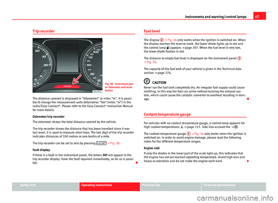
Fig. 38 Instrument pan-
el: Odometer and reset
button
The distance covered is displayed in “kilometres” or miles “m”. It is possi-
ble to change the measurement units (kilometres “km”/miles “m”) in the
radio/Easy Connect*. Please refer to the Easy Connect* Instruction Manual
for more details.
Odometer/trip recorder
The odometer shows the total distance covered by the vehicle.
The trip recorder shows the distance that has been travelled since it was
last reset. It is used to measure short trips. The last digit of the trip recorder
indicates distances of 100 metres or one tenths of a mile.
The trip recorder can be set to zero by pressing 0.0/SET
⇒ Fig. 38.
Fault display
If there is a fault in the instrument panel, the letters DEF will appear in the
trip recorder display. Have the fault repaired immediately, as far as is possi-
ble. Fuel level
The display
6 ⇒ Fig. 36 only works when the ignition is switched on. When
the display reaches the reserve mark, the lower diode lights up in red and
the control lamp appears ⇒ page 207. When the fuel level is very low,
the lower diode flashes in red.
The distance to empty fuel level is displayed on the instrument panel 3
⇒ Fig. 36.
The capacity of the fuel tank of your vehicle is given in the Technical data
section ⇒ page 276.
CAUTION
Never run the fuel tank completely dry. An irregular fuel supply could cause
misfiring. In this way the fuel can arrive without burning the exhaust sys-
tem, which could cause the catalytic converter to overheat resulting in dam-
age.
Coolant temperature gauge
For vehicles with no coolant temperature gauge, a control lamp appears for
high coolant temperatures ⇒ page 215. Take into account the ⇒ .
The coolant temperature gauge 2
⇒ Fig. 36 only works when the ignition is
switched on. In order to avoid engine damage, please read the following
notes for the different temperature ranges.
Engine cold
If only the diodes in the lower part of the scale light up, this indicates that
the engine has not yet reached operating temperature. Avoid high revs and
heavy acceleration and do not make the engine work hard.
Safety FirstOperating instructionsPractical TipsTechnical specifications
Page 69 of 289

68Instruments and warning/control lamps
Normal temperature
If in normal operations, the diodes light up until the central zone, it means
that the engine has reached operating temperature. At high outside temper-
atures and when making the engine work hard, the diodes may continue
lighting up and reach the upper zone. This is no cause for concern, provided
the control lamp does not light up on the instrument panel digital dis-
play.
Heat range
When the diodes light up in the upper area of the display and the control
lamp appears on the instrument panel display, the coolant temperature
is excessive ⇒ page 215.
CAUTION
● To ensure a long useful life for the engine, avoid high revs, driving at
high speed and making the engine work hard for approx. the first 15 mi-
nutes when the engine is cold. The phase until the engine is warm also de-
pends on the outside temperature. If necessary, use the engine oil tempera-
ture* as a guide ⇒ page 77
● Additional lights and other accessories in front of the air inlet reduce the
cooling effect of the coolant. At high outside temperatures and high engine
loads, there is a risk of the engine overheating.
● The front spoiler also ensures proper distribution of the cooling air when
the vehicle is moving. If the spoiler is damaged this can reduce the cooling
effect, which could cause the engine to overheat. Seek specialist assis-
tance. Gear-change indicator
This additional indicator function can help to save fuel.
Fig. 39 Instrument pan-
el: Gear-change indicator
(manual gearbox)
To familiarise yourself with the gear-change indicator, we recommend driv-
ing in the normal way to start with. A gear change will be recommended if
the gear you are in is not the most economical choice.
If no gear-change is recommended, you are already in the most economical
gear.
Vehicles with a manual gearbox
The following display symbols ⇒ Fig. 39 mean:
● Change to a higher gear: The suggested gear appears to the right of
the current gear when a higher gear is recommended.
● Change to a lower gear: The suggested gear appears to the left of the
current gear when a lower gear is recommended.
The gear recommendation may occasionally skip a gear (2nd 4th).