technical data Seat Leon 5D 2014 Owner's manual
[x] Cancel search | Manufacturer: SEAT, Model Year: 2014, Model line: Leon 5D, Model: Seat Leon 5D 2014Pages: 284, PDF Size: 5.85 MB
Page 2 of 284
SEAT S.A. is permanently concerned about continuous development of its t\
ypes and models. For this reason we ask you to under-
stand, that at any given time, changes regarding shape, equipment and te\
chnique may take place on the car delivered. For this reason
no right at all may derive based on the data, drawings and descriptions \
in this current handbook.
All texts, illustrations and standards in this handbook are based on the\
status of information at the time of printing. Except for error
or omission, the information included in the current handbook is valid a\
s of the date of closing print.
Re-printing, copying or translating, whether total or partial is not all\
owed unless SEAT allows it in written form.
SEAT reserves all rights in accordance with the “Copyright” Act.
All rights on changes are reserved.
❀This paper has been manufactured using bleached non-chlorine cellulose.
© SEAT S.A. - Reprint: 15.11.14
About this manual
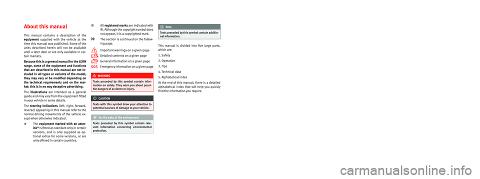
This manual contains a description of the
equipment supplied with the vehicle at the
time this manual was published. Some of the
units described herein will not be available
until a later date or are only available in cer -
tain markets.
Because this is a general manual for the LEON
range, some of the equipment and functions
that are described in this manual are not in-
cluded in all types or variants of the model;
they may vary or be modi�ed depending on
the technical requirements and on the mar -
ket; this is in no way deceptive advertising.
The illustrations are intended as a general
guide and may vary from the equipment �tted
in your vehicle in some details.
The steering indications (left, right, forward,
reverse) appearing in this manual refer to the
normal driving movements of the vehicle ex -
cept when otherwise indicated.
* The equipment marked with an aster -
isk* is �tted as standard only in certain
versions, and is only supplied as op -
tional extras for some versions, or are
only offered in certain countries. ®
All registered marks are indicated with
®. Although the copyright symbol does
not appear, it is a copyrighted mark.
>> The section is continued on the follow -
ing page.
Important warnings on a given page
Detailed contents on a given page
General information on a given page
Emergency information on a given page
WARNING
Texts preceded by this symbol contain infor -
mation on safety. They warn you about possi -
ble dangers of accident or injury.
CAUTION
Texts with this symbol draw your attention to
potential sources of damage to your vehicle.
For the sake of the environment
Texts preceded by this symbol contain rele-
vant information concerning environmental
protection.
Note
Texts preceded by this symbol contain additio -
nal information.
This manual is divided into �ve large parts,
which are:
1. Safety
2. Operation
3. Tips
4. Technical data
5. Alphabetical index
At the end of this manual, there is a detailed
alphabetical index that will help you quickly
�nd the information you require.
Page 6 of 284
Table of Contents
Compact temporary spare wheel . . . . . . . . . . . . 214
Winter service . . . . . . . . . . . . . . . . . . . . . . . . . . . 215
Emergencies . . . . . . . . . . . . . . . . . . . . . . . . . . . . 217
Changing a wheel . . . . . . . . . . . . . . . . . . . . . . . 217
Tyre repair . . . . . . . . . . . . . . . . . . . . . . . . . . . . . . 220
Jump starting . . . . . . . . . . . . . . . . . . . . . . . . . . . 223
Towing and tow-starting the vehicle . . . . . . . . . 224
Emergency locking and unlocking . . . . . . . . . . 227
Fuses and bulbs . . . . . . . . . . . . . . . . . . . . . . . . . 231
Fuses . . . . . . . . . . . . . . . . . . . . . . . . . . . . . . . . . . 231
Bulbs . . . . . . . . . . . . . . . . . . . . . . . . . . . . . . . . . . 233
Changing bulbs in headlight unit . . . . . . . . . . . 235
Changing bulb for front fog light* . . . . . . . . . . . 236
Changing tail light bulbs (on side panel) . . . . . 237
Changing tail light bulbs (on rear lid) . . . . . . . . 239
Technical specifications . . . . . . . . . . . . . . . 241
Technical specifications . . . . . . . . . . . . . . . . . . 241
Important . . . . . . . . . . . . . . . . . . . . . . . . . . . . . . 241
Vehicle identification data . . . . . . . . . . . . . . . . . 241
Information on fuel consumption . . . . . . . . . . . 242
Towing a trailer . . . . . . . . . . . . . . . . . . . . . . . . . . 243
Wheels . . . . . . . . . . . . . . . . . . . . . . . . . . . . . . . . 243
Engine specifications . . . . . . . . . . . . . . . . . . . . . 245
Dimensions . . . . . . . . . . . . . . . . . . . . . . . . . . . . . 267
Filling capacities . . . . . . . . . . . . . . . . . . . . . . . . 268
Index . . . . . . . . . . . . . . . . . . . . . . . . . . . . . . . . . 269
4
Page 21 of 284
The essentialsMenuSubmenuPossible settingDescription
Multifunction display–
Current consumption, average consumption, volume to fill up, convenience equipment,
ECOAdvice, journey duration, distance travelled, digital speed display, average speed,
speeding warning, oil temperature, coolant temperature, restore data “from start”, restore
data “total calculation”
›››
page 72
Date and time–Time source, set the time, automatic summer time setting, select time zone, time format, set
the date, date format–
Measurement units–Distance, speed, temperature, volume, consumption–
Service–Chassis number, date of next SEAT service inspection, date of next oil change service››› page 80
Factory settings–All settings can be reset: driver assistance, parking and manoeuvring, lights, rear view mir-
rors and windscreen wipers, opening and closing, multi-function display–
››› in Introduction on page 81
›››
page 81 Driver information system
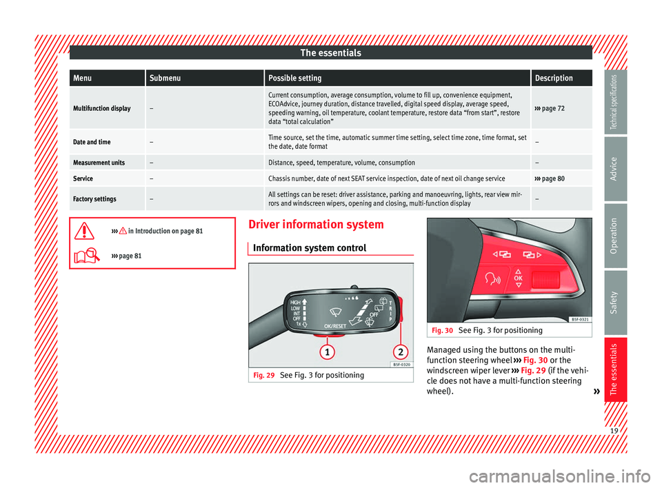
Information system control Fig. 29
See Fig. 3 for positioning Fig. 30
See Fig. 3 for positioning Managed using the buttons on the multi-
function steering wheel
››› Fig. 30 or the
w ind
screen wiper lever ››› Fig. 29 (if the vehi-
cle does not have a multi-function steering
wheel). » 19
Technical specifications
Advice
Operation
Safety
The essentials
Page 73 of 284

Instruments and warning/control lamps
The display 6
››› Fig. 82 only works when
the ignition i s
switched on. When the display
reaches the reserve mark, the lower diode
lights up in red and the control lamp
ap-
pears ››› page 66. When the fuel level is very
low
, the lower diode flashes in red.
The distance to empty fuel level is displayed
on the instrument panel 3
››› Fig. 82 .
The c ap
acity of the fuel tank of your vehicle is
given in the Technical data section
››› page 268. CAUTION
Never run the fuel tank completely dry. An ir-
regular fuel supply could cause misfiring. In
this way the unburned fuel can reach the ex-
haust system, which could cause the catalytic
converter to overheat resulting in damage. Control lamps
Control and warning lamps Read the additional information carefully
››› page 22
.
The c ontr
ol and warning lamps are indicators
of warnings, ››› , faults
››› or certain func-
tions. Some control and warning lamps come
on when the ignition is switched on, and
switch off when the engine starts running, or
while driving. Depending on the model, additional text
messages may be viewed on the instrument
panel display. These may be purely informa-
tive or they may be advising of the need for
action
››› page 66, Instruments .
D ependin
g upon the equipment fitted in the
vehicle, instead of a warning lamp, some-
times a symbol may be displayed on the in-
strument panel.
When certain control and warning lamps are
lit, an audible warning is also heard. WARNING
If the warning lamps and messages are ignor-
ed, the vehicle may stall in traffic, or may
cause accidents and severe injuries.
● Never ignore the warning lamps or text
messages.
● Stop the vehicle safely as soon as possible.
● Park the vehicle away from traffic and en-
sure that there are no highly flammable ma-
terials under the vehicle that could come into
contact with the exhaust system (e.g. dry
grass, fuel).
● A faulty vehicle represents a risk of acci-
dent for the driver and for other road users. If
necessary, switch on the hazard warning
lamps and put out the warning triangle to ad-
vise other drivers.
● Before opening the bonnet, switch off the
engine and allow it to cool. ●
In any vehicle, the engine compartment is a
hazardous area and could cause severe inju-
ries ››› page 198. CAUTION
Failure to heed the control lamps and text
messages when they appear may result in
faults in the vehicle. Engine management*
This warning lamp monitors the engine man-
agement system for petrol engines.
The warning lamp (Electronic Power Con-
trol) lights up when the ignition is switched
on while system operation is being verified. It
should go out once the engine is started.
If there is a fault in the electronic engine
management system while you are driving,
this warning lamp will light up. Stop the vehi-
cle and seek technical assistance.
Glow plug system/Engine fault* The warning lamp lights up to show that the
glow plugs are preheating the diesel engine.
The control lamp
lights up
If the control lamp lights up when the en-
gine is started it means that the glow plugs »
71Technical specifications
Advice
Operation
Safety
The essentials
Page 79 of 284

Driver information systemMenuFunction
Operating
range
a)
Approximate distance in km that can
still be travelled with the fuel remain-
ing in the tank, assuming the same
style of driving is maintained. This is
calculated using the current fuel con-
sumption.
Journey dura-
tionThis indicates the hours (h) and mi-
nutes (min) since the ignition was
switched on.
Distance cov-
eredDistance covered in km (m) after
switching on the ignition.
CNG quality
Whenever you refuel the quality of the
natural gas is automatically verified
and is displayed when the ignition is
switched on. The display is made in a
percentage of between 70% and
100%. The greater the percentage dis-
played the lower the consumption may
be.
Average speed
The average speed will be shown after
a distance of about 100 metres has
been travelled. Otherwise horizontal
lines are displayed. The value shown is
updated approximately every 5 sec-
onds.
Digital display
of speedCurrent speed displayed in digital for-
mat.
Speed warn-
ing at --- km/h
or Speed warning at ---
mphIf the stored speed is exceeded (be-
tween 30 - 250 km/h, or 19 -
155 mph), an audible warning is given
together with a visual warning.
MenuFunction
Oil tempera-
tureUpdated engine oil temperature digital
display
Coolant tem-
perature
gaugeDigital display of the current tempera-
ture of the liquid coolant.
a) In vehicles with a natural gas engine, range and average con-
sumption refer only to data or natural gas consumption. If you
are in “petrol mode”, the information of both data only appears
on the dash panel and not on the multifunction screen.
Storing a speed for the speed warning
● Select the display Speed warning at --- km/h
(--- mph)
● Press the button on the windscreen
wiper lever or the button on the multifunc-
tion steering wheel to store the current speed
and activate the warning.
● If necessary, adjust the desired speed with-
in 5 seconds using the rocker switch on
the windscreen wiper lever or by turning the
thumbwheel on the multifunction steering
wheel. Next, press the button or
again or wait several seconds. The speed is
stored and the warning activated.
● To deactivate it press the button
or
the button . The stored speed is deleted.Engine oil temperature display Vehicles without multifunction steering
wheel
– To view the temperature, press the rocker
button ››› Fig. 87 2 until the main menu
comes up. Enter into Journey data. With the
button 2 move to the oil temperature
gauge.
Vehicles with multifunction steering wheel
– To display the engine oil temperature, enter
the submenu Journey data and turn the
thumbwheel until the oil temperature dis-
play appears.
The engine reaches its operating temperature
when in normal driving conditions, the oil
temperature is between 80°C (180°F)
and
120°C (250°F) . If the engine is required to
work hard and the outside temperature is
high, the engine oil temperature can in-
crease. This does not present any problems
as long as the warning lamps ›››
ta-
ble on page 23 or ››
›
table on page 23
do not appear on the display.
Additional electrical appliances 3 Not available in vehicles equipped with natural
gas engine (CNG).
– Operation with the windscreen wiper lev-
er*: Press the rocker switch ›››
Fig. 87 2 »
77
Technical specifications
Advice
Operation
Safety
The essentials
Page 81 of 284

Driver information systemMenu “Pause”
Interr. lapThe timer of the current lap ends and is
cancelled. It is not included in the statis-
tics.
EndThe current timer ends. The lap is inclu-
ded in the statistics.
Menu “Partial time”
Partial timeFor about 5 seconds a partial time is dis-
played. The timer continues in parallel.
New lap
The timer of the current lap stops and a
new lap starts immediately. The time for
the lap you have just completed is inclu-
ded in the statistics.
StopThe current lap timer will be interrupted.
The lap does not end. The
Pause menu is
displayed.
Menu “Statistics”
View of the latest lap times:
– total time
– best lap time
– worst lap time
– average lap duration
A maximum of 10 laps is possible, and a
total duration of 99 hours, 59 minutes
and 59 seconds.
If one of the 2 limits is reached, you will
have to reset the statistics in order to be-
gin a new timer.
BackThis returns to the previous menu.
Menu “Statistics”
Resetting
to zeroAll the memorised statistical data are re-
set. WARNING
Do your best to avoid handling the timer
while driving.
● Only set the timer or consult statistics
when the vehicle is stationary.
● While driving, do not handle the timer in
complicated driving situations. Speed warning function
Introduction The speed warning function will warn the
driver if a pre-set maximum speed is excee-
ded. The system gives an warning buzzer sig-
nal if the set speed is exceeded by about 3
km/h. The warning lamp
and the driver
message Speed limit exceeded!
will be dis-
played simultaneously on the instrument
panel display. The warning lamp switches
off when reducing speed below the stored
maximum limit.
You are recommended to store this speed
limit warning if you always wish to be re-
minded of a particular speed limit. This could
be when driving in countries with general speed limits, or if a particular speed should
not be exceeded when winter tyres are fitted
etc.
Note
● Please bear in mind that, even with the
speed warning function, it is still important
to keep an eye on the vehicle speed with the
speedometer and to observe the legal speed
limits.
● The speed limit warning function in the ver-
sion for several countries warns you at a
speed of 120 km/h (80 mph). This is a facto-
ry-set speed limit. Setting speed limit warning
You can use the radio or the Easy Connect* to
set, alter or cancel the speed limit warning.
Vehicles with radio
–
Select: SETUP button > control button
Driver assistant > Speed warning
.
Vehicles with Easy Connect
– Select: Systems
control button or Vehicle
systems > Driver assistant
> Speed warning
.
The warning limit can be set from 30 to
240 km/h (20 to 150 mph). The adjustment
is done in 10 km/h (mph) intervals.
79
Technical specifications
Advice
Operation
Safety
The essentials
Page 85 of 284

Opening and closing
Note
● Never leave any valuable items in the vehi-
cle unattended. Even a locked vehicle is not a
safe.
● If the diode on the driver door sill lights up
for about 30 seconds when the vehicle is
locked, the central locking system or anti-
theft alarm* is not working properly. You
should have the fault repaired at a SEAT Offi-
cial Service or specialised workshop.
● The vehicle interior monitoring of the anti-
theft alarm* system will only function as in-
tended if the windows and the sunroof* are
closed. Car key
Fig. 91
Vehicle key Fig. 92
Vehicle key with alarm button Vehicle key
With the vehicle key the vehicle may be
locked or unlocked remotely
››› page 82.
The vehicle key includes an emitter and bat-
tery. The receiver is in the interior of the vehi-
cle. The range of the vehicle key with remote
control and new battery is several metres
around the vehicle.
If it is not possible to open or close the vehi-
cle using the remote control key, this should
be re-synchronised ››› page 87 or the bat-
tery changed ››› page 86 .
Diff er
ent keys belonging to the vehicle may
be used.
Control lamp on the vehicle key
When a button on the vehicle key is pressed,
the control lamp flashes ››› Fig. 91 (arrow)
once briefly
, but if the button is held down for a longer period the control lamp flashes sev-
eral times, such as in convenience opening.
If the vehicle key control lamp does not light
up when the button is pressed, replace the
key's battery
››› page 86.
Unfo
lding and folding the key shaft
Press button 1
››› Fig. 91 or
›
›› Fig. 92
to un-
lock and unfold the key shaft.
To fold the shaft away, press button 1 and
fold the key shaft in until it locks in place.
Alarm button*
Only press alarm button 2 in the event of an
emergency! When the alarm button is press-
ed, the vehicle horn is heard and the turn sig-
nals are switched on for a short time. When
the alarm button is pressed again, the alarm
is switched off.
Replacing a key
To obtain a spare key and other vehicle keys,
the vehicle chassis number is required.
Each new key contains a microchip which
must be coded with the data from the vehicle
electronic immobiliser. A vehicle key will not
work if it does not contain a microchip or the
microchip has not been encoded. This is also
true for keys which are specially cut for the
vehicle. »
83
Technical specifications
Advice
Operation
Safety
The essentials
Page 184 of 284
Advice
Advice
Care and maintenance
Accessories and modifications to the vehicle
Accessories, replacement parts and
repairs Always ask your dealer or specialist retailer
for advice before purchasing accessories and
replacement parts.
Your vehicle is designed to offer a high
standard of active and passive safety. For this
reason, we recommend that you ask a SEAT
Official Service for advice before fitting ac-
cessories or replacement parts. Your SEAT Of-
ficial Service has the latest information from
the manufacturer and can recommend acces-
sories and replacement parts which are suita-
ble for your requirements. They can also an-
swer any questions you might have regarding
official regulations.
We recommend you to use only
SEAT acces-
sories and
Genuine SEAT parts ®
. SEAT has
tested these parts and accessories for suita-
bility, reliability and safety. SEAT Official
Services have the necessary experience and
facilities to ensure that the parts are installed
correctly and professionally. Any
retro-fitted equipment which has a direct
effect on the vehicle and/or the way it is driv-
en, such as a cruise control system or elec-
tronically-controlled suspension, must be
approved for use in your vehicle and bear the
e mark (the European Union's authorisation
symbol).
If
any additional electrical devices are fitted
which do not serve to control the vehicle it-
self (for instance a refrigerator box, laptop or
ventilator fan, etc.), they must bear the
sign (manufacturer conformity declaration in
the European Union). WARNING
Accessories, for example telephone holders
or cup holders, should never be fitted on the
covers, or within the working range of the air-
bags. Otherwise, there is a danger of injury if
the airbag is triggered in an accident. Technical modifications
Modifications must always be carried out ac-
cording to our specifications.
Unauthorised modifications to the electronic
components, software, wiring or data transfer
in the vehicle may cause malfunctioning. Due
to the way the electronic components are
linked together in networks, other indirect
systems may be affected by the faults. This
can seriously impair safety, lead to excessivewear of components, and also invalidate your
vehicle registration documents.
You will appreciate that your SEAT dealership
cannot be held liable for any damage caused
by modifications and/or work performed in-
correctly.
We therefore recommend that all work should
be performed by a SEAT Official Service using
genuine SEAT parts
®
. WARNING
Incorrectly performed modifications or other
work on your vehicle can lead to malfunctions
and cause accidents. Two-way radios and office equipment
Radio transmitters (fixed installation)
Any retrofit installations of radio transmitters
in the vehicle require prior approval. SEAT
generally authorises in-vehicle installations
of approved types of radio transmitters provi-
ded that:
●
The aerial is installed correctly.
● The aerial is installed on the exterior of the
vehicle (and shielded cables are used togeth-
er with non-reflective aerial trimming).
● The effective transmitting power does not
exceed 10 Watts at the aerial base.
182
Page 243 of 284

Technical specifications
Technical specifications
Technical specifications Important The information in the vehicle documentation
always takes precedence over the informa-
tion in this Instruction Manual.
All technical specifications provided in this
documentation are valid for the standard
model in Spain. The vehicle data card inclu-
ded in the Maintenance Programme or the
vehicle registration documents shows which
engine is installed in the vehicle.
The figures may be different depending
whether additional equipment is fitted, for
different models, for special vehicles and for
other countries.
Abbreviations used in the Technical
Specifications sectionAb-
brevia- tionMeaning
kWKilowatt, engine power measurement.
PSPferdestärke (horsepower), formerly used to
denote engine power.
rpmRevolutions per minute - engine speed.
NmNewton metres, unit of engine torque.
litresper
100 kmFuel consumption in litres per 100 km (70
miles).
g/kmCarbon dioxide emissions in grams per km
(mile) travelled.
CO 2Carbon dioxide
CNCetane number, indication of the diesel com-
bustion power.
RONResearch octane number, indication of the
knock resistance of petrol. Vehicle identification data
Fig. 225
Vehicle data sticker (boot). Fig. 226
Chassis number.
» 241
Technical specifications
Advice
Operation
Safety
The essentials
Page 244 of 284
Technical specifications
VIN in the Easy Connect – Select: Function button CAR > control but-
ton (Car)* Systems > Service & Control >
Ch a
ssis number .
Chassis number
The VIN is located in the Easy Connect, on the
vehicle data sticker and under the wind-
screen, on the driver side ››› Fig. 226. Addi-
tional
ly, the chassis number is located in the
engine compartment, on the right-hand side.
The number is engraved on the top side rail,
and is partially covered.
Type plate
The type plate is located on the right side
door pillar. Vehicles for certain export coun-
tries do not have a type plate.
Vehicle data sticker
The vehicle data sticker is under the carpet
trim in the luggage compartment, in the
spare wheel well. A sticker with the vehicle
data is attached to the inside cover of the
Maintenance Programme.
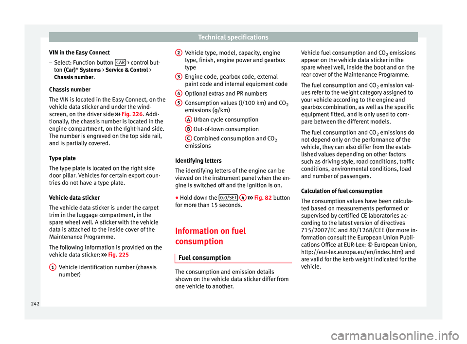
The following information is provided on the
vehicle data sticker: ››› Fig. 225
Vehicle identification number (chassis
number)
1 Vehicle type, model, capacity, engine
type, finish, engine power and gearbox
type
Engine code, gearbox code, external
paint code and internal equipment code
Optional extras and PR numbers
Consumption values (l/100 km) and CO
2
emissions (g/km)
A Urban cycle consumption
B Out-of-town consumption
C Combined consumption and CO
2
emissions
Identifying letters
The identifying letters of the engine can be
viewed on the instrument panel when the en-
gine is switched off and the ignition is on.
● Hold down the 0.0/SET
4
››› Fig. 82 button
for more than 15 seconds.
Information on fuel
consumption
Fuel consumption The consumption and emission details
shown on the vehicle data sticker differ from
one vehicle to another.2 3
4
5 Vehicle fuel consumption and CO
2 emissions
appear on the vehicle data sticker in the
spare wheel well, inside the boot and on the
rear cover of the Maintenance Programme.
The fuel consumption and CO 2 emission val-
ues refer to the weight category assigned to
your vehicle according to the engine and
gearbox combination, as well as the specific
equipment fitted, and is only used to com-
pare between the different models.
The fuel consumption and CO 2 emissions do
not depend only on the performance of the
vehicle, they can also differ from the estab-
lished values depending on other factors
such as driving style, road conditions, traffic
conditions, environmental conditions, load
and number of passengers.
Calculation of fuel consumption
The consumption values have been calcula-
ted based on measurements performed or
supervised by certified CE laboratories ac-
cording to the latest version of directives
715/2007/EC and 80/1268/CEE (for more in-
formation consult the European Union Publi-
cations Office at EUR-Lex: © European Union,
http://eur-lex.europa.eu/en/index.htm) and
are valid for the kerb weight indicated for the
vehicle.
242