ignition Seat Leon 5D 2015 User Guide
[x] Cancel search | Manufacturer: SEAT, Model Year: 2015, Model line: Leon 5D, Model: Seat Leon 5D 2015Pages: 308, PDF Size: 5.93 MB
Page 38 of 308
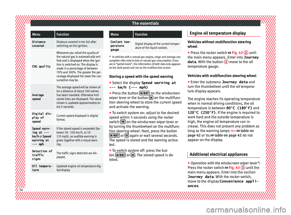
The essentialsMenuFunction
Distance
coveredDistance covered in km (m) after
switching on the ignition.
CNG quality
Whenever you refuel the quality of
the natural gas is automatically veri-
fied and is displayed when the igni-
tion is switched on. The display is
made in a percentage of between
70% and 100%. The greater the per-
centage displayed the lower the con-
sumption may be.
Average
speed
The average speed will be shown af-
ter a distance of about 100 metres
has been travelled. Otherwise hori-
zontal lines are displayed. The value
shown is updated approximately ev-
ery 5 seconds.
Digital dis- play of
speedCurrent speed displayed in digital
format.
Speed warn-
ing at ---
km/h or Speed
warning at
--- mphIf the stored speed is exceeded (be-
tween 30 - 250 km/h, or 19 -
155 mph), an audible warning is
given together with a visual warn-
ing.
Detection of
traffic
signsThe traffic signs detected are dis-
played.
Oil tempera- tureUpdated engine oil temperature dig-
ital display
MenuFunction
Coolant tem-perature
gaugeDigital display of the current temper-
ature of the liquid coolant.
a) In vehicles with a natural gas engine, range and average con-
sumption refer only to data or natural gas consumption. If you
are in “petrol mode”, the information of both data only appears
on the dash panel and not on the multifunction screen.
Storing a speed with the speed warning
● Select the display Speed warning at
--- km/h (---
mph)
● Press the button
on the windscreen
w iper l
ev
er or the button on the multifunc-
tion s t
eerin
g wheel to store the current speed
and activate the warning.
● To switch system on: adjust to the desired
speed within 5 sec
onds using the rocker
switch on the windscreen wiper lever or
b y
t
urning the thumbwheel on the multifunc-
tion steering wheel. Next, press the button or
again or wait several seconds.
The s peed i
s
stored and the warning activa-
ted.
● To switch system off: press the but-
ton or
. The stored speed is de-
l et
ed. En
gine oil temperature display Vehicles without multifunction steering
wheel
● Press the rocker switch ›››
Fig. 43 2 until
the main menu ap pe
ars. Enter into Journey
data . With the button 2 move to the oil
temper at
ure gauge.
Vehicles with multifunction steering wheel
● Enter the submenu Journey data and
turn the thumbwheel
until the oil tempera-
ture display appears.
The engine reaches its operating temperature
when in normal driving conditions, the oil
temperature is between 80°C (180°F) and
120°C (250°F) . If the engine is required to
work hard and the outside temperature is
high, the engine oil temperature can in-
crease. This does not present any problem as
long as the warning lamps ›››
table on
page 42 or ›››
table on page 42 do not
appear on the display.
Additional electrical appliances ●
Operation with the windscreen wiper lever*:
Pr e
s
s the rocker switch ›››
Fig. 43 2 until the
m ain menu ap
pe
ars. Enter into the section
Journey data . With the rocker switch,
move to the display Convenience appli-
ances .36
Page 39 of 308
The essentials
● Oper ation with
the
multi-function steering
wheel*: Move with the buttons 1 or
2 to
Journey data and enter w
ith
OK . Turn the
thumbwheel to the right until the Conven-
ience appliances display appears.
In addition, a scale will inform you of the cur-
rent sum of all the additional appliances.
Saving tips Tips on how to save fuel will be displayed in
c
ondition
s
that increase fuel consumption.
Follow them to reduce consumption. The indi-
cations appear automatically only with the ef-
ficiency programme. After a time, the tips will
disappear automatically.
If you wish to hide a saving tip immediately
after it appears, press any button on the
windscreen wiper lever*/multifunction steer-
ing wheel*. Note
● If y
ou hide a saving tip, it will reappear af-
ter you switch the ignition on again.
● The saving tips do not appear in all situa-
tions, but
rather with a large separation of
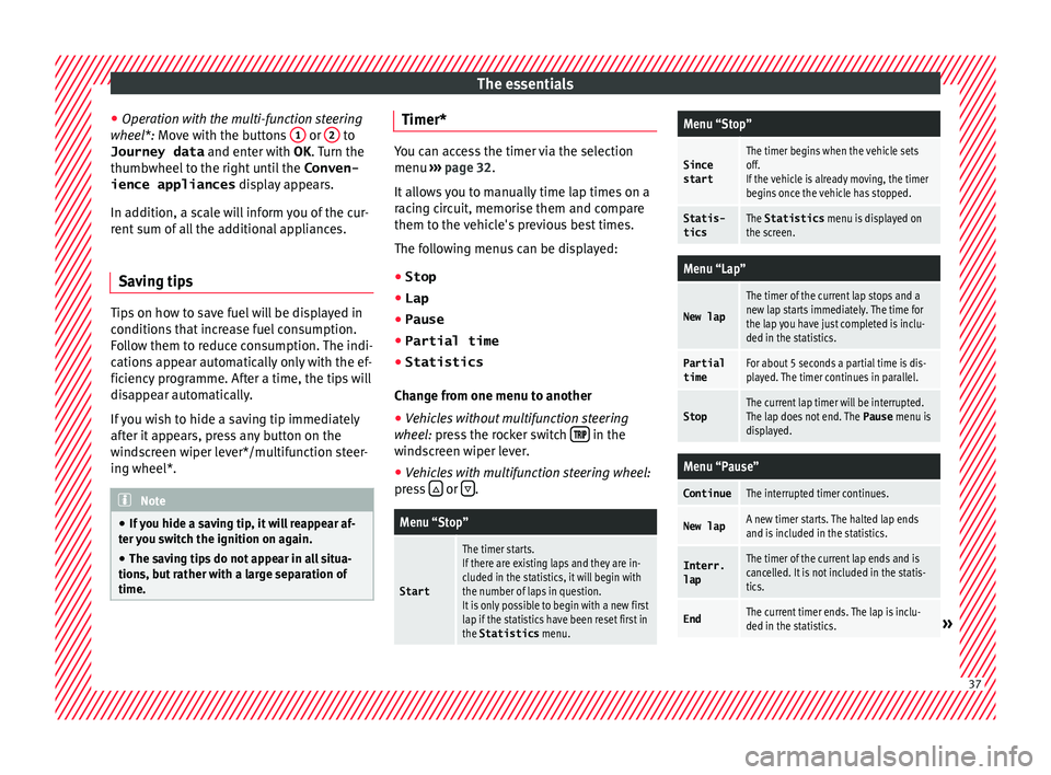
time. Timer*
You can access the timer via the selection
menu
›››
page 32.
It allows you to manually time lap times on a
racing circuit, memorise them and compare
them to the vehicle's previous best times.
The following menus can be displayed:
● Stop
● Lap
● Pause
● Partial time
● Statistics
Chang
e from one menu to another
● Vehicles without multifunction steering
whee l:
press the rocker switch in the
w ind
s
creen wiper lever.
● Vehicles with multifunction steering wheel:
pres
s or
.
Menu “Stop”
Start
The timer starts.
If there are existing laps and they are in-
cluded in the statistics, it will begin with
the number of laps in question.
It is only possible to begin with a new first
lap if the statistics have been reset first in
the Statistics
menu.
Menu “Stop”
Since
startThe timer begins when the vehicle sets
off.
If the vehicle is already moving, the timer
begins once the vehicle has stopped.
Statis-
ticsThe Statistics menu is displayed on
the screen.
Menu “Lap”
New lap
The timer of the current lap stops and a
new lap starts immediately. The time for
the lap you have just completed is inclu-
ded in the statistics.
Partial timeFor about 5 seconds a partial time is dis-
played. The timer continues in parallel.
StopThe current lap timer will be interrupted.
The lap does not end. The Pause menu is
displayed.
Menu “Pause”
ContinueThe interrupted timer continues.
New lapA new timer starts. The halted lap ends
and is included in the statistics.
Interr. lapThe timer of the current lap ends and is
cancelled. It is not included in the statis-
tics.
EndThe current timer ends. The lap is inclu-
ded in the statistics.» 37
Page 41 of 308
The essentials
you only need to change the oil when the ve-
hic l
e so r
equires. To calculate this change
(max. 2 years), the vehicle's conditions of
use and individual driving styles are consid-
ered. The pre-warning first appears 20 days
before the date established for the corre-
sponding service. The kilometres (miles) re-
maining until the next service are always
rounded up to the nearest 100 km (miles)
and the time is given in complete days. The
current service message cannot be viewed
until 500 km after the last service. Prior to
this, only lines are visible on the display.
Inspection reminder
When the Service date is approaching, when
the ignition is switched on a Service remind-
er is displayed.
Vehicles without text messages : a span-
ner will be displayed on the instrument
panel plus an indication in km.
The kilometres indicated are the maximum
number of kilometres that can be travelled
until the next service. After a few seconds,
the display mode changes. A clock symbol
appears and the number of days until the
next service is due.
Vehicles with text messages : Service in
--- km or --- days will be shown on the
instrument panel display. Service due
When the servic
e date is due, an audible
warning is given when the ignition is switch-
ed on and the spanner displayed on the
screen flashes for a few seconds .
Vehicles with text messages : Service now
will be shown on the instrument panel dis-
play.
Reading a service notification
With the ignition switched on, the engine off
and the vehicle at a standstill, the current
service notification can be read:
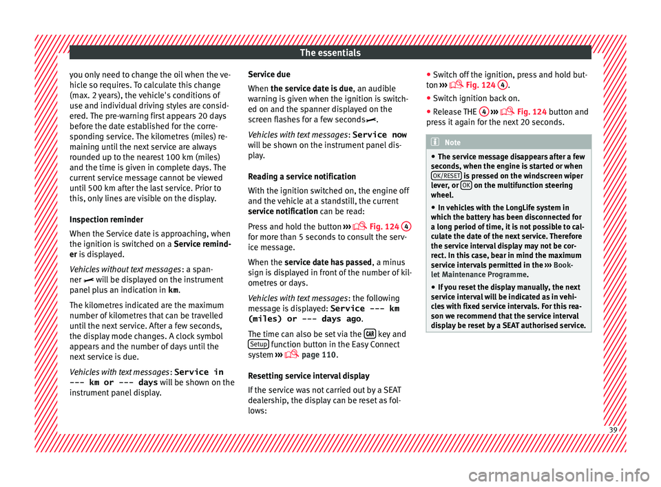
Press and hold the button ›››
Fig. 124
4 for more than 5 seconds to consult the serv-
ic
e me
s
sage.
When the service date has passed , a minus
sign is displayed in front of the number of kil-
ometres or days.
Vehicles with text messages : the following
message is displayed: Service --- km
(miles) or --- days ago .
The time can also be set via the key and
Set up function button in the Easy Connect
sy s
t
em ›››
page 110.
Resetting service interval display
If the service was not carried out by a SEAT
dealership, the display can be reset as fol-
lows: ●
Switc
h off the ignition, press and hold but-
ton ›››
Fig. 124
4 .
● Switch ignition back on.
● Release THE 4
› ››
Fig. 124
b
utton and
press it again for the next 20 seconds. Note
● The serv ic
e message disappears after a few
seconds, when the engine is started or when OK/RESET is pressed on the windscreen wiper
lev er
, or OK on the multifunction steering
wheel.
● In v
ehicles with the LongLife system in
which the batt
ery has been disconnected for
a long period of time, it is not possible to cal-
culate the date of the next service. Therefore
the service interval display may not be cor- rect. In this case, bear in mind the maximum
service intervals permitted in the ››› Book-
let Maintenance Programme.
● If you reset the display manually, the next
servic
e interval will be indicated as in vehi-
cles with fixed service intervals. For this rea-
son we recommend that the service interval
display be reset by a SEAT authorised service. 39
Page 44 of 308
The essentials
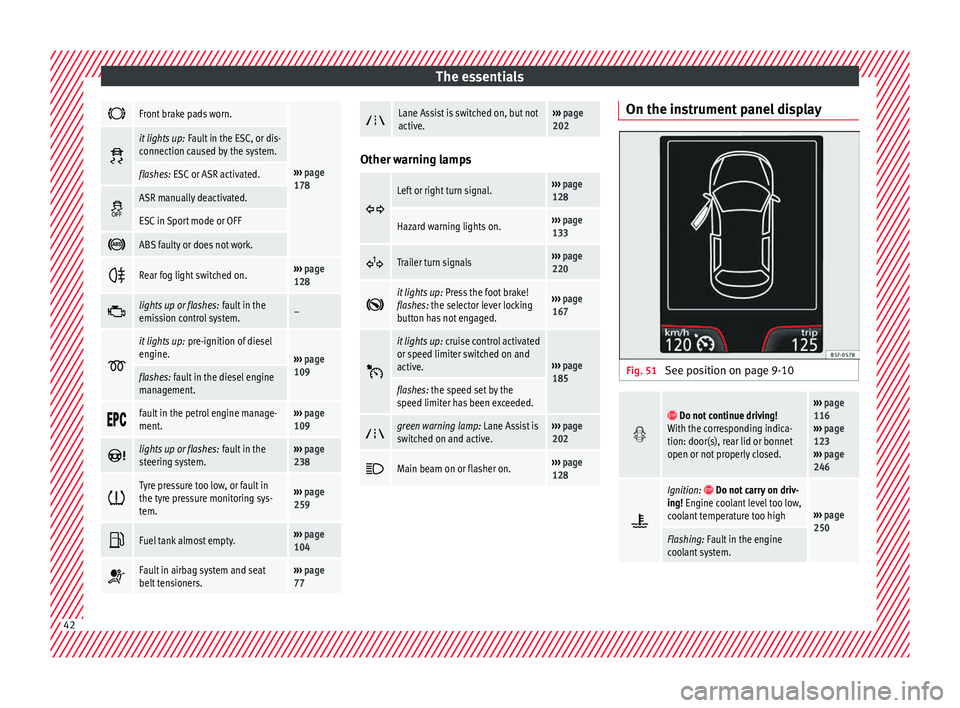
Front brake pads worn.
›››
page
178
it lights up:
Fault in the ESC, or dis-
connection caused by the system.
flashes: ESC or ASR activated.
ASR manually deactivated.
ESC in Sport mode or OFF
ABS faulty or does not work.
Rear fog light switched on.›››
page
128
lights up or flashes:
fault in the
emission control system.–
it lights up:
pre-ignition of diesel
engine.
››› page
109
flashes: fault in the diesel engine
management.
fault in the petrol engine manage-
ment.›››
page
109
lights up or flashes:
fault in the
steering system.››› page
238
Tyre pressure too low, or fault in
the tyre pressure monitoring sys-
tem.›››
page
259
Fuel tank almost empty.›››
page
104
Fault in airbag system and seat
belt tensioners.›››
page
77
Lane Assist is switched on, but not
active.›››
page
202 Other warning lamps
Left or right turn signal.›››
page
128
Hazard warning lights on.››› page
133
Trailer turn signals›››
page
220
it lights up:
Press the foot brake!
flashes: the selector lever locking
button has not engaged.››› page
167
it lights up:
cruise control activated
or speed limiter switched on and
active.
››› page
185
flashes: the speed set by the
speed limiter has been exceeded.
green warning lamp: Lane Assist is
switched on and active.›››
page
202
Main beam on or flasher on.›››
page
128 On the instrument panel display
Fig. 51
See position on page 9-10
Do not continue driving!
With the corresponding indica-
tion: door(s), rear lid or bonnet
open or not properly closed.››› page
116
››› page
123
››› page
246
Ignition: Do not carry on driv-
ing! Engine coolant level too low,
coolant temperature too high
››› page
250
Flashing: Fault in the engine
coolant system. 42
Page 45 of 308
The essentials
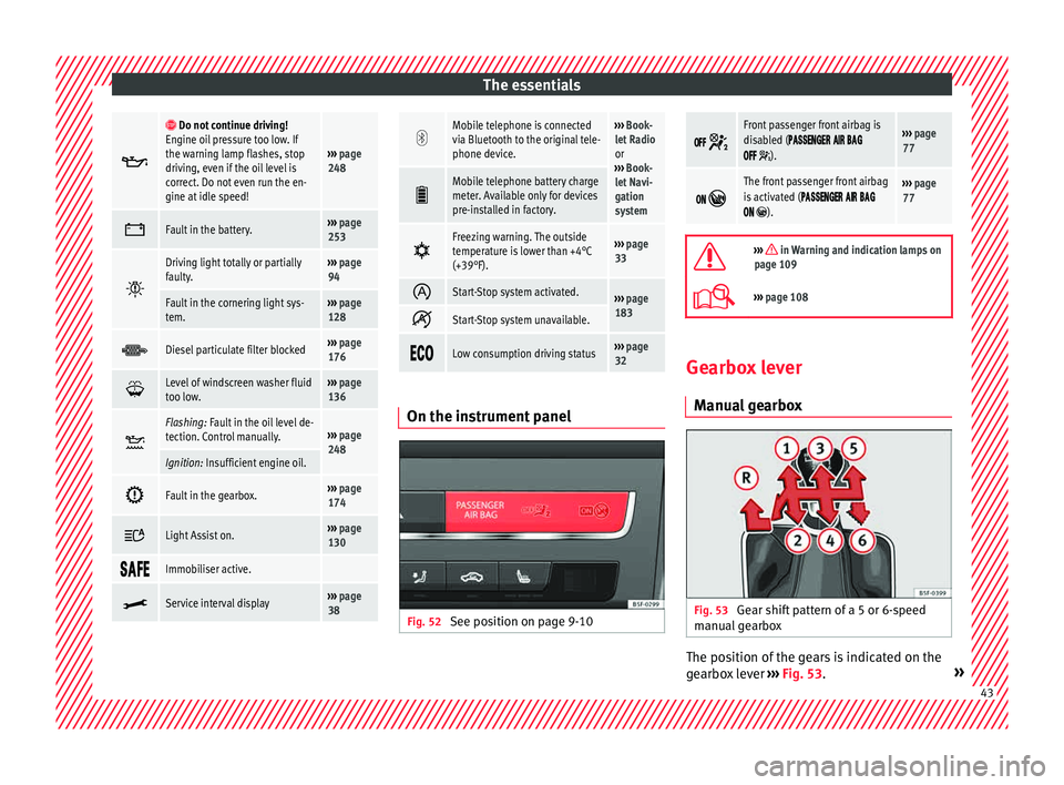
Do not continue driving!
Engine oil pressure too low. If
the warning lamp flashes, stop
driving, even if the oil level is
correct. Do not even run the en-
gine at idle speed!
››› page
248
Fault in the battery.›››
page
253
Driving light totally or partially
faulty.›››
page
94
Fault in the cornering light sys-
tem.››› page
128
Diesel particulate filter blocked›››
page
176
Level of windscreen washer fluid
too low.›››
page
136
Flashing: Fault in the oil level de-
tection. Control manually.›››
page
248
Ignition: Insufficient engine oil.
Fault in the gearbox.›››
page
174
Light Assist on.›››
page
130
Immobiliser active.
Service interval display›››
page
38
Mobile telephone is connected
via Bluetooth to the original tele-
phone device.›››
Book-
let Radio
or
››› Book-
let Navi-
gation
system
Mobile telephone battery charge
meter. Available only for devices
pre-installed in factory.
Freezing warning. The outside
temperature is lower than +4°C
(+39°F).›››
page
33
Start-Stop system activated.›››
page
183
Start-Stop system unavailable.
Low consumption driving status›››
page
32 On the instrument panel
Fig. 52
See position on page 9-10
Front passenger front airbag is
disabled (
).
››› page
77
The front passenger front airbag
is activated (
).
››› page
77
››› in Warning and indication lamps on
page 109
››› page 108 Gearbox lever
M anua
l
gearbox Fig. 53
Gear shift pattern of a 5 or 6-speed
m anual
g
earbox The position of the gears is indicated on the
g
e
arbo
x lever ››› Fig. 53. » 43
Page 57 of 308
The essentials
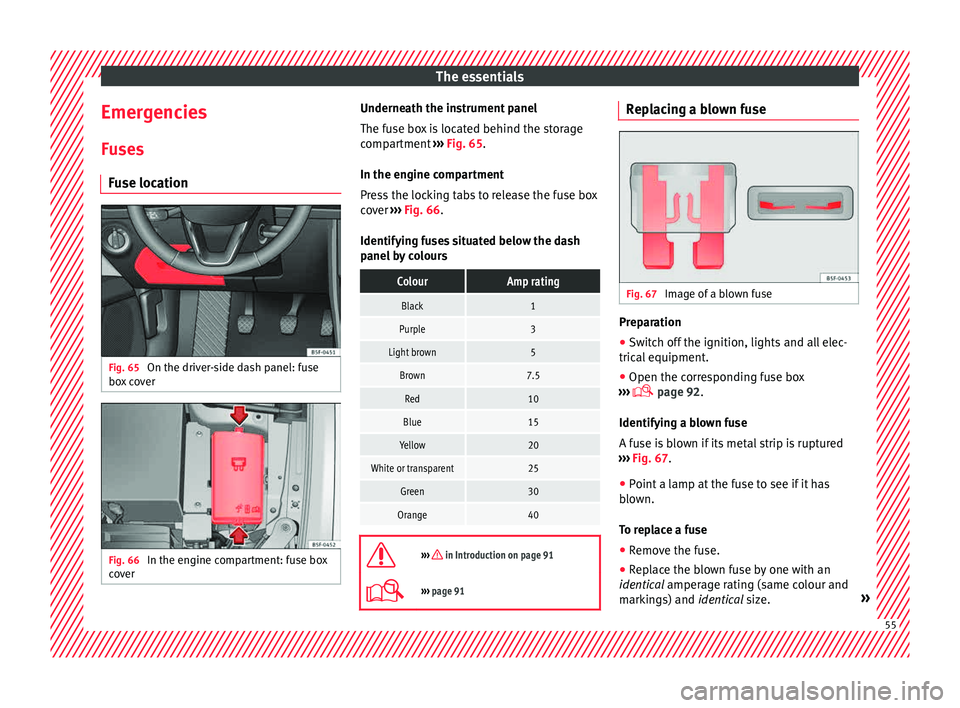
Emergencies F u
se
s
Fuse location Fig. 65
On the driver-side dash panel: fuse
bo x
c
over Fig. 66
In the engine compartment: fuse box
c o
v
er Underneath the instrument panel
The f
use bo
x is located behind the storage
compartment ››› Fig. 65.
In the engine compartment
Press the locking tabs to release the fuse box
cover ››› Fig. 66.
Identifying fuses situated below the dash
panel by colours
ColourAmp rating
Black1
Purple3
Light brown5
Brown7.5
Red10
Blue15
Yellow20
White or transparent25
Green30
Orange40
››› in Introduction on page 91
›››
page 91 Replacing a blown fuse
Fig. 67
Image of a blown fuse Preparation
● Switch off the ignition, lights and all elec-
tric al
equipment
.
● Open the corresponding fuse box
›››
page 92.
Identifying a blown fuse
A fuse is blown if its metal strip is ruptured
››› Fig. 67.
● Point a lamp at the fuse to see if it has
blown.
T
o replace a fuse
● Remove the fuse.
● Replace the blown fuse by one with an
identica
l amperage rating (same colour and
markings) and identical size. » 55
Page 64 of 308
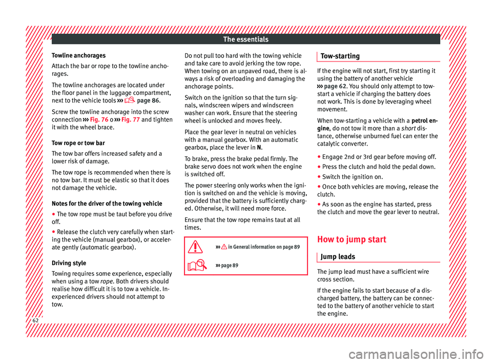
The essentials
Towline anchorages
Att ac
h the b
ar or rope to the towline ancho-
rages.
The towline anchorages are located under
the floor panel in the luggage compartment,
next to the vehicle tools ›››
page 86.
Screw the towline anchorage into the screw
connection ››› Fig. 76 o ››› Fig. 77 and tighten
it with the wheel brace.
Tow rope or tow bar
The tow bar offers increased safety and a
lower risk of damage.
The tow rope is recommended when there is
no tow bar. It must be elastic so that it does
not damage the vehicle.
Notes for the driver of the towing vehicle
● The tow rope must be taut before you drive
off.
● Rel
ease the clutch very carefully when start-
ing the v
ehicle (manual gearbox), or acceler-
ate gently (automatic gearbox).
Driving style
Towing requires some experience, especially
when using a tow rope. Both drivers should
realise how difficult it is to tow a vehicle. In-
experienced drivers should not attempt to
tow. Do not pull too hard with the towing vehicle
and take c
are to avoid jerking the tow rope.
When towing on an unpaved road, there is al-
ways a risk of overloading and damaging the
anchorage points.
Switch on the ignition so that the turn sig-
nals, windscreen wipers and windscreen
washer can work. Ensure that the steering
wheel is unlocked and moves freely.
Place the gear lever in neutral on vehicles
with a manual gearbox. With an automatic
gearbox, place the lever in N.
To brake, press the brake pedal firmly. The
brake servo does not work when the engine
is switched off.
The power steering only works when the igni-
tion is switched on and the vehicle is moving,
provided that the battery is sufficiently charg-
ed. Otherwise, it will need more force.
Ensure that the tow rope remains taut at all
times.
››› in General information on page 89
››› page 89 Tow-starting
If the engine will not start, first try starting it
us
in
g the battery of another vehicle
››› page 62. You should only attempt to tow-
start a vehicle if charging the battery does
not work. This is done by leveraging wheel
movement.
When tow-starting a vehicle with a petrol en-
gine, do not tow it more than a short dis-
tance, otherwise unburned fuel can enter the
catalytic converter.
● Engage 2nd or 3rd gear before moving off.
● Press the clutch and hold the pedal down.
● Switch the ignition on.
● Once both vehicles are moving, release the
clut c
h.
● As soon as the engine has started, press
the clutc
h and move the gear lever to neutral.
How to jump start Jump lea
ds The jump lead must have a sufficient wire
c
r
o
ss section.
If the engine fails to start because of a dis-
charged battery, the battery can be connec-
ted to the battery of another vehicle to start
the engine. 62
Page 65 of 308

The essentials
Jump leads must comply with standard DIN
72553 (see c ab
l
e manufacturer's instruc-
tions). The wire cross section must be at least
25 mm 2
for petrol engines and at least
35 mm 2
for diesel engines. Note
● The v ehic
les must not touch each other,
otherwise electricity could flow as soon as
the positive terminals are connected.
● The discharged battery must be properly
connected t
o the on-board network. How to jump start: description
Fig. 78
Diagram of connections for vehicles
w ithout
Start Stop system Fig. 79
Diagram of connections for vehicles
with St
art Stop system Jump lead terminal connections
1. Switch off the ignition of both vehicles
››
›
.
2. Connect one end of the re
d
jump lead to
the positive + terminal of the vehicle
w ith the fl
at
battery A
› ›
› Fig. 78 .
3. Connect the other end of the red
jump
lead to the positive terminal + in the ve-
hic l
e pr
oviding assistance B .
4. For vehicles without Start-Stop system:
connect
one end of
the black jump lead to
the negative terminal – of the vehicle
pr o
v
iding the current B
› ›
› Fig. 78 .
– For vehicles with Start-Stop system: con-
nect one end of
the black jump lead X to a
s uit
ab
le ground terminal, to a solid piece of
metal in the engine block, or to the engine
block itself ››› Fig. 79. 5. Connect the other end of the
black
jump
lead X to a solid metal component bolted
t o the en
gine b
lock or to the engine block
itself of the vehicle with the flat battery.
Do not connect it to a point near the bat-
tery A .
6. Position the leads in such a way that they cannot
c
ome into contact with any moving
parts in the engine compartment.
Starting
7. Start the engine of the vehicle with the boostin
g battery and let it run at idling
speed.
8. Start the engine of the vehicle with the flat batter
y and wait for 2 or 3 minutes until
the engine is running.
Removing the jump leads
9. Before you remove the jump leads, switch off the dipped be
am headlights if they are
switched on.
10.
Turn on the heater blower and heated rear
window in the vehicle with the flat battery.
This helps minimise voltage peaks which
are generated when the leads are discon-
nected.
11.When the engine is running, disconnect the lea
ds in reverse order to the details
given above. » 63
Page 66 of 308
The essentials
Make sure the battery clamps have sufficient
met al-t
o-met
al contact with the battery termi-
nals.
If the engine fails to start after about 10 sec-
onds, switch off the starter and try again after
about 1 minute. WARNING
● Ple a
se note the safety warnings referring to
working in the engine compartment
››› page 246.
● The battery providing assistance must have
the same v
oltage as the flat battery (12V) and
approximately the same capacity (see imprint
on battery). Failure to comply could result in
an explosion.
● Never use jump leads when one of the bat-
teries
is frozen. Danger of explosion! Even af-
ter the battery has thawed, battery acid could
leak and cause chemical burns. If a battery
freezes, it should be replaced.
● Keep sparks, flames and lighted cigarettes
awa
y from batteries, danger of explosion.
Failure to comply could result in an explo-
sion.
● Observe the instructions provided by the
manufact
urer of the jump leads.
● Do not connect the negative cable from the
other vehic
le directly to the negative terminal
of the flat battery. The gas emitted from the
battery could be ignited by sparks. Danger of
explosion. ●
Do not att ac
h the negative cable from the
other vehicle to parts of the fuel system or to
the brake line.
● The non-insulated parts of the battery
clamp
s must not be allowed to touch. The
jump lead attached to the positive battery
terminal must not touch metal parts of the ve-
hicle, this can cause a short circuit.
● Position the leads in such a way that they
cannot c
ome into contact with any moving
parts in the engine compartment.
● Do not lean on the batteries. This could re-
sult
in chemical burns. Note
The vehicles must not touch each other, oth-
erw i
se electricity could flow as soon as the
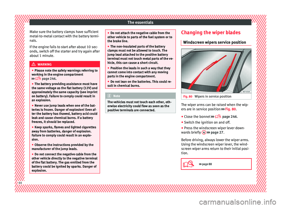
positive terminals are connected. Changing the wiper blades
W ind
s
creen wipers service position Fig. 80
Wipers in service position The wiper arms can be raised when the wip-
er
s
ar
e in service position ››› Fig. 80.
● Close the bonnet ›››
page 246.
● Switch the ignition on and off.
● Press the windscreen wiper lever down-
ward
s briefly 4
› ›
› page 27.
Before driving, always lower the wiper arms.
Using the windscreen wiper lever, the wind-
screen wiper arms return to their initial posi-
tion.
››› page 88 64
Page 74 of 308
Safety
Seat belts
Wh y
w
ear a seat belt?
Number of seats Your vehicle has
five se
ats, two in the front
and three in the rear. Each seat is equipped
with a three-point seat belt.
In some versions, your vehicle is approved
only for four seats. Two front seats and two
rear seats. WARNING
● Never tr an
sport more than the permitted
amount of people in your vehicle.
● Every vehicle occupant must properly fas-
ten and we
ar the seat belt belonging to his or
her seat. Children must be protected with an
appropriate child restraint system. Seat belt lamp*
Fig. 88
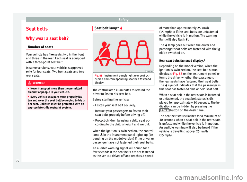
Instrument panel: right rear seat oc-
c upied and c
orr
esponding seat belt fastened
display. The control lamp illuminates to remind the
driv
er t
o f
asten his seat belt.
Before starting the vehicle: – Fasten your seat belt securely.
– Instruct your passengers to fasten their
seat belts
properly before driving off.
– Protect children by using a child seat ac-
cordin
g to the child's height and weight.
When the ignition is switched on, the control
lamp in the instrument panel lights up (de-
pending on the model version) if the driver or
passenger have not fastened their seat belts.
An audible warning signal will sound for a
few seconds if the seat belts are not fastened
as the vehicle drives off and reaches a speed of more than approximately 25 km/h
(15 mph) or if the seat
belts are unfastened
while the vehicle is in motion. The warning
light will also flash .
The lamp goes out when the driver and
passenger seat belts are fastened with the ig-
nition switched on.
Rear seat belts fastened display.*
Depending on the model version, when the
ignition is switched on, the seat belt status
display ››› Fig. 88 on the instrument panel in-
forms the driver whether the passengers in
the rear seats have fastened their seat belts.
The symbol indicates that the passenger in
this seat has fastened “his or her” seat belt.
When a seat belt in the rear seats is fastened
or unfastened, the seat belt status is dis-
played for approximately 30 seconds. The in-
dication can be hidden by pressing the 0.0/SET button on the dash panel.
The se at
belt
status flashes for a maximum of
30 seconds when a seat belt in the rear seats
is unfastened while the vehicle is in motion.
An audible warning will also be heard if the
vehicle is travelling at over 25 km/h
(15 mph).
72