lock Seat Leon 5D 2015 User Guide
[x] Cancel search | Manufacturer: SEAT, Model Year: 2015, Model line: Leon 5D, Model: Seat Leon 5D 2015Pages: 308, PDF Size: 5.93 MB
Page 44 of 308
The essentials
Front brake pads worn.
›››
page
178
it lights up:
Fault in the ESC, or dis-
connection caused by the system.
flashes: ESC or ASR activated.
ASR manually deactivated.
ESC in Sport mode or OFF
ABS faulty or does not work.
Rear fog light switched on.›››
page
128
lights up or flashes:
fault in the
emission control system.–
it lights up:
pre-ignition of diesel
engine.
››› page
109
flashes: fault in the diesel engine
management.
fault in the petrol engine manage-
ment.›››
page
109
lights up or flashes:
fault in the
steering system.››› page
238
Tyre pressure too low, or fault in
the tyre pressure monitoring sys-
tem.›››
page
259
Fuel tank almost empty.›››
page
104
Fault in airbag system and seat
belt tensioners.›››
page
77
Lane Assist is switched on, but not
active.›››
page
202 Other warning lamps
Left or right turn signal.›››
page
128
Hazard warning lights on.››› page
133
Trailer turn signals›››
page
220
it lights up:
Press the foot brake!
flashes: the selector lever locking
button has not engaged.››› page
167
it lights up:
cruise control activated
or speed limiter switched on and
active.
››› page
185
flashes: the speed set by the
speed limiter has been exceeded.
green warning lamp: Lane Assist is
switched on and active.›››
page
202
Main beam on or flasher on.›››
page
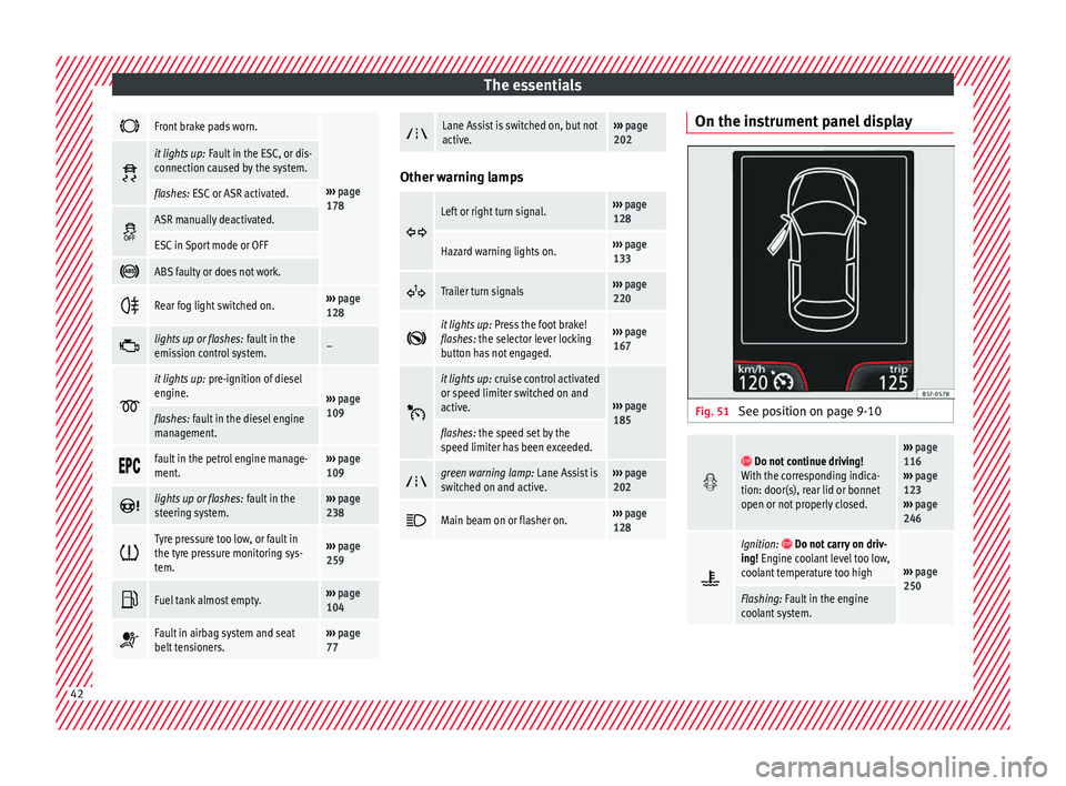
128 On the instrument panel display
Fig. 51
See position on page 9-10
Do not continue driving!
With the corresponding indica-
tion: door(s), rear lid or bonnet
open or not properly closed.››› page
116
››› page
123
››› page
246
Ignition: Do not carry on driv-
ing! Engine coolant level too low,
coolant temperature too high
››› page
250
Flashing: Fault in the engine
coolant system. 42
Page 45 of 308
The essentials
Do not continue driving!
Engine oil pressure too low. If
the warning lamp flashes, stop
driving, even if the oil level is
correct. Do not even run the en-
gine at idle speed!
››› page
248
Fault in the battery.›››
page
253
Driving light totally or partially
faulty.›››
page
94
Fault in the cornering light sys-
tem.››› page
128
Diesel particulate filter blocked›››
page
176
Level of windscreen washer fluid
too low.›››
page
136
Flashing: Fault in the oil level de-
tection. Control manually.›››
page
248
Ignition: Insufficient engine oil.
Fault in the gearbox.›››
page
174
Light Assist on.›››
page
130
Immobiliser active.
Service interval display›››
page
38
Mobile telephone is connected
via Bluetooth to the original tele-
phone device.›››
Book-
let Radio
or
››› Book-
let Navi-
gation
system
Mobile telephone battery charge
meter. Available only for devices
pre-installed in factory.
Freezing warning. The outside
temperature is lower than +4°C
(+39°F).›››
page
33
Start-Stop system activated.›››
page
183
Start-Stop system unavailable.
Low consumption driving status›››
page
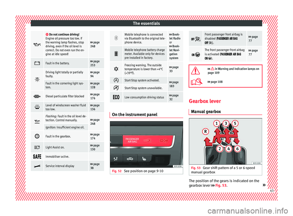
32 On the instrument panel
Fig. 52
See position on page 9-10
Front passenger front airbag is
disabled (
).
››› page
77
The front passenger front airbag
is activated (
).
››› page
77
››› in Warning and indication lamps on
page 109
››› page 108 Gearbox lever
M anua
l
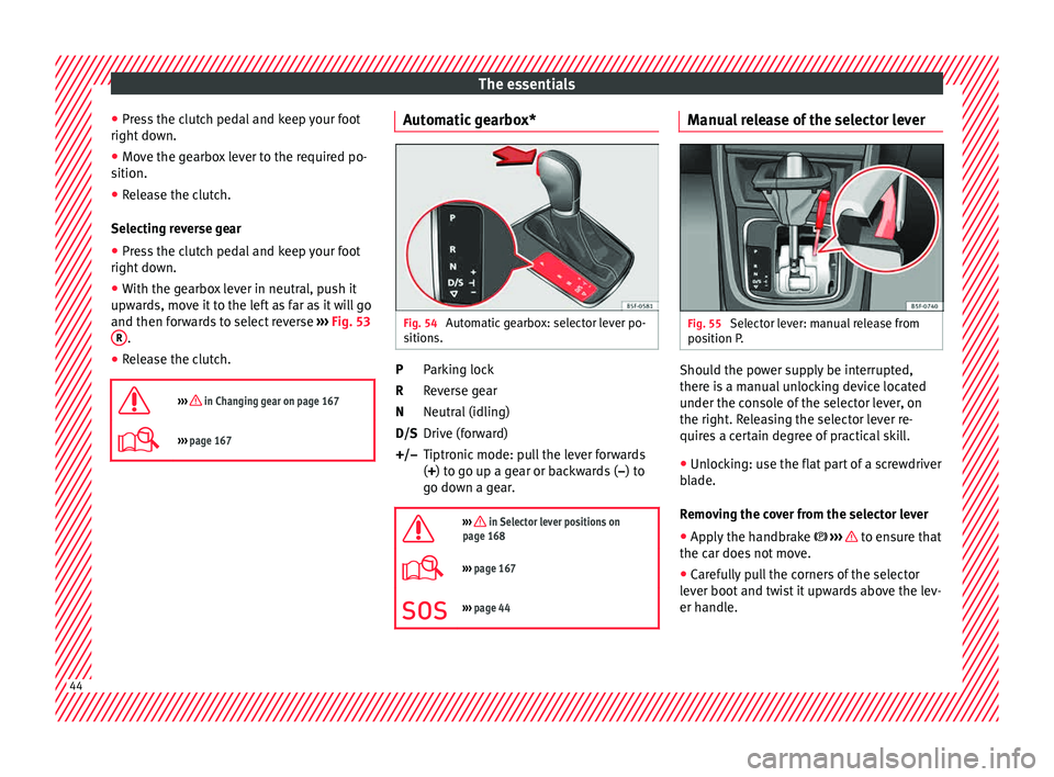
gearbox Fig. 53
Gear shift pattern of a 5 or 6-speed
m anual
g
earbox The position of the gears is indicated on the
g
e
arbo
x lever ››› Fig. 53. » 43
Page 46 of 308
The essentials
● Pr e
s
s the clutch pedal and keep your foot
right down.
● Move the gearbox lever to the required po-
sition.
● Rel
ease the clutch.
Selecting r
everse gear
● Press the clutch pedal and keep your foot
right down.
● W
ith the gearbox lever in neutral, push it
upwar
ds, move it to the left as far as it will go
and then forwards to select reverse ››› Fig. 53
R .
● Release the clutch.
››› in Changing gear on page 167
››› page 167 Automatic gearbox*
Fig. 54
Automatic gearbox: selector lever po-
s ition
s. Parking lock
R
ev
er
se gear
Neutral (idling)
Drive (forward)
Tiptronic mode: pull the lever forwards
(+) to go up a gear or backwards ( –) to
go down a gear.
››› in Selector lever positions on
page 168
››› page 167
››› page 44 P
R
N
D/S
+/–
Manual release of the selector lever Fig. 55
Selector lever: manual release from
po s
ition P
. Should the power supply be interrupted,
ther
e i
s
a manual unlocking device located
under the console of the selector lever, on
the right. Releasing the selector lever re-
quires a certain degree of practical skill.
● Unlocking: use the flat part of a screwdriver
bla
de.
Removing the cover from the selector lever
● Apply the handbrake ›››
to ensure that
the c ar doe
s
not move.
● Carefully pull the corners of the selector
lever boot
and twist it upwards above the lev-
er handle. 44
Page 47 of 308
The essentials
Releasing the selector lever
● Using a screwdriver, press and hold the yel-
lo w u
n
locking tab sideways ››› Fig. 55.
● Now press the interlock button on the se-
lector l
ever A and move the selector lever to
po s
ition
N.
● After carrying out the manual release, at-
tach the sel
ector lever boot on the gearbox
console again. If the power supply should ever fail (e.g. dis-
char
ged battery) and the vehicle has to be
pushed or towed, the selector lever must first
be moved to position N, after operating the
manual release mechanism. WARNING
The selector lever may be moved out of posi-
tion P only when the h
andbrake is firmly ap-
plied. If this does not work, secure the vehi-
cle with the brake pedal. On a slope the vehi- cle could otherwise start to move inadver-
tently
af
ter shifting the selector lever out of
position P - accident risk! Air conditioning
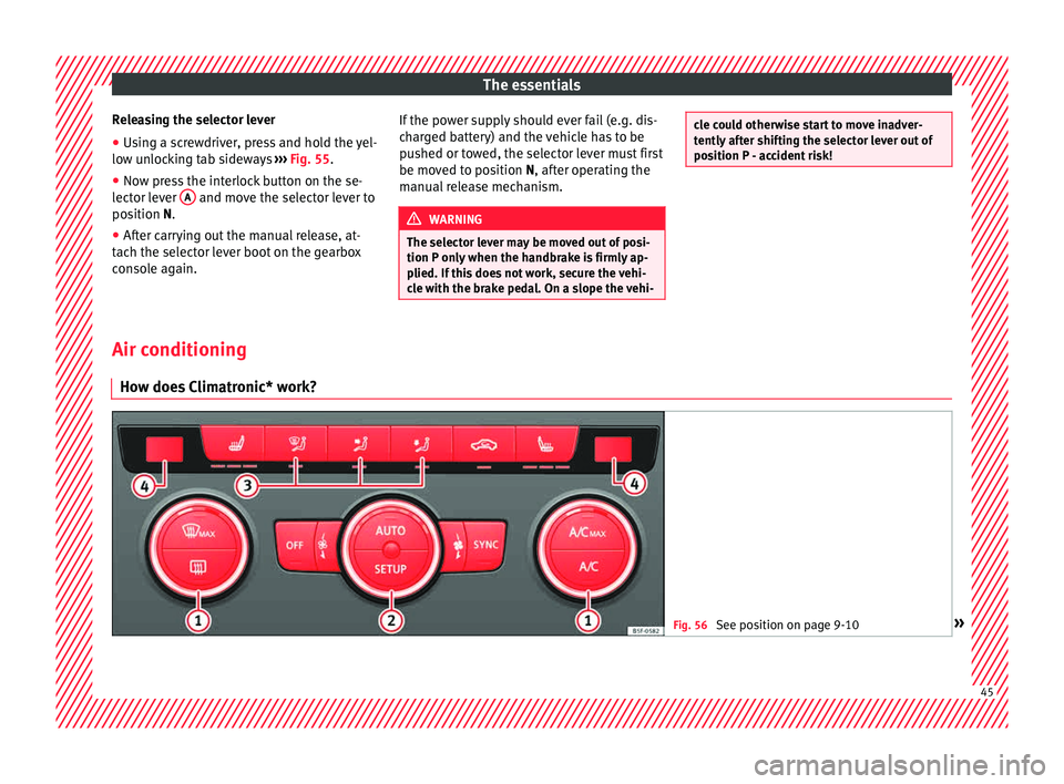
How doe s
Climatronic* work? Fig. 56
See position on page 9-10 » 45
Page 53 of 308
The essentials
Level control Fi l
lin
g capacities
Tank level
Petrol and diesel
engines50 l, of which, approx. 7 l reserveVehicles with all-wheel-drive :
55 l, of which, approx. 8.5 l re- serve
Natural gas en-
ginea)approx. 15 kg
a)
The capacity depends on the efficacy and characteristics of
the natural gas pumps. The capacity indicated is based on a
minimum loading pressure of 200 bar.
Capacity of the windscreen washer fluid container
Versions without
headlight washer
systemapprox. 3 litres
Versions with
headlight washer
systemapprox. 5 litres Fuel
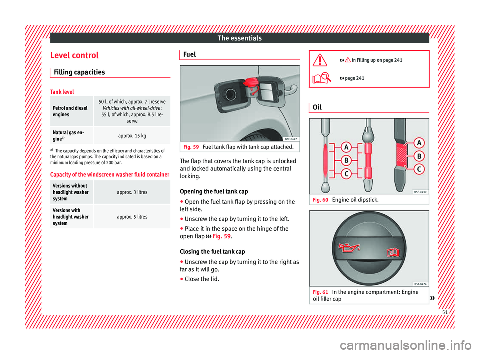
Fig. 59
Fuel tank flap with tank cap attached. The flap that covers the tank cap is unlocked
and loc
k
ed aut
omatically using the central
locking.
Opening the fuel tank cap
● Open the fuel tank flap by pressing on the
left
side.
● Unscrew the cap by turning it to the left.
● Place it in the space on the hinge of the
open flap ››
› Fig. 59.
Closing the fuel tank cap
● Unscrew the cap by turning it to the right as
far as
it will go.
● Close the lid.
››› in Filling up on page 241
›››
page 241 Oil
Fig. 60
Engine oil dipstick. Fig. 61
In the engine compartment: Engine
oi l
fi
ller cap » 51
Page 57 of 308
The essentials
Emergencies F u
se
s
Fuse location Fig. 65
On the driver-side dash panel: fuse
bo x
c
over Fig. 66
In the engine compartment: fuse box
c o
v
er Underneath the instrument panel
The f
use bo
x is located behind the storage
compartment ››› Fig. 65.
In the engine compartment
Press the locking tabs to release the fuse box
cover ››› Fig. 66.
Identifying fuses situated below the dash
panel by colours
ColourAmp rating
Black1
Purple3
Light brown5
Brown7.5
Red10
Blue15
Yellow20
White or transparent25
Green30
Orange40
››› in Introduction on page 91
›››
page 91 Replacing a blown fuse
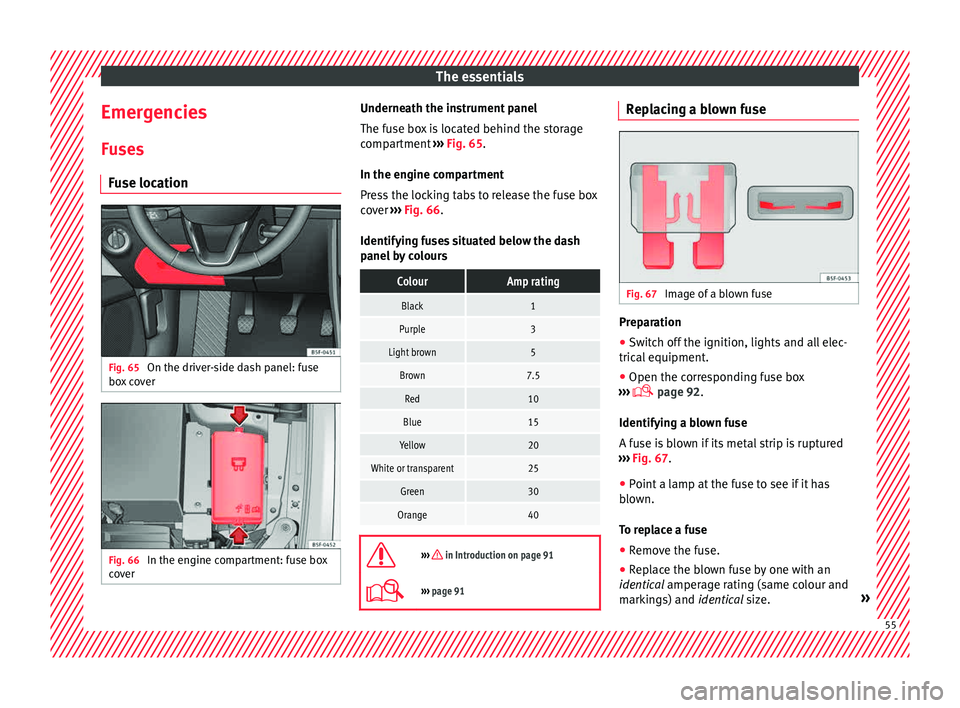
Fig. 67
Image of a blown fuse Preparation
● Switch off the ignition, lights and all elec-
tric al
equipment
.
● Open the corresponding fuse box
›››
page 92.
Identifying a blown fuse
A fuse is blown if its metal strip is ruptured
››› Fig. 67.
● Point a lamp at the fuse to see if it has
blown.
T
o replace a fuse
● Remove the fuse.
● Replace the blown fuse by one with an
identica
l amperage rating (same colour and
markings) and identical size. » 55
Page 58 of 308
The essentials
● Rep
l
ace the cover again or close the fuse
box lid.
Bulbs Bul
bs (12 V)
Light source used for each function
Halogen headlightsType
Daytime driving light/side lightP21W SLL
Dipped beam headlightsH7 LL
Main beam headlightsH7 LL
Turn signalPY21W LL
Full-LED main headlightsType
No bulbs may be replaced. All functions are with LEDs
Front fog lightType
Fog/cornering lights*H8
Rear lightsType
Brake light/tail lightP21W LL
Side lights2x W5W LL
Turn signalPY21W LL
Retro fog lightH21W
Rear lightsType
Reverse lightsP21W LL
LED rear lightsType
Turn signalPY21W LL
Retro fog lightH21W
Reverse lightsP21W LL
The remaining functions work with LEDs
›››
page 94 Action in the event of a punc-
t
ur
e
Wh
at to do first ●
Park the vehicle on a horizontal surface
and in a s af
e p
lace as far away from traffic as
possible.
● Apply the handbrake.
● Switch on the hazard warning lights.
● Manual gearbox: select the 1s
t gear.
● Automatic gearbox: Move the sel
ector lever
to position P.
● If you are towing a trailer, unhitch it from
your v
ehicle. ●
Have the v
ehicle tool kit ›››
page 86
and the spare wheel* ready
››› page 262.
● Observe the applicable legislation for each
countr
y (reflective vest, warning triangles,
etc.).
● All occupants should leave the vehicle and
wait in a s
afe place (for instance behind the
roadside crash barrier). WARNING
● Alw a
ys observe the above steps and pro-
tect yourself and other road users.
● If you change the wheel on a slope, block
the wheel on the oppo
site side of the car with
a stone or similar to prevent the vehicle from
moving. 56
Page 64 of 308
The essentials
Towline anchorages
Att ac
h the b
ar or rope to the towline ancho-
rages.
The towline anchorages are located under
the floor panel in the luggage compartment,
next to the vehicle tools ›››
page 86.
Screw the towline anchorage into the screw
connection ››› Fig. 76 o ››› Fig. 77 and tighten
it with the wheel brace.
Tow rope or tow bar
The tow bar offers increased safety and a
lower risk of damage.
The tow rope is recommended when there is
no tow bar. It must be elastic so that it does
not damage the vehicle.
Notes for the driver of the towing vehicle
● The tow rope must be taut before you drive
off.
● Rel
ease the clutch very carefully when start-
ing the v
ehicle (manual gearbox), or acceler-
ate gently (automatic gearbox).
Driving style
Towing requires some experience, especially
when using a tow rope. Both drivers should
realise how difficult it is to tow a vehicle. In-
experienced drivers should not attempt to
tow. Do not pull too hard with the towing vehicle
and take c
are to avoid jerking the tow rope.
When towing on an unpaved road, there is al-
ways a risk of overloading and damaging the
anchorage points.
Switch on the ignition so that the turn sig-
nals, windscreen wipers and windscreen
washer can work. Ensure that the steering
wheel is unlocked and moves freely.
Place the gear lever in neutral on vehicles
with a manual gearbox. With an automatic
gearbox, place the lever in N.
To brake, press the brake pedal firmly. The
brake servo does not work when the engine
is switched off.
The power steering only works when the igni-
tion is switched on and the vehicle is moving,
provided that the battery is sufficiently charg-
ed. Otherwise, it will need more force.
Ensure that the tow rope remains taut at all
times.
››› in General information on page 89
››› page 89 Tow-starting
If the engine will not start, first try starting it
us
in
g the battery of another vehicle
››› page 62. You should only attempt to tow-
start a vehicle if charging the battery does
not work. This is done by leveraging wheel
movement.
When tow-starting a vehicle with a petrol en-
gine, do not tow it more than a short dis-
tance, otherwise unburned fuel can enter the
catalytic converter.
● Engage 2nd or 3rd gear before moving off.
● Press the clutch and hold the pedal down.
● Switch the ignition on.
● Once both vehicles are moving, release the
clut c
h.
● As soon as the engine has started, press
the clutc
h and move the gear lever to neutral.
How to jump start Jump lea
ds The jump lead must have a sufficient wire
c
r
o
ss section.
If the engine fails to start because of a dis-
charged battery, the battery can be connec-
ted to the battery of another vehicle to start
the engine. 62
Page 65 of 308

The essentials
Jump leads must comply with standard DIN
72553 (see c ab
l
e manufacturer's instruc-
tions). The wire cross section must be at least
25 mm 2
for petrol engines and at least
35 mm 2
for diesel engines. Note
● The v ehic
les must not touch each other,
otherwise electricity could flow as soon as
the positive terminals are connected.
● The discharged battery must be properly
connected t
o the on-board network. How to jump start: description
Fig. 78
Diagram of connections for vehicles
w ithout
Start Stop system Fig. 79
Diagram of connections for vehicles
with St
art Stop system Jump lead terminal connections
1. Switch off the ignition of both vehicles
››
›
.
2. Connect one end of the re
d
jump lead to
the positive + terminal of the vehicle
w ith the fl
at
battery A
› ›
› Fig. 78 .
3. Connect the other end of the red
jump
lead to the positive terminal + in the ve-
hic l
e pr
oviding assistance B .
4. For vehicles without Start-Stop system:
connect
one end of
the black jump lead to
the negative terminal – of the vehicle
pr o
v
iding the current B
› ›
› Fig. 78 .
– For vehicles with Start-Stop system: con-
nect one end of
the black jump lead X to a
s uit
ab
le ground terminal, to a solid piece of
metal in the engine block, or to the engine
block itself ››› Fig. 79. 5. Connect the other end of the
black
jump
lead X to a solid metal component bolted
t o the en
gine b
lock or to the engine block
itself of the vehicle with the flat battery.
Do not connect it to a point near the bat-
tery A .
6. Position the leads in such a way that they cannot
c
ome into contact with any moving
parts in the engine compartment.
Starting
7. Start the engine of the vehicle with the boostin
g battery and let it run at idling
speed.
8. Start the engine of the vehicle with the flat batter
y and wait for 2 or 3 minutes until
the engine is running.
Removing the jump leads
9. Before you remove the jump leads, switch off the dipped be
am headlights if they are
switched on.
10.
Turn on the heater blower and heated rear
window in the vehicle with the flat battery.
This helps minimise voltage peaks which
are generated when the leads are discon-
nected.
11.When the engine is running, disconnect the lea
ds in reverse order to the details
given above. » 63
Page 70 of 308
Safety
the chest and the centre of the steering
wheel
››
› Fig. 83. If you are sitting closer than
25 cm, the airbag system cannot protect you
properly.
● If your physical constitution prevents you
from maint
aining the minimum distance of 25
cm, contact a specialised workshop. The
workshop will help you decide if special spe-
cific modifications are necessary.
● When driving, always hold the steering
wheel with both h
ands on the outside of the
ring at the 9 o'clock and 3 o'clock positions.
This reduces the risk of injury when the driver
airbag is triggered.
● Never hold the steering wheel at the 12
o'clock
position, or in any other manner (e.g.
in the centre of the steering wheel). In such
cases, if the airbag is triggered, you may sus-
tain injuries to the arms, hands and head.
● To reduce the risk of injury to the driver
during sud
den braking manoeuvres or an ac-
cident, never drive with the backrest tilted far
back! The airbag system and seat belts can
only provide optimal protection when the
backrest is in an upright position and the
driver is wearing his or her seat belt correct-
ly.
● Adjust the head restraint properly to ach-
ieve optima
l protection. Adjusting the steering wheel position
Read the additional information carefully
›› ›
page 17. WARNING
● Never a dju
st the position of the steering
wheel when the vehicle is moving, as this
could cause an accident.
● Move the lever up firmly so the steering
wheel pos
ition does not accidentally change
during driving. risk of accident!
● Make sure you are capable of reaching and
firmly ho
lding the upper part of the steering
wheel: risk of accident!
● If you adjust the steering wheel so that it
points t
owards your face, the driver airbag
will not protect you properly in the event of
an accident. Make sure that the steering
wheel points towards your chest. Correct sitting position for front pas-
sen
g
er For your own safety and to reduce the risk of
injur
y
in the ev
ent of an accident, we recom-
mend the following adjustments for the front
passenger:
– Move the front passenger seat back as far
as po
ssible ››› .–
Mo v
e the se
at backrest to an upright posi-
tion so that your back rests completely
against it.
– Adjust the head restraint so that its upper
edge is
at the same level as the top of your
head, or as close as possible to the same
level as the top of your head ››› page 70.
– Always keep both feet in the footwell in
front of
the front passenger seat.
– Fasten your seat belt securely ›››
page 72.
It is possible to deactivate the front passen-
ger airbag in exceptional circumstances
››› page 81.
Adjusting the front passenger seat
››› page 140. WARNING
● An incorr ect
sitting position of the front
passenger can lead to severe injuries.
● Adjust the front passenger seat so that
there is
at least 25 cm between your chest
and the dash panel. If you are sitting closer
than 25 cm, the airbag system cannot protect
you properly.
● If your physical constitution prevents you
from maint
aining the minimum distance of 25
cm, contact a specialised workshop. The
workshop will help you decide if special spe-
cific modifications are necessary.
● Always keep your feet in the footwell when
the vehic
le is moving; never rest them on the68