steering Seat Leon 5D 2015 Owner's Guide
[x] Cancel search | Manufacturer: SEAT, Model Year: 2015, Model line: Leon 5D, Model: Seat Leon 5D 2015Pages: 308, PDF Size: 5.93 MB
Page 94 of 308
Emergencies
●
Never u se a f
use with a higher value. Only
replace fuses with a fuse of the same amper-
age (same colour and markings) and size.
● Never repair a fuse.
● Never replace a fuse by a metal strip, staple
or simil
ar. CAUTION
● To pr ev
ent damage to the vehicle's electric
system, before replacing a fuse always turn
off the ignition, the lights and all electrical
elements and remove the key from the igni-
tion.
● If you replace a fuse with higher-rating
fuse,
you could cause damage to another part
of the electrical system.
● Protect the fuse boxes when open to pre-
vent the entr
y of dust or humidity as they can
damage the electrical system. Note
● One component m
ay have more than one
fuse.
● Several components may run on a single
fuse. Vehicle fuses
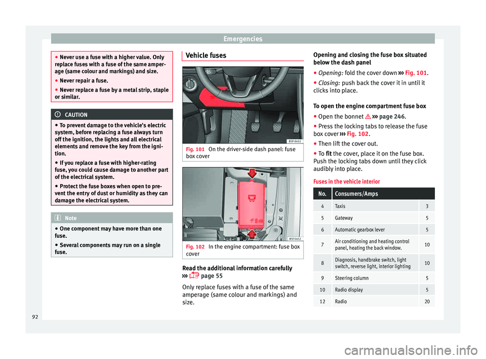
Fig. 101
On the driver-side dash panel: fuse
bo x
c
over Fig. 102
In the engine compartment: fuse box
c o
v
er Read the additional information carefully
› ›
›
page 55
Only replace fuses with a fuse of the same
amperage (same colour and markings) and
size. Opening and closing the fuse box situated
below the da
sh panel
● Opening: fold the cover down ››
› Fig. 101.
● Closing: push back the cover it in until it
clic
ks into place.
To open the engine compartment fuse box
● Open the bonnet ›››
page 246.
● Press the locking tabs to release the fuse
box c
over ››› Fig. 102.
● Then lift the cover out.
● To fit the cover, place it on the fuse box.
Pu
sh the locking tabs down until they click
audibly into place.
Fuses in the vehicle interior
No.Consumers/Amps
4Taxis3
5Gateway5
6Automatic gearbox lever5
7Air conditioning and heating control
panel, heating the back window.10
8Diagnosis, handbrake switch, light
switch, reverse light, interior lighting10
9Steering column5
10Radio display5
12Radio20 92
Page 105 of 308
Controls and displays
Operation
C ontr
o
ls and displays
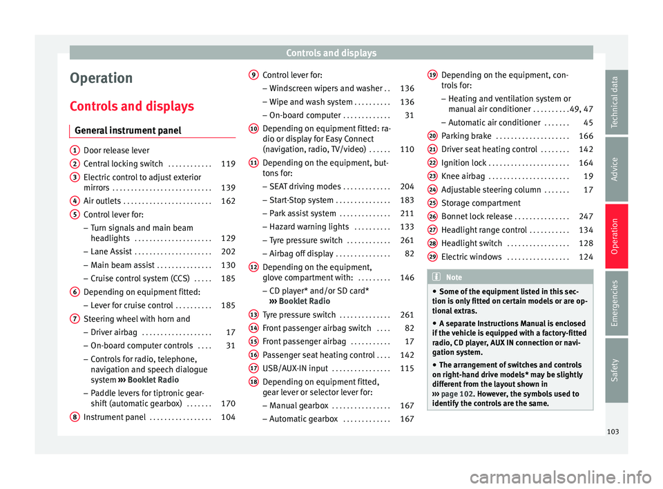
General instrument panel Door release lever
Centr
al
locking switch . . . . . . . . . . . .119
Electric control to adjust exterior
mirrors . . . . . . . . . . . . . . . . . . . . . . . . . . . 139
Air outl
ets . . . . . . . . . . . . . . . . . . . . . . . . 162
Control lever for:
– Turn s ign
als and main beam
headlights . . . . . . . . . . . . . . . . . . . . . 129
– Lane Ass i
st . . . . . . . . . . . . . . . . . . . . . 202
– Main beam a
ssist . . . . . . . . . . . . . . . 130
– Cruise c
ontrol system (CCS) . . . . .185
Depending on equipment fitted:
– Lev er f
or cruise control . . . . . . . . . .185
Steering wheel with horn and – Driver airbag . . . . . . . . . . . . . . . . . . . 17
– On-boar d c
omputer controls . . . .31
– Contro
ls for radio, telephone,
navigation and speech dialogue
system ›››
Booklet Radio
– Paddle levers for tiptronic gear-
shift (automatic gearbox) . . . . . . .170
Instrument panel . . . . . . . . . . . . . . . . . 104
1 2
3
4
5
6
7
8 Control lever for:
– Wind
s
creen wipers and washer . .136
– Wipe and wa
sh system . . . . . . . . . . 136
– On-board c
omputer . . . . . . . . . . . . . 31
Depending on equipment fitted: ra-
dio or disp
lay for Easy Connect
(navigation, radio, TV/video) . . . . . .110
Depending on the equipment, but-
tons
for:
– SEAT driving modes . . . . . . . . . . . . .204
– Star t
-Stop system . . . . . . . . . . . . . . . 183
– Park a
ssist system . . . . . . . . . . . . . . 211
– Hazard w
arning lights . . . . . . . . . .133
– Tyr
e pressure switch . . . . . . . . . . . .261
– Airbag off di
splay . . . . . . . . . . . . . . . 82
Depending on the equipment,
glov e c
ompartment with: . . . . . . . . .146
– CD pl a
yer* and/or SD card*
››› Booklet Radio
Tyre pressure switch . . . . . . . . . . . . . .261
Front passenger airbag switch . . . .82
Front passenger airbag . . . . . . . . . . .17
Passenger seat heating control . . . .142
USB/AUX-IN input . . . . . . . . . . . . . . . . 115
Depending on equipment fitted,
ge ar l
ever or selector lever for:
– Manual gearbox . . . . . . . . . . . . . . . . 167
– Autom atic
gearbox . . . . . . . . . . . . . 167
9
10
11
12
13
14
15
16
17
18 Depending on the equipment, con-
tr
o
l
s for:
– Heating and ventilation system or
manual air conditioner . . . . . . . . . .49, 47
– Automatic
air conditioner . . . . . . .45
Parking brake . . . . . . . . . . . . . . . . . . . . 166
Driver seat heating control . . . . . . . .142
Ignition lock . . . . . . . . . . . . . . . . . . . . . . 164
Knee airbag . . . . . . . . . . . . . . . . . . . . . . 19
Adjustable steering column . . . . . . .17
Storage compartment
Bonnet lock
release . . . . . . . . . . . . . . . 247
Headlight range control . . . . . . . . . . .134
Headlight switch . . . . . . . . . . . . . . . . . 128
Electric windows . . . . . . . . . . . . . . . . . 124 Note
● Some of the equipment li
sted in this sec-
tion is only fitted on certain models or are op-
tional extras.
● A separate Instructions Manual is enclosed
if the v
ehicle is equipped with a factory-fitted
radio, CD player, AUX IN connection or navi-
gation system.
● The arrangement of switches and controls
on right-hand driv
e models* may be slightly
different from the layout shown in
››› page 102. However, the symbols used to
identify the controls are the same. 19
20
21
22
23
24
25
26
27
28
29
103
Technical data
Advice
Operation
Emergencies
Safety
Page 113 of 308
Communications and multimedia
Communications and multi-
medi a
St eerin
g wheel controls*
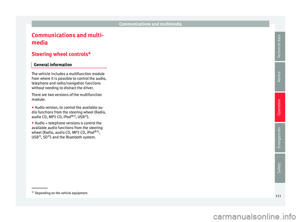
General information The vehicle includes a multifunction module
from wher
e it
is possible to control the audio,
telephone and radio/navigation functions
without needing to distract the driver.
There are two versions of the multifunction
module:
● Audio version, to control the available au-
dio fu nction
s from the steering wheel (Radio,
audio CD, MP3 CD, iPod ®1)
, USB 1)
).
● Audio + telephone versions o control the
avail
able audio functions from the steering
wheel (Radio, audio CD, MP3 CD, iPod ®1)
,
USB 1)
, SD 1)
) and the Bluetooth system. 1)
Depending on the vehicle equipment.
111
Technical data
Advice
Operation
Emergencies
Safety
Page 114 of 308

Operation
Operating the audio system Fig. 128
Controls on the steering wheel.ButtonRadioMedia (except AUX)AUX
A TurnUp/down volumeUp/down volumeUp/down volume
A PressNo functionNo functionNo function
BMutePauseMute
CSearch for last stationShort press: switch to the previous song
Hold down: quick rewindNo function
DSearch for the next stationShort press: switch to the next song
Hold down: fast forwardNo function
EPrevious presetPrevious folderNo function
FNext preset stationNext folderNo function
GChange sourceChange sourceChange source
H TurnSwitch MFA functionSwitch MFA functionSwitch MFA function
H PressActs on the MFAActs on the MFAActs on the MFA 112
Page 115 of 308
Communications and multimedia
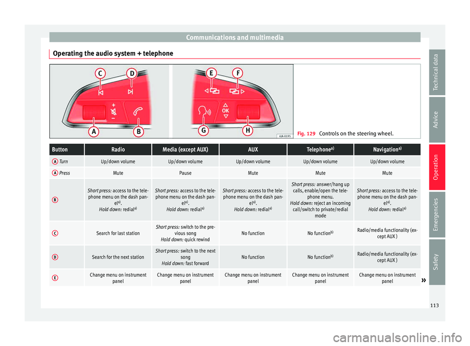
Operating the audio system + telephone Fig. 129
Controls on the steering wheel.ButtonRadioMedia (except AUX)AUXTelephone a)Navigation a)
A TurnUp/down volumeUp/down volumeUp/down volumeUp/down volumeUp/down volume
A PressMutePauseMuteMuteMute
B
Short press:
access to the tele-
phone menu on the dash pan- ela)
.
Hold down: redial a)Short press:
access to the tele-
phone menu on the dash pan- ela)
.
Hold down: redial a)Short press:
access to the tele-
phone menu on the dash pan- ela)
.
Hold down: redial a)Short press:
answer/hang up
calls, enable/open the tele- phone menu.
Hold down: reject an incoming call/switch to private/redial modeShort press: access to the tele-
phone menu on the dash pan- ela)
.
Hold down: redial a)
CSearch for last stationShort press:
switch to the pre-
vious song
Hold down: quick rewindNo functionNo function b)Radio/media functionality (ex-
cept AUX )
DSearch for the next stationShort press: switch to the next
song
Hold down: fast forwardNo functionNo function b)Radio/media functionality (ex-
cept AUX )
EChange menu on instrument panelChange menu on instrumentpanelChange menu on instrumentpanelChange menu on instrumentpanelChange menu on instrumentpanel» 113
Technical data
Advice
Operation
Emergencies
Safety
Page 136 of 308
Operation
Motorway light* The motorway light is available on vehicles
equipped w
ith f
ull-LED lights.
The function is connected/disconnected via
the corresponding Easy Connect system
menu.
● Activation: when going abo
ve 110 km/h for
more than 30 seconds, the dipped beam rai-
ses slightly to increase the distance of visibil-
ity of the driver.
● Deactivation: when reduc in
g the speed of
the car below 100 km/h, the dipped beam re-
turns to its normal position.
Driving abroad The light beam of the dipped beam lights is
a
symmetric: the s
ide of
the road on which
you are driving is lit more intensely.
When a car that is manufactured in a country
that drives on the right travels to a country
that drives on the left (or vice versa), it is nor-
mally necessary to cover part of the headlight
bulbs with stickers or to change the adjust-
ment of the headlights to avoid dazzling oth-
er drivers.
In such cases, the regulations specify certain
light values that must be complied with for
designated points of the light distribution.
This is known as “Tourist light”. The light distribution that the halogen and
ful
l-LED headlights of the SEAT Leon range
have allows the specific “tourist light” values
to be met without the need for stickers or
changes in the settings. Note
“Tourist light” is only allowed temporarily. If
you ar e p
lanning a long stay in a country that
drives on the other side, you should take the
vehicle to an Authorised Technical Service to
change the headlights. Headlight range control, lighting of
the in
s
trument
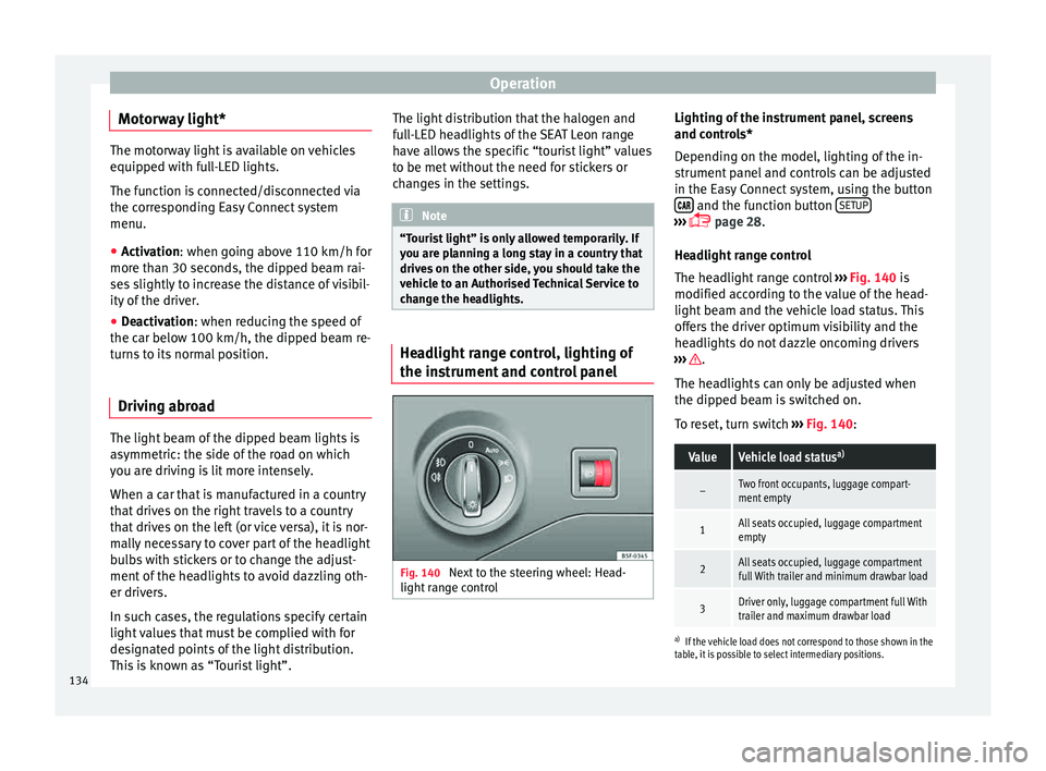
and control panel Fig. 140
Next to the steering wheel: Head-
light r
an
ge control Lighting of the instrument panel, screens
and c
ontr
o
ls*
Depending on the model, lighting of the in-
strument panel and controls can be adjusted
in the Easy Connect system, using the button and the function button
S
ETUP ›››
p
age 28.
He a
dlight range control
The headlight range control ››› Fig. 140 is
modified according to the value of the head-
light beam and the vehicle load status. This
offers the driver optimum visibility and the
headlights do not dazzle oncoming drivers
››› .
The he a
dlights
can only be adjusted when
the dipped beam is switched on.
To reset, turn switch ››› Fig. 140:
ValueVehicle load status a)
–Two front occupants, luggage compart-
ment empty
1All seats occupied, luggage compartment
empty
2All seats occupied, luggage compartment
full With trailer and minimum drawbar load
3Driver only, luggage compartment full With
trailer and maximum drawbar load
a)
If the vehicle load does not correspond to those shown in the
table, it is possible to select intermediary positions.
134
Page 139 of 308
Lights and visibility
Windscreen wiper functionsWindscreen wiper performance in different sit-
uations
If the vehicle is at a
standstillThe activated position provision-
ally changes to the previous posi-
tion.
During automatic
wipe
The air conditioner comes on for
approximately 30 seconds in air
recirculation mode to prevent the
smell of the windscreen washer
fluid entering the inside the vehi-
cle.
For the interval wipe
Intervals between wipes depend
on the vehicle's speed. The high-
er the vehicle speed the shorter
the intervals. Heated windscreen washer jets
The he
atin
g on
ly thaws the frozen jets, it
does not thaw the water in the washer hoses.
When the ignition is switched on the heated
windscreen washer jets automatically adjust
the heat depending on the ambient tempera-
ture.
Headlight wash/wipe system
The headlight washers/wipers clean the
headlight lenses.
After the ignition is switched on, the first and
every fifth time the windscreen washer is
switched on, the headlights are also washed. Therefore, the windscreen wiper lever should
be pul
led towards the steering wheel when
the dipped beam or main beam are on. Any
incrusted dirt (such as insects) should be
cleaned regularly (e.g. when refuelling).
To ensure the headlight washers work cor-
rectly in winter, any snow which has got into
the bumper jet supports should be cleaned
away. If necessary, remove snow with an anti-
icing spray. Note
The wiper will try to wipe away any obstacles
that ar
e on the windscreen. The wiper will
stop moving if the obstacle blocks its path.
Remove the obstacle and switch the wiper
back on again. Rain sensor*
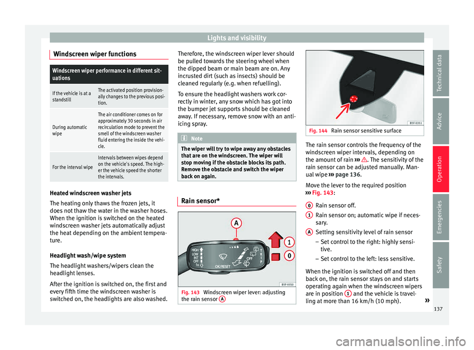
Fig. 143
Windscreen wiper lever: adjusting
the r ain sen
sor A Fig. 144
Rain sensor sensitive surface The rain sensor controls the frequency of the
w
ind
s
creen wiper intervals, depending on
the amount of rain ››› . The sensitivity of the
r ain sen
sor c
an be adjusted manually. Man-
ual wipe ››› page 136.
Move the lever to the required position
››› Fig. 143:
Rain sensor off.
Rain sensor on; automatic wipe if neces-
sary.
Setting sensitivity level of rain sensor
– Set control to the right: highly sensi-
tive.
– Set control to the left: less sensitive.
When the ignition is switched off and then
back on, the rain sensor stays on and starts
operating again when the windscreen wipers
are in position 1 and the vehicle is travel-
lin g at
mor
e than 16 km/h (10 mph). »
0 1
A
137
Technical data
Advice
Operation
Emergencies
Safety
Page 167 of 308
Driving
WARNING
● Never ru n the en
gine in confined spaces, as
the exhaust gases are poisonous. CAUTION
Avoid high engine speeds, full throttle and
extr eme lo
ad conditions until the engine has
reached its normal operating temperature,
otherwise this can damage the engine. For the sake of the environment
Do not warm up the engine by idling it. You
shoul d driv
e off as soon as you start the en-
gine. This will help avoid unnecessary ex-
haust emissions. Note
● If it i
s difficult to turn the ignition key to
the position 1 , turn the steering wheel to
both side s
to release the steering lock.
● When starting from cold, the engine may be
a little noisy
for the first few seconds until oil
pressure has built up in the hydraulic valve
lifters. This is quite normal, and no cause for
concern.
● If the vehicle battery is disconnected and
reconnect
ed, the key must remain in the posi-
tion 1 for around 5 seconds before starting
up.
● Vehic
les with automatic gearbox: after
switc
hing off the ignition, you can only re-
move the ignition key if the selector lever is in position “P” (parking lock). Next, the se-
lect
or l
ever is locked. Switching off the engine with the key
Switching off the engine
– Stop the vehicle.
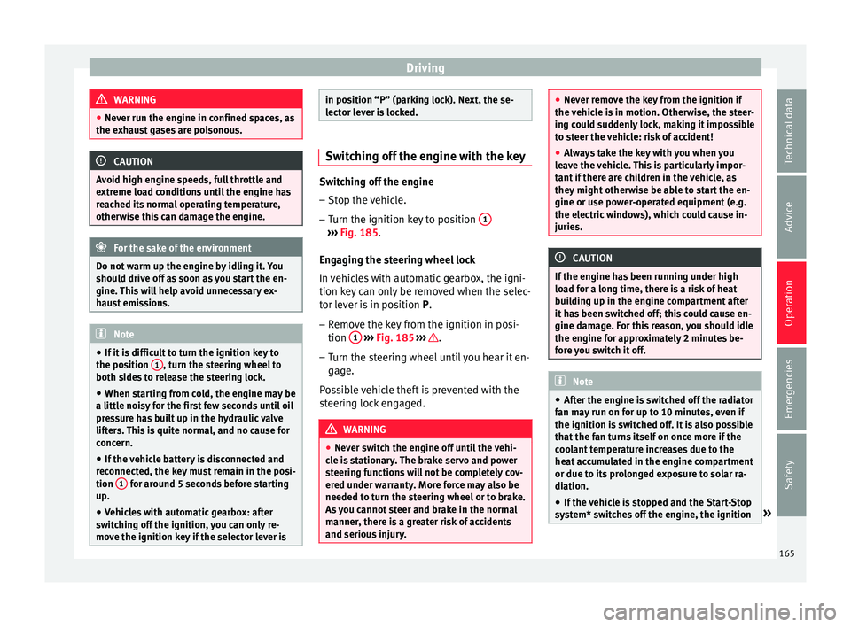
– Turn the ignition key to position 1 ›››
Fig. 185.
Eng agin
g the steering wheel lock
In vehicles with automatic gearbox, the igni-
tion key can only be removed when the selec-
tor lever is in position P.
– Remove the key from the ignition in posi-
tion 1
› ›
› Fig. 185
››› .
– Turn the steering wheel until you hear it en-
gag
e.
P
ossible vehicle theft is prevented with the
steering lock engaged. WARNING
● Never sw it
ch the engine off until the vehi-
cle is stationary. The brake servo and power
steering functions will not be completely cov-
ered under warranty. More force may also be
needed to turn the steering wheel or to brake.
As you cannot steer and brake in the normal
manner, there is a greater risk of accidents
and serious injury. ●
Never r emo
ve the key from the ignition if
the vehicle is in motion. Otherwise, the steer-
ing could suddenly lock, making it impossible
to steer the vehicle: risk of accident!
● Always take the key with you when you
leav
e the vehicle. This is particularly impor-
tant if there are children in the vehicle, as
they might otherwise be able to start the en-
gine or use power-operated equipment (e.g.
the electric windows), which could cause in-
juries. CAUTION
If the engine has been running under high
loa d f
or a long time, there is a risk of heat
building up in the engine compartment after
it has been switched off; this could cause en-
gine damage. For this reason, you should idle
the engine for approximately 2 minutes be-
fore you switch it off. Note
● Aft er the en
gine is switched off the radiator
fan may run on for up to 10 minutes, even if
the ignition is switched off. It is also possible
that the fan turns itself on once more if the
coolant temperature increases due to the
heat accumulated in the engine compartment
or due to its prolonged exposure to solar ra-
diation.
● If the vehicle is stopped and the Start-Stop
syst
em* switches off the engine, the ignition » 165
Technical data
Advice
Operation
Emergencies
Safety
Page 168 of 308

Operation
remains switched on. Make sure that the igni-
tion is
sw
itched off before leaving the
vehicle, otherwise the battery could dis-
charge. Braking and parking
Us in
g the handbrake Fig. 186
Handbrake between the front seats. The handbrake should be applied firmly to
pr
ev
ent
the vehicle from accidentally rolling
away.
Always apply the handbrake when you leave
your vehicle and when you park.
Applying the handbrake
– Pull the handbrake lever up firmly
›››
Fig. 186. Releasing the handbrake
– Pull the lever up slightly and press the re-
lea
se knob in the direction of the arrow
››› Fig. 186 and guide the handbrake lever
down fully ››› .
A lw
a
ys pull the handbrake all the way up, so
there is less risk of driving off with it still en-
gaged ››› .
The h andbr
ak
e warning lamp lights up
when the handbrake is applied and the igni-
tion switched on. The warning lamp turns off
when the handbrake is released.
If you drive faster than 6 km/h (4 mph) with
the handbrake on, the following message*
will appear on the instrument panel display: HANDBRAKE ON. You will also hear an audi-
ble warning. WARNING
● Never u se the h
andbrake to stop the vehi-
cle when it is in motion. The braking distance
is considerably longer, because braking is
only applied to the rear wheels. Risk of acci-
dent!
● If the handbrake is only partially released,
this w
ill cause the rear brakes to overheat,
which can impair the function of the brake
system and could lead to an accident. This al-
so causes premature wear on the rear brake
pads. CAUTION
Always apply the handbrake before you leave
the v ehic
le. Put it in 1st gear as well. Parking
The handbrake should always be firmly ap-
plied when the
v
ehicle is parked.
Always note the following points when park-
ing the vehicle: – Use the brake pedal to stop the vehicle.
– Apply the handbrake.
– Put it in 1st gear.
– Switch the engine off and remove the key
from the ignition. T
urn the steering wheel
slightly to engage the steering lock.
– Never leave a vehicle key in the vehicle.
Additiona
l notes on parking the vehicle on
gradients:
Turn the steering wheel so that the vehicle
rolls against the kerb if it started to roll.
● If the vehicle is parked facing downhil
l,
turn the front wheels so that they point to-
wards the kerb .
● If the vehicle is parked facing uphill
, turn
the front wheels so that they point away from
the kerb.
166
Page 172 of 308

Operation
Note
● If the sel ect
or lever lock does not engage,
there is a fault. The transmission is interrup-
ted to prevent the vehicle from accidentally
moving. Follow the procedure below in order
for the selector lever lock to engage again:
–With a 6-speed gearbox: press the brake
pedal and release it again.
– With a 7-speed gearbox: press the brake
pedal. Move the selector lever to posi-
tion P or N and subsequently engage a
gear.
● Despite a gear being engaged, the vehicle
does not
move forwards or back. Proceed to
the next mode:
– When the vehicle does not move in the
required direction, the system may not
have the gear range correctly engaged.
Press the brake pedal and engage the
gear range again.
– If the vehicle still does not move in the
required direction, there is a system mal-
function. Seek specialist assistance and
have the system checked. Changing gears in tiptronic mode*
Fig. 188
Centre console: changing gear with
tiptr onic Fig. 189
Steering wheel: automatic gearbox
l ev er
s The tiptronic gives the driver the option to
c
h
an
ge gears manually. Changing gear manually with the selector
lever
It
is possible to change to tiptronic mode,
both when the vehicle is stopped and while
driving.
– To switch to tiptronic mode, move the se-
lector l
ever from position D/S to the right.
As soon as the change is made the selector
level will be shown in the position M on the
instrument panel display (for example M4
means that the fourth gear is engaged).
– Move the selector lever forwards + to se-
l ect
a higher g
ear ››› Fig. 188.
– Move the selector lever backwards – to
sel ect
a lo
wer gear.
Changing gear manually with the gearshift
paddles*
The gearshift paddles can be used when the
selector lever is in the position D/S or M.
– Press the gearshift paddle + to select a
higher g e
ar ›
›› Fig. 189.
– Press the gearshift paddle – to select a
lo w
er g
ear.
– With the selector lever in position D/S, if no
pad
dle is operated during a short period of
time, the gearbox control system switches
back to automatic mode. To switch to per-
manent manual gear change using the
gearshift paddles, move the selector lever
from position D/S to the right.
170