tow Seat Leon 5D 2015 Owner's Guide
[x] Cancel search | Manufacturer: SEAT, Model Year: 2015, Model line: Leon 5D, Model: Seat Leon 5D 2015Pages: 308, PDF Size: 5.93 MB
Page 124 of 308
Operation
alarm is activated immediately on opening
the door).
● A door is opened.
● The bonnet is opened.
● The rear lid is opened.
● When the ignition is switched on with a
non- authori
sed k
ey.
● When the vehicle battery is disconnected.
● Movement inside the vehicle (in vehicles
with interior monit
oring ››› page 123).
● When the vehicle is towed (in vehicles with
anti-tow sy
stem ››› page 123).
● When the vehicle is raised (in vehicles with
anti-tow sy
stem ››› page 123).
● When the vehicle is transported on a ferry
or by r
ail (vehicles with an anti-tow system or
vehicle interior monitoring ››› page 123).
● When a trailer connected to the anti-theft
alarm sys
tem is disconnected.
How to turn OFF the alarm
Unlock the vehicle with the unlocking button
on the key or turn on the ignition with a valid
key. Note
● Aft er 28 d
ays, the indicator light will be
switched off to prevent the battery from ex-
hausting if the vehicle has been left parked for a long period of time. The alarm system
rem
ain
s activated.
● If, after the audible warning goes off, an-
other monitored ar
ea is accessed (e.g. the
rear lid is opened after a door has been
opened), the alarm is triggered again.
● The anti-theft alarm is not activated when
the vehic
le is locked from within using the
central locking button .
● If the driver door is unlocked mechanically
with the k ey
, only the driver door is unlocked,
the rest of the doors remain locked. Only
when the ignition has been turned on will the
other doors be available - but not unlocked -
and the central lock button will be activated.
● If the vehicle battery is run down or flat
then the anti-theft a
larm will not operate cor-
rectly.
● Vehicle monitoring remains active even if
the batter
y is disconnected or not working for
any reason.
● The alarm is triggered immediately if one of
the batter
y cables is disconnected while the
alarm system is active. Vehicle interior monitoring and anti-
t
o
w sy
stem* It is a monitoring or control function incorpo-
r
at ed in the anti-thef
t alarm* which detects
unauthorised vehicle entry by means of ultra-
sound. Activation
– It is automatically switched on when the
anti-theft al
arm is activated.
Deactivation – Open the vehicle with the key, either me-
chanic
ally or by pressing the button on
the r emot
e c
ontrol. The time period from
when the door is opened until the key is in-
serted in the contact should not exceed 15
seconds, otherwise the alarm will be trig-
gered.
– Press the button on the remote control
tw ic
e.
The volumetric sensor and tilt sen-
sors will be deactivated. The alarm system
remains activated.
The vehicle interior monitoring and the anti-
tow system are automatically switched on
again next time the vehicle is locked.
The vehicle interior monitoring and anti-tow
sensor (tilt sensor) are automatically switch-
ed on when the anti-theft alarm is switched
on. In order to activate it, all the doors and
the rear lid must be closed.
If you wish to switch off the vehicle interior
monitoring and the anti-tow system, it must
be done each time that the vehicle is locked;
if not, they will be automatically switched on.
The vehicle interior monitoring and the anti-
tow system should be switched off if animals
are left inside the locked vehicle (otherwise,
122
Page 125 of 308
Opening and closing
their movements will trigger the alarm) or
when, f or e
x
ample, the vehicle is transported
or has to be towed with only one axle on the
ground.
False alarms
Interior monitoring will only operate correctly
if the vehicle is completely closed. Please ob-
serve related legal requirements.
The following cases may cause a false alarm:
● Open windows (partially or fully).
● Panoramic/tilting sunroof open (partially or
compl
etely).
● Movement of objects inside the vehicle,
such a
s loose papers, items hanging from
the rear vision mirror (air fresheners), etc. Note
● If the v
ehicle is relocked and the alarm is
activated without the volumetric sensor func-
tion, relocking will activate the alarm with all
its functions, except the volumetric sensor.
This function is reactivated when the alarm is
switched on again, unless it is deliberately
switched off.
● If the alarm has been triggered by the volu-
metric sensor
, this will be indicated by a
flashing of the warning lamp on the driver
door when the vehicle is opened. The flash is
different to the flash indicating the alarm is
activated. ●
The v ibr
ation of a mobile phone left inside
the vehicle may cause the vehicle interior
monitoring alarm to trigger, as both sensors
react to movements and shakes inside the ve-
hicle.
● If on activating the alarm, any door or the
rear lid i
s open, only the alarm will be activa-
ted. The vehicle interior monitoring and the
anti-tow system will only be activated once
all the doors are closed (including the rear
lid). Deactivating the vehicle interior moni-
t
orin
g and anti-t
ow systems* Fig. 136
Vehicle interior monitoring/tow-
a w
a
y protection button. When the vehicle is locked, the alarm will be
trig
g
er
ed if movements are detected in the
interior (e.g. by animals) or if the vehicle's in-
clination is changed (e.g. during transport).
You can prevent the alarm from being trig- gered accidentally by switching off the vehi-
cle int
erior monitoring and/or tow-away pro-
tection.
– To switch off the vehicle interior monitoring
and tow-
away protection, switch off the ig-
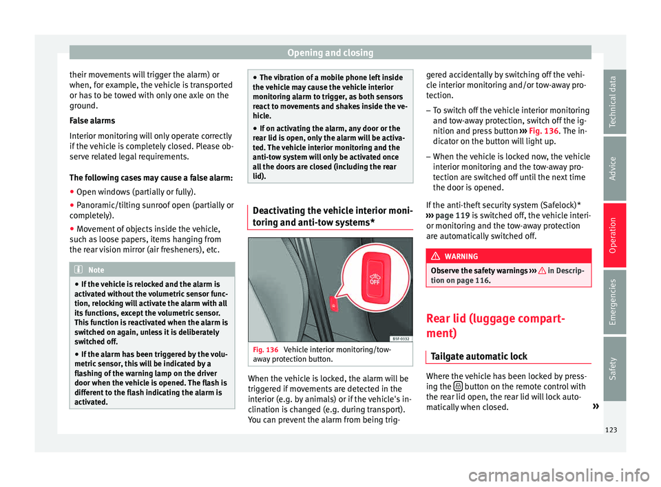
nition and press button ››› Fig. 136. The in-
dicator on the button will light up.
– When the vehicle is locked now, the vehicle
interior monitorin
g and the tow-away pro-
tection are switched off until the next time
the door is opened.
If the anti-theft security system (Safelock)*
››› page 119 is switched off, the vehicle interi-
or monitoring and the tow-away protection
are automatically switched off. WARNING
Observe the safety warnings ›››
in Descrip-
tion on pag e 116
. Rear lid (luggage compart-
ment)
Tai
l
gate automatic lock Where the vehicle has been locked by press-
in
g the button on the remote control with
the r ear lid open, the r
ear lid will lock auto-
matically when closed. »
123
Technical data
Advice
Operation
Emergencies
Safety
Page 132 of 308
Operation
●
If a tr ai
ler turn signal malfunctions, the
control lamp will stop flashing (trailer turn
signals) and the vehicle turn signal will flash
at double speed.
● The main beam headligh
ts can only be
switched on if the dipped beam headlights
are already on.
● In cold or damp weather conditions, the
headlight
s, tail lights and turn signals may
mist up inside temporarily. This is normal and
in no way effects the useful life of the vehicle
lighting system. Automatic dipped beam control
*The automatic dipped beam control is merely
int
ended a
s
an aid and is not able to recog-
nise all driving situations.
When the light switch is in position , the
vehicle lights and the instrument panel and
switch lighting switch on and off automatical-
ly in the following situations ››› in Daytime
ru nnin
g light
s on page 129:
Automatic switching
onAutomatic switching
off
The photo sensor detects
darkness, for example,
when driving through a
tunnel.When adequate lighting is
detected.
Automatic switching
onAutomatic switching
off
The rain sensor detects
rain and activates the
windscreen wipers.When the windscreen wip-
ers have been inactive for
a few minutes. WARNING
If the road is not well lit and other road users
cannot see the
vehicle well enough or at all,
accidents may occur.
● The automatic dipped beam control ( )
only sw
itches on the dipped beam when
there are no changes in brightness, and not,
for example when it is foggy. Main beam assist*
››
›
table on page 2
Main beam assist (Light Assist)
The main beam assist acts within the limits
of the system and depending on environmen-
tal and traffic conditions. Once switched on,
the system is activated as of a speed of
about 60 km/h (37 mph) and is deactivated
below about 30 km/h (18 mph) ››› .
When the sy s
t
em is activated and the camera
detects other vehicles that may be dazzled,
the main beam is automatically switched off.
Otherwise, the main beam is automatically
switched on. The main beam assist generally detects illu-
minated ar
eas and deactivates the main
beam when passing through a town, for ex-
ample.
Switching the main beam assist on and off
Func-
tionAction
Acti-
vate:
– Switch the ignition on and turn the light
switch to position .
– From the base position, move the main
beam and turn signal lever forwards
››› page 129. When the warning lamp
is
displayed on the instrument panel display,
the main beam assist is switched on.
To
switch
system off:
– Switch off the ignition.
– OR: turn the light switch to a different posi-
tion to
››› page 128.
– OR: with main beam on, move the main
beam and turn signal lever backwards.
– OR: move the main beam and turn the sig-
nal lever forwards to manually switch the
main beam on. The main beam assist will then
be deactivated. Malfunctions
The f
o
l
lowing conditions may prevent the
main beam headlight control from turning off
the headlights in time or from turning off al-
together:
● In poorly lit towns with highly reflective
signs.
130
Page 138 of 308

Operation
Options for adjusting driver and front pas-
sen g
er s
un visors:
● Lower the sun visor towards the wind-
scr
een.
● The sun visor can be pulled out of its
mounting and t
urned towards the door
››› Fig. 141 1 .
● Swing the sun visor towards the door, lon-
git udin
al
ly backwards.
Vanity mirror light
There may be a vanity mirror, with a cover, on
the rear of the sun visor. When the cover is
opened 2 a light comes on.
The l amp g
oe
s out when the vanity mirror
cover is closed or the sun visor is pushed
back up. WARNING
Folded sun blinds can reduce visibility.
● Always store sun blinds and visors in their
hous in
g when not in use. Note
The light above the sun visor automatically
swit c
hes off after a few minutes in certain
conditions. This prevents the battery from
discharging. Sun blind*
3 Applies to the model: LEON ST
Fig. 142
Rear window: sun blind. Rear window sun blind*
– Pull out the visor and hook it into the hooks
in the c entr
e of
the top of the door frame
››› Fig. 142.
Windscreen wiper and window
wiper sys
tems
Window wiper lever Read the additional information carefully
› ›
›
page 27 CAUTION
If the ignition is switched off with the wind-
sc r
een wipers active, they complete their wipe before returning to the rest position.
Ice, s
no
w and other obstacles on the wind-
screen may damage the wiper and the wind-
screen wiper motor.
● If necessary, remove snow and ice from the
winds
creen wipers before starting your jour-
ney.
● Carefully lift the frozen windscreen wipers
from the gla
ss. SEAT recommends a de-icer
spray for this operation.
● Do not switch on the windscreen wipers if
the winds
creen is dry. Cleaning with the
windscreen wipers while dry can cause dam-
age.
● In icy conditions, always check that the
wiper bl
ades are not frozen to the glass be-
fore using the wipers. In cold weather, it may
help to leave the vehicle parked with the wip-
ers in service position ›››
page 64. Note
● The wind s
creen and window wipers only
function when the ignition is switched on and
the bonnet or rear lid, respectively, are
closed.
● The interval wipe speed varies according to
the vehic
le speed. The faster the vehicle is
moving, the more often the windscreen is
cleaned.
● The rear wiper is automatically switched on
when the winds
creen wiper is on and the car
is in reverse gear. 136
Page 139 of 308
Lights and visibility
Windscreen wiper functionsWindscreen wiper performance in different sit-
uations
If the vehicle is at a
standstillThe activated position provision-
ally changes to the previous posi-
tion.
During automatic
wipe
The air conditioner comes on for
approximately 30 seconds in air
recirculation mode to prevent the
smell of the windscreen washer
fluid entering the inside the vehi-
cle.
For the interval wipe
Intervals between wipes depend
on the vehicle's speed. The high-
er the vehicle speed the shorter
the intervals. Heated windscreen washer jets
The he
atin
g on
ly thaws the frozen jets, it
does not thaw the water in the washer hoses.
When the ignition is switched on the heated
windscreen washer jets automatically adjust
the heat depending on the ambient tempera-
ture.
Headlight wash/wipe system
The headlight washers/wipers clean the
headlight lenses.
After the ignition is switched on, the first and
every fifth time the windscreen washer is
switched on, the headlights are also washed. Therefore, the windscreen wiper lever should
be pul
led towards the steering wheel when
the dipped beam or main beam are on. Any
incrusted dirt (such as insects) should be
cleaned regularly (e.g. when refuelling).
To ensure the headlight washers work cor-
rectly in winter, any snow which has got into
the bumper jet supports should be cleaned
away. If necessary, remove snow with an anti-
icing spray. Note
The wiper will try to wipe away any obstacles
that ar
e on the windscreen. The wiper will
stop moving if the obstacle blocks its path.
Remove the obstacle and switch the wiper
back on again. Rain sensor*
Fig. 143
Windscreen wiper lever: adjusting
the r ain sen
sor A Fig. 144
Rain sensor sensitive surface The rain sensor controls the frequency of the
w
ind
s
creen wiper intervals, depending on
the amount of rain ››› . The sensitivity of the
r ain sen
sor c
an be adjusted manually. Man-
ual wipe ››› page 136.
Move the lever to the required position
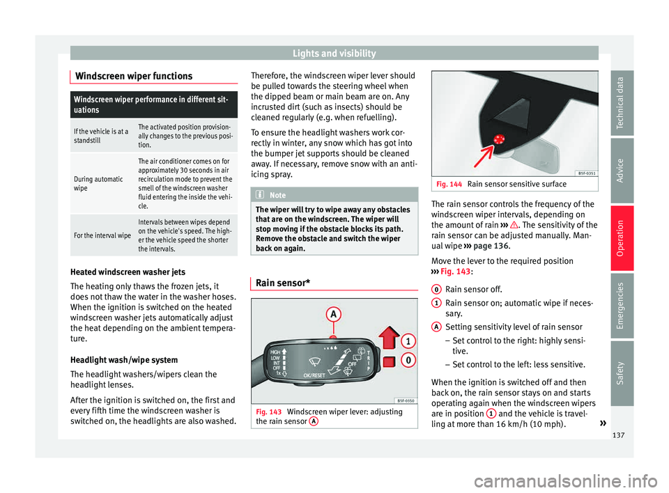
››› Fig. 143:
Rain sensor off.
Rain sensor on; automatic wipe if neces-
sary.
Setting sensitivity level of rain sensor
– Set control to the right: highly sensi-
tive.
– Set control to the left: less sensitive.
When the ignition is switched off and then
back on, the rain sensor stays on and starts
operating again when the windscreen wipers
are in position 1 and the vehicle is travel-
lin g at
mor
e than 16 km/h (10 mph). »
0 1
A
137
Technical data
Advice
Operation
Emergencies
Safety
Page 140 of 308
Operation
Rain sensor modified behaviour
P o
s
sible causes of faults and mistaken read-
ings on the sensitive surface ››› Fig. 144 of
the rain sensor include:
● Damaged blades: a film of water on the
damag
ed blades may lengthen the activation
time, reduce the washing intervals or result
in a fast and continuous wipe.
● Insects: insects on the sensor may trigger
the winds
creen wiper.
● Salt on roads: in winter, salt spread in the
roa
ds may cause an extra long wipe when the
windscreen is almost dry.
● Dirt: dry dust, wax, coating on glass (Lotus
effect) or trac
es of detergent (car wash) may
reduce the effectiveness of the rain sensor or
make it react more slowly, later or not at all.
● Cracked windscreen: the impact of a stone
wil
l trigger a single wipe cycle with the rain
sensor on. Next the rain sensor detects the
reduction in the sensitive surface area and
adapts accordingly. The behaviour of the sen-
sor will vary with the size of the damage
caused by the stone. WARNING
The rain sensor may not detect enough rain
to sw it
ch on the wipers.
● If necessary, switch on the wipers manually
when water on the w
indscreen obstructs visi-
bility. Note
● Cle
an the sensitive surface of the rain sen-
sor regularly and check the blades for dam-
age ››› Fig. 144 (arrow).
● To remove wax and coatings, we recom-
mend a window c
leaner containing alcohol. Rear vision mirror
Anti-dazz l
e rear vision mirrors Read the additional information carefully
› ›
›
page 17
Your vehicle is fitted with an interior rear vi-
sion mirror with a manual or automatic* con-
trol for anti-dazzle position.
Interior rear vision mirror with manual set-
ting for anti-dazzle position
– Position the small lever of the lower edge
of the mirror t
o face towards the rear. WARNING
In the event that an automatic anti-dazzle
re ar
vision mirror breaks, an electrolyte fluid
may leak. This could cause irritation to the
skin, eyes and respiratory organs. If you
come into contact with this liquid, it must be
rinsed with large quantities of water. If neces-
sary, get medial help. CAUTION
In the event that an automatic anti-dazzle
re ar
vision mirror breaks, an electrolyte fluid
may leak. This liquid attacks plastic surfaces.
Clean it with a wet sponge as soon as possi-
ble. Note
● If the light inc
ident in the interior rear vi-
sion mirror is obstructed (e.g. with the sun
blind*, the anti-dazzle rear vision mirror with
automatic setting will not operate perfectly.
● When the interior lights are on or reverse
gear en
gaged, the rear vision mirrors do not
darken with automatic adjustment for anti-
dazzle position. 138
Page 141 of 308

Lights and visibility
Adjusting the exterior rear view mir-
r or
s Fig. 145
Driver door: control for the exterior
mirr or
. Read the additional information carefully
› ›
›
page 16
Synchronized regulation of the exterior mir-
rors
● In the Settings - Convenience menu,
select whether or not
the exterior mirrors
should move in synchronisation.
● Turn the knob to position L 1)
.
● Adjust the left-hand exterior mirror. The
right ext
erior mirror will be adjusted at the
same time (synchronised). ●
If nece
ssary the right exterior mirror adjust-
ment may need correcting. turn the control to
position R 1)
.
● In the Easy Connect system the exterior mir-
rors
can be adjusted using the CAR button
and the f u
nction b
utton SETUP .
Ti lt
f
unction for front passenger exterior mir-
ror*
When parking backwards, and in order to be
able to see the kerb, the passenger side mir-
ror can be automatically tilted towards the
passenger to provide a better view of the
kerb. The control must be in the position R1)
for this feature to be operational.
The mirror returns to its original position as
soon as you drive forwards at over 15 km/h
(10 mph) or switch off the ignition. It also re-
turns to its original position if the position of
the control is adjusted.
Storing the rear view mirror settings for the
tilt function
● Switch the ignition on.
● Access the Easy Connect system, Menu
CAR , function “Rear view mirrors and wind-
s c
r
een wipers” and select “lower when re-
versing” ›››
page 110.
● Select the R1)
position on the c
ontrol.●
Select r
everse gear.
● Adjust the front passenger exterior mirror
so that
you can see, for example, the kerb
area well.
● Release the reverse gear.
● The adjusted position for the rear view mir-
ror is
stored.
Fold in the exterior mirrors after parking
(convenience function)*
The Easy Connect system, Menu CAR , func-
tion “R e
ar
view mirrors and windscreen wip-
ers” can be used to have the exterior mirrors
fold in when the vehicle is parked
››› page 110.
When the vehicle is locked with the remote
control, by pressing for more than approxi-
mately 1 second the exterior mirrors are fol-
ded in automatically. When the vehicle is
opened with the remote control, the exterior
mirrors are deployed automatically. WARNING
Convex or wide-angle* exterior mirrors give a
lar g
er field of vision. However, they make ob-
jects look smaller and further away than they
really are. If you use these mirrors to esti-
mate the distance to vehicles behind you »1)
Regulation in right-hand drive vehicles is symmet-
rical .
139
Technical data
Advice
Operation
Emergencies
Safety
Page 150 of 308

Operation
Storing objects Lo
a
ding the luggage compartment
›› ›
table on page 2
All luggage and other loose objects must be
safely secured in the luggage compartment.
Unsecured objects which shift back and forth
could impair the driving safety or driving
characteristics of the vehicle by shifting the
centre of gravity. – Distribute the load evenly in the luggage
comp ar
tment.
– Place heavy objects as far forward as possi-
ble in the lug
gage compartment.
– Place the heavy objects first.
– Secure heavy objects to the fitted fastening
rings
›››
page 153. WARNING
● Loo se lug
gage and other objects in the lug-
gage compartment could cause serious inju-
ries.
● Always stow objects in the luggage com-
partment
and secure them on the fastening
rings.
● Use suitable straps to secure heavy ob-
jects.
● D
uring sudden manoeuvres or accidents,
loose ob
jects can be thrown forward, injuring vehicle occupants or passers-by. This in-
cr
e
ased risk of injury will be further increased
if a loose object is struck by an inflating air-
bag. If this happens, objects may shoot out-
ward like a missile. Risk of fatal injury.
● Please note that the centre of gravity may
shift when tr
ansporting heavy objects; this
may affect vehicle handling and lead to an ac-
cident. Therefore, it is essential to adjust
your speed and driving style accordingly, to
avoid accidents.
● Never exceed the allowed axle weights or
allo
wed maximum weight. If said weights are
exceeded, the driving characteristics of the
vehicle may change, leading to accidents, in-
juries and damage to the vehicle.
● Never leave your vehicle unattended, espe-
cia
lly when the rear lid is open. Children
could climb into the luggage compartment,
closing the door behind them; they will be
trapped and run the risk of death.
● Never allow children to play in or around
the vehic
le. Close and lock all the doors and
rear lid when you leave the vehicle. Before
you lock the vehicle, make sure that there are
no adults or children in the vehicle. Note
● Air cir c
ulation in the vehicle helps reduce
fogging of the windows. Used air escapes
through ventilation slits in the side trim of
the luggage compartment. Ensure that the
ventilation slots are never covered. ●
Strap s
for securing the load to the fasten-
ing rings are commercially available. Luggage compartment cover
3 Applies to the model: LEON/LEON SC
Fig. 159
Rear lid open with the luggage com-
p ar
tment
cover. The luggage compartment cover blocks the
v
iew int
o the lug
gage compartment.
Removing – Remove the straps A and unfasten the
c o
v
er of the support B by pressing up-
w ar
d
s in the direction of arrow 1 .
Fittin g
– Inser
t the cover horizontally so that it coin-
cides
with the “plate” on the axis of the
supports B and press down until it engag-
e s.
148
Page 151 of 308

Transport and practical equipment
– Att ac
h the s
traps to the rear lid A
› ›› .
WARNING
● The lugg ag
e compartment cover must al-
ways be fixed properly (risk of accident).
● The luggage compartment cover should not
be used as
a storage shelf. Articles placed on
this cover could cause injury to vehicle occu-
pants in an accident or if the brakes are ap-
plied suddenly. Retractable rear shelf
3 App
lies to the model: LEON ST Fig. 160
In the luggage compartment: Rear
shelf . Fig. 161
In the luggage compartment: remov-
ing the r e
ar shelf. Retracting the rear shelf
● Press the release catch of the rear shelf
(pr e
s
s) until it is released ››› Fig. 160 1 . The
shelf w
i
ll automatically move towards the
end and will retract completely.
Opening the rear shelf
● Pull the unfolded shelf evenly backwards.
Remov
ing the rear shelf
● Press the support of the rear shelf
›››
Fig. 161 1 in the direction of the arrow.
● Remove the rear shelf through the support
and up w
ar
ds.
● The rear shelf can be stored under the lug-
gage c
ompartment variable floor when the
latter is in the top position (except for vehi-
cles equipped with natural gas engine CNG)
››› page 150. Fitting the rear shelf
● Place the rear shelf in the housing provided
in the left
side cover.
● Engage the support of the rear shelf
›››
Fig. 161 1 in the right housing.
● Check that the support ››
›
Fig. 161 1 is
pr operly
en
gaged. WARNING
Animals, loose or unsecured or objects car-
ried on the re ar shelf
can cause serious injury
in case of sudden manoeuvring or braking or
in case of an accident.
● Do not leave hard, sharp or heavy objects
or in bags
on the rear shelf.
● Never carry animals on the rear shelf. 149
Technical data
Advice
Operation
Emergencies
Safety
Page 154 of 308

Operation
Use of the net partition with the rear
se at
b
ackrests lowered 3 Applies to the model: LEON ST
Fig. 168
Assembling the net partition in the
r e
ar se
at backrests. Fig. 169
In the luggage compartment: net
p ar
tition hook
ed into the rear seat backrests. Fitting the net partition
● Fold the rear seat backrests forward. ●
Remo
v
e the net partition from the side sup-
ports.
● Place the net casing in the rail slots in the
direction of the arr
ows ››› Fig. 168 1 .
● Push the casing towards the left side of the
v ehic
l
e in the direction of arrow ››› Fig. 168
2 and as far as it will go.
● Check that the net is secure.
P u
l
ling out and securing the net partition
● Pull up handle ›››
Fig. 169 2 to remove the
net fr
om the c
asing ››› Fig. 169 4 .
● Hook in the net partition on the right side
› ›
›
Fig. 169 3 (magnified image).
● Hook in the net partition in the left side
hou s
in
g ››› Fig. 169 1 pulling the rod.
The net p
ar
tition is properly assembled when
the T-shaped ends are firmly secured in the
corresponding housings ››› Fig. 169 3 and
1 .
R etr
actin
g the net partition
● Remove the rod from the housings in the
trims of the r
oof side members.
● Roll up the net into the casing ›››
Fig. 169
4 lowering it with your hand.Removing the net partition
●
Pull the net casing out approximately 5 cm
in the op po
s
ite direction to the arrow
››› Fig. 168 2 .
● Remove the casing from the rails by pulling
in the op po
s
ite direction to the arrows
››› Fig. 168 1 .
● Lift the rear seat backrests. WARNING
During a sudden driving or braking manoeu-
vre, or in the ev ent
of an accident, objects
could be flung though the interior and cause
serious or fatal injuries.
● Always secure objects, even when the net
partition i
s properly assembled.
● There should be nobody behind the assem-
bled p
artition when the vehicle is moving. WARNING
The rear seat backrests should only be lifted
again onc e the net
partition has been disas-
sembled. CAUTION
Incorrect handling of the net partition could
cau se d
amage.
● Do not “release” the net partition when
lowerin
g it, as the net and other vehicle parts
could be damaged. Roll down the net parti-
tion by hand. 152