Seat Leon SC 2017 Owner's Guide
Manufacturer: SEAT, Model Year: 2017, Model line: Leon SC, Model: Seat Leon SC 2017Pages: 332, PDF Size: 7.25 MB
Page 21 of 332
The essentials
● Clo
s
ing: Turn the switch to position
››› Fig. 11 1 .
● To tilt open: Push the switch to position
› ›
›
Fig. 12 4 . For an intermediate position,
ho l
d do
wn the switch until you reach the de-
sired position.
● Lowering: Pull the switch to position
›››
Fig. 12 5 . For an intermediate position,
ho l
d do
wn the switch until you reach the de-
sired position.
››› in Opening or closing the panoramic
sliding sunroof on page 138
››› page 138 Before driving
M anua
l
ly adjusting the front seats Fig. 13
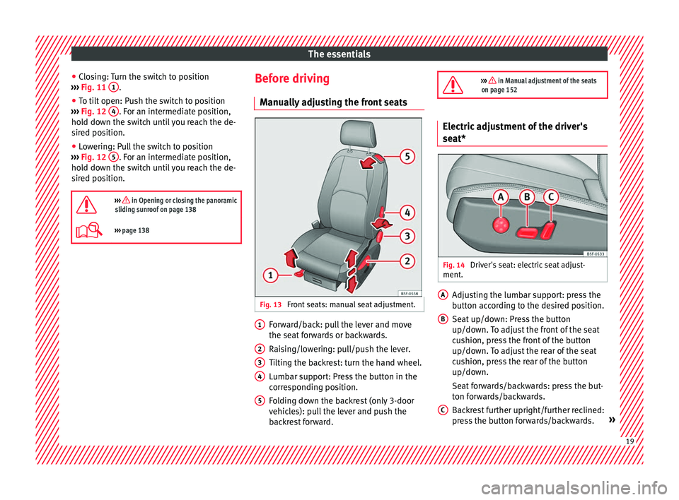
Front seats: manual seat adjustment. Forward/back: pull the lever and move
the se
at
f
orwards or backwards.
Raising/lowering: pull/push the lever.
Tilting the backrest: turn the hand wheel.
Lumbar support: Press the button in the
corresponding position.
Folding down the backrest (only 3-door
vehicles): pull the lever and push the
backrest forward.
1 2
3
4
5
››› in Manual adjustment of the seats
on page 152 Electric adjustment of the driver's
seat*
Fig. 14
Driver's seat: electric seat adjust-
ment . Adjusting the lumbar support: press the
b
utt
on ac
cording to the desired position.
Seat up/down: Press the button
up/down. To adjust the front of the seat
cushion, press the front of the button
up/down. To adjust the rear of the seat
cushion, press the rear of the button
up/down.
Seat forwards/backwards: press the but-
ton forwards/backwards.
Backrest further upright/further reclined:
press the button forwards/backwards. »
A B
C
19
Page 22 of 332
The essentials
››› in Electric driver's seat adjustment*
on page 153 Adjusting the head restraints
Fig. 15
Front seat: adjustment of the head re-
s tr
aint
. ●
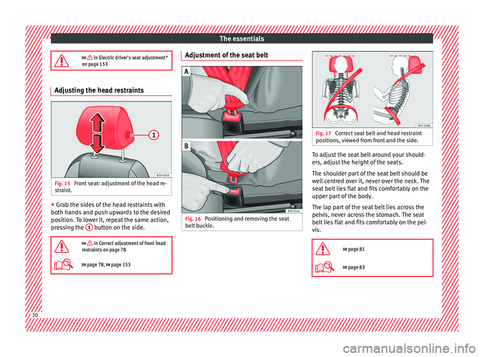
Grab the sides of the head restraints with
both h and
s
and push upwards to the desired
position. To lower it, repeat the same action,
pressing the 1 button on the side.
››› in Correct adjustment of front head
restraints on page 78
››› page 78, ››› page 153 Adjustment of the seat belt
Fig. 16
Positioning and removing the seat
belt b
uc
kle. Fig. 17
Correct seat belt and head restraint
pos ition
s, viewed from front and the side. To adjust the seat belt around your should-
er
s, a
dju
st the height of the seats.
The shoulder part of the seat belt should be
well centred over it, never over the neck. The
seat belt lies flat and fits comfortably on the
upper part of the body.
The lap part of the seat belt lies across the
pelvis, never across the stomach. The seat
belt lies flat and fits comfortably on the pel-
vis.
››› page 81
››› page 83 20
Page 23 of 332
The essentials
Seat belt tensioners During a collision, the seat belts on the front
seats
ar
e retracted automatically.
The tensioner can be triggered only once.
››› in Maintenance and disposal of belt
tensioners on page 85
››› page 84 Adjusting the exterior mirrors
Fig. 18
Detail of the driver door: control for
the e xt
erior mirr
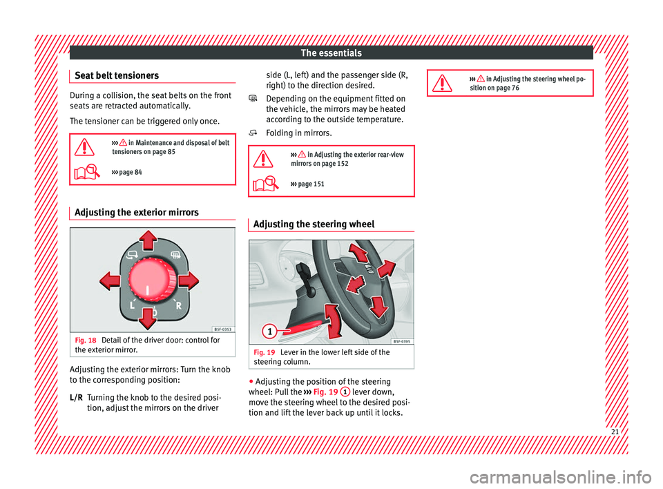
or. Adjusting the exterior mirrors: Turn the knob
t
o the c
orr
esponding position:
Turning the knob to the desired posi-
tion, adjust the mirrors on the driver
L/R side (L, left) and the passenger side (R,
right) to the direction de
sired.
Depending on the equipment fitted on
the vehicle, the mirrors may be heated
according to the outside temperature.
Folding in mirrors.
››› in Adjusting the exterior rear-view
mirrors on page 152
››› page 151 Adjusting the steering wheel
Fig. 19
Lever in the lower left side of the
s t
eerin
g column. ●
Adjusting the position of the steering
wheel: P u
l
l the ››› Fig. 19 1 lever down,
mo v
e the s
teering wheel to the desired posi-
tion and lift the lever back up until it locks.
››› in Adjusting the steering wheel po-
sition on page 76 21
Page 24 of 332
The essentials
Airbags Fr ont
airb
agsFig. 20
Driver airbag located in steering
wheel . Fig. 21
Front passenger airbag located in
d ash p
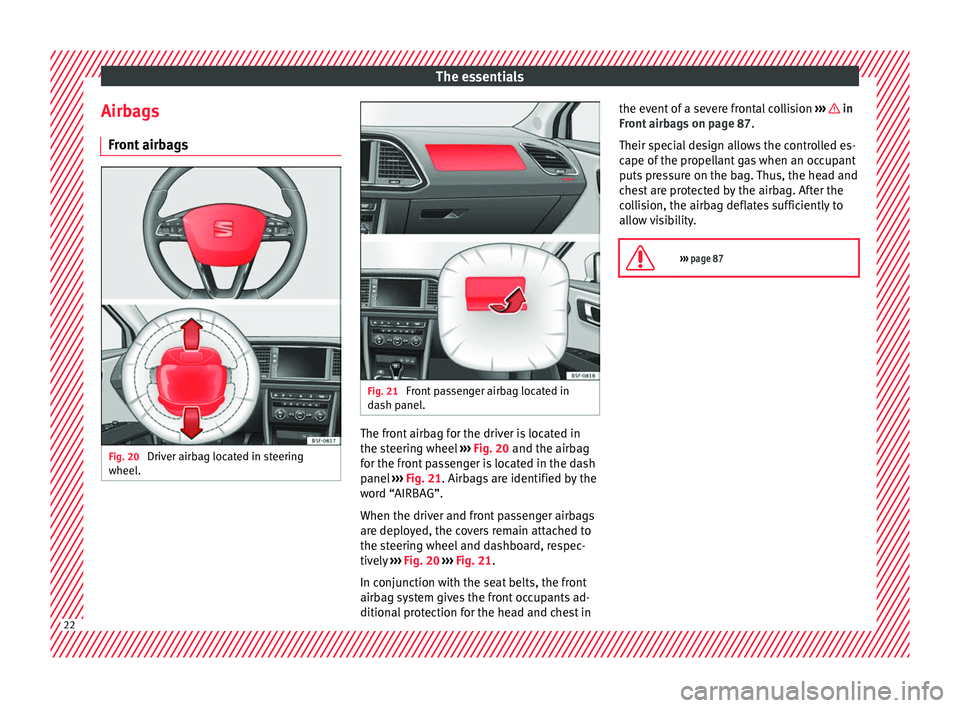
anel. The front airbag for the driver is located in
the s
t
eerin
g wheel ››› Fig. 20 and the airbag
for the front passenger is located in the dash
panel ››› Fig. 21. Airbags are identified by the
word “AIRBAG”.
When the driver and front passenger airbags
are deployed, the covers remain attached to
the steering wheel and dashboard, respec-
tively ››› Fig. 20 ››› Fig. 21.
In conjunction with the seat belts, the front
airbag system gives the front occupants ad-
ditional protection for the head and chest in the event of a severe frontal collision
›››
in
Fr ont
airb
ags on page 87.
Their special design allows the controlled es-
cape of the propellant gas when an occupant
puts pressure on the bag. Thus, the head and
chest are protected by the airbag. After the
collision, the airbag deflates sufficiently to
allow visibility.
››› page 87 22
Page 25 of 332

The essentials
Deactivating the front passenger front
airb ag Fig. 22
Front passenger front airbag switch. Fig. 23
Dash panel: control lamp for deactiva-
t ed fr
ont
passenger airbag in centre console. To deactivate the front passenger front air-
b
ag:
● Sw it
ch the ignition off.
● Open the glove compartment on the front
pas
senger side. ●
Insert
the key into the slot of the switch for
deactivating the front passenger airbag
››› Fig. 22. About 3/4 of the key should enter;
this is as far as it will go.
● Turn the key gently to the position. If
y
ou have difficulty, ensure that you have in-
serted the key as far as it will go.
● Check, with the ignition switched on, that
the contro
l lamp remains lit where it
says in the centre of the
dash panel ››› Fig. 23.
››› in Activation and deactivation of
front passenger airbag* on page 89
››› page 89 Knee airbag*
Fig. 24
On the driver side: location of the
knee airb ag Fig. 25
On the driver side: radius of action of
the knee airbag. The knee airbag is located on the driver side
belo
w the d
a
sh panel ››› Fig. 24. Airbags are
identified by the word “AIRBAG”.
The area framed in red (deployment area)
››› Fig. 25 is covered by the knee airbag when
it is deployed. Objects should never be
placed or mounted in this area.
››› page 87 23
Page 26 of 332
The essentials
Side airbags* Fig. 26
Side airbag in driver's seat. Fig. 27
Illustration of completely inflated side
airb ag
s
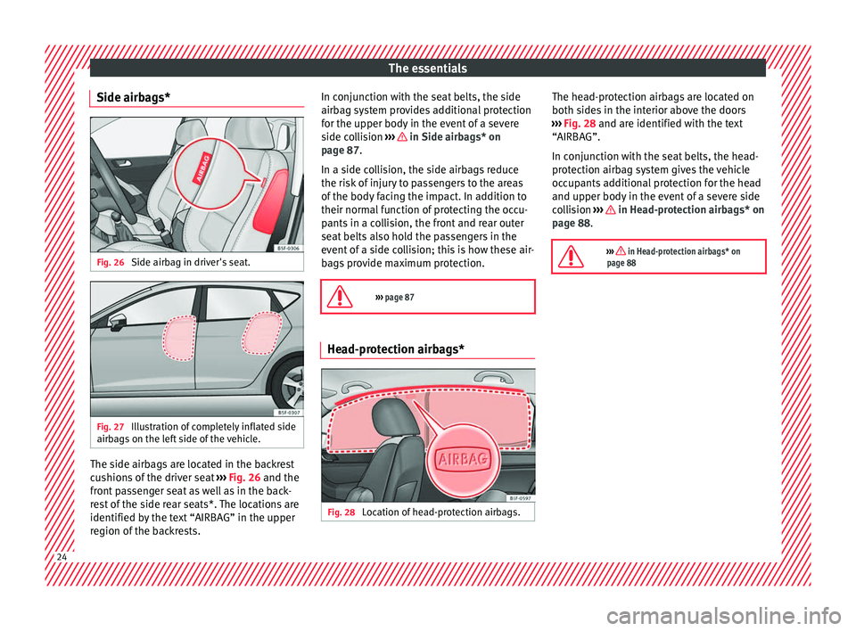
on the left side of the vehicle. The side airbags are located in the backrest
c
u
shion
s of the driver seat ››› Fig. 26 and the
front passenger seat as well as in the back-
rest of the side rear seats*. The locations are
identified by the text “AIRBAG” in the upper
region of the backrests. In conjunction with the seat belts, the side
airbag sys
tem provides additional protection
for the upper body in the event of a severe
side collision ››› in Side airbags* on
p ag
e 87
.
In a side collision, the side airbags reduce
the risk of injury to passengers to the areas
of the body facing the impact. In addition to
their normal function of protecting the occu-
pants in a collision, the front and rear outer
seat belts also hold the passengers in the
event of a side collision; this is how these air-
bags provide maximum protection.
››› page 87 Head-protection airbags*
Fig. 28
Location of head-protection airbags. The head-protection airbags are located on
both s
ide
s
in the interior above the doors
››› Fig. 28 and are identified with the text
“AIRBAG”.
In conjunction with the seat belts, the head-
protection airbag system gives the vehicle
occupants additional protection for the head
and upper body in the event of a severe side
collision ››› in Head-protection airbags* on
p ag
e 88
.
››› in Head-protection airbags* on
page 88 24
Page 27 of 332
The essentials
Child seats Impor t
ant
information regarding the
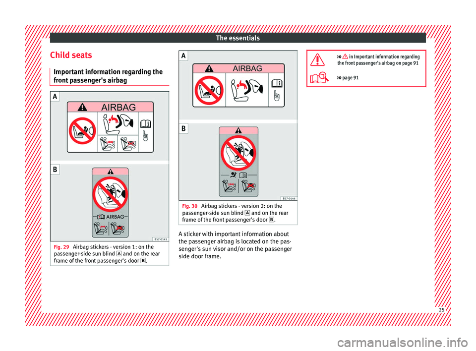
front passenger's airbag Fig. 29
Airbag stickers - version 1: on the
p a
s
senger-side sun blind and on the rear
frame of the front passenger's door . Fig. 30
Airbag stickers - version 2: on the
p a
s
senger-side sun blind and on the rear
frame of the front passenger's door . A sticker with important information about
the p
a
s
senger airbag is located on the pas-
senger's sun visor and/or on the passenger
side door frame.
››› in Important information regarding
the front passenger's airbag on page 91
››› page 91 25
Page 28 of 332
The essentials
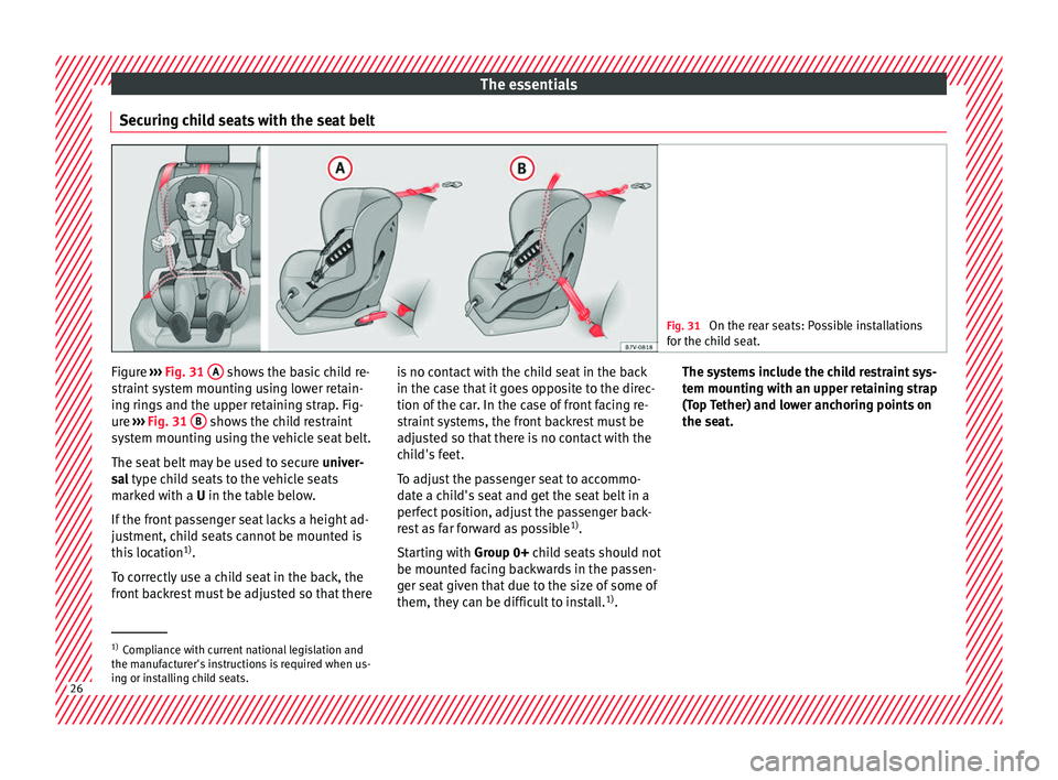
Securing child seats with the seat belt Fig. 31
On the rear seats: Possible installations
for the c hi
ld seat. Figure
›››
Fig. 31
A shows the basic child re-
s tr
aint
system mounting using lower retain-
ing rings and the upper retaining strap. Fig-
ure ››› Fig. 31 B shows the child restraint
sy s
t
em mounting using the vehicle seat belt.
The seat belt may be used to secure univer-
sal type child seats to the vehicle seats
marked with a U in the table below.
If the front passenger seat lacks a height ad-
justment, child seats cannot be mounted is
this location 1)
.
To correctly use a child seat in the back, the
front backrest must be adjusted so that there is no contact with the child seat in the back
in the case th
at it goes opposite to the direc-
tion of the car. In the case of front facing re-
straint systems, the front backrest must be
adjusted so that there is no contact with the
child's feet.
To adjust the passenger seat to accommo-
date a child's seat and get the seat belt in a
perfect position, adjust the passenger back-
rest as far forward as possible 1)
.
Starting with Group 0+ child seats should not
be mounted facing backwards in the passen-
ger seat given that due to the size of some of
them, they can be difficult to install. 1)
. The systems include the child restraint sys-
tem mountin
g with an upper retaining strap
(Top Tether) and lower anchoring points on
the seat. 1)
Compliance with current national legislation and
the manuf act
urer's instructions is required when us-
ing or installing child seats. 26
Page 29 of 332
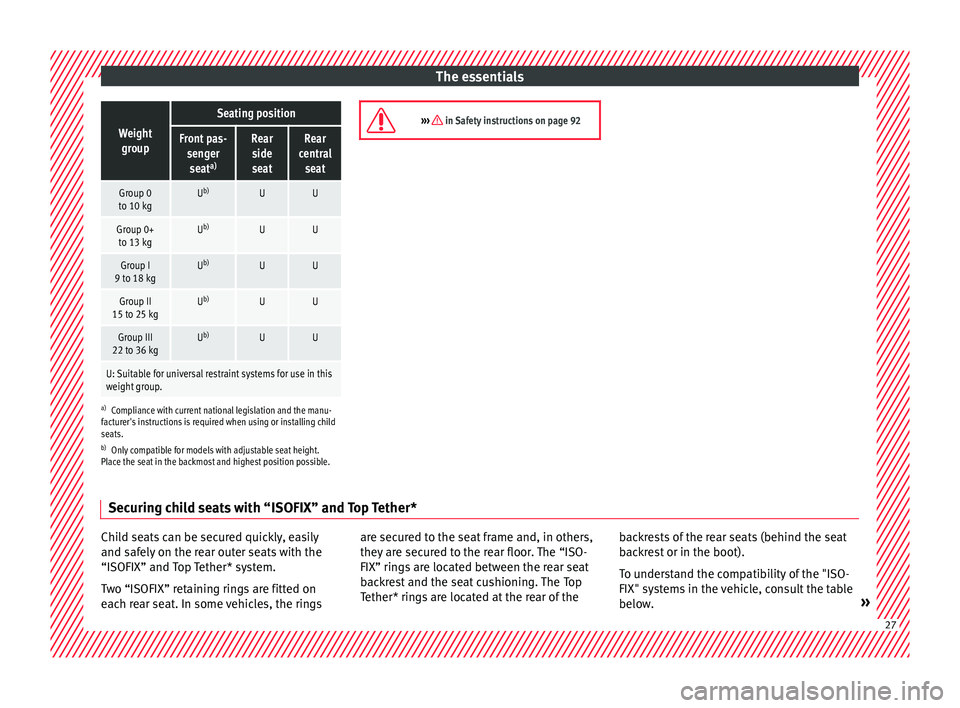
The essentialsWeight
group
Seating position
Front pas- sengerseat a)Rear
side
seatRear
central seat
Group 0
to 10 kgU b)UU
Group 0+
to 13 kgU b)UU
Group I
9 to 18 kgU b)UU
Group II
15 to 25 kgU b)UU
Group III
22 to 36 kgU b)UU
U: Suitable for universal restraint systems for use in this
weight group.
a)
Compliance with current national legislation and the manu-
facturer's instructions is required when using or installing child
seats.
b) Only compatible for models with adjustable seat height.
Place the seat in the backmost and highest position possible.
››› in Safety instructions on page 92 Securing child seats with “ISOFIX” and Top Tether*
Child seats can be secured quickly, easily
and s
af
ely
on the rear outer seats with the
“ISOFIX” and Top Tether* system.
Two “ISOFIX” retaining rings are fitted on
each rear seat. In some vehicles, the rings are secured to the seat frame and, in others,
they are sec
ured to the rear floor. The “ISO-
FIX” rings are located between the rear seat
backrest and the seat cushioning. The Top
Tether* rings are located at the rear of the backrests of the rear seats (behind the seat
back
rest or in the boot).
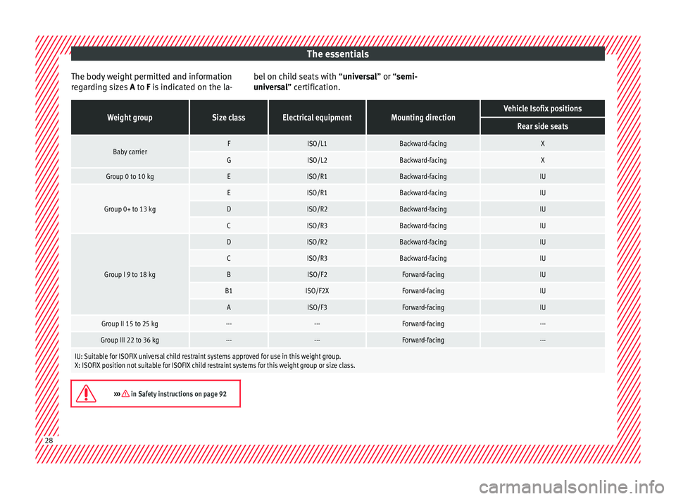
To understand the compatibility of the "ISO-
FIX" systems in the vehicle, consult the table
below. » 27
Page 30 of 332
The essentials
The body weight permitted and information
r e
g
arding sizes A to F is indicated on the la- bel on child seats with “
univer sal” or “semi-
universal” certification.
Weight groupSize classElectrical equipmentMounting directionVehicle Isofix positions
Rear side seats
Baby carrierFISO/L1Backward-facingX
GISO/L2Backward-facingX
Group 0 to 10 kgEISO/R1Backward-facingIU
Group 0+ to 13 kg
EISO/R1Backward-facingIU
DISO/R2Backward-facingIU
CISO/R3Backward-facingIU
Group I 9 to 18 kg
DISO/R2Backward-facingIU
CISO/R3Backward-facingIU
BISO/F2Forward-facingIU
B1ISO/F2XForward-facingIU
AISO/F3Forward-facingIU
Group II 15 to 25 kg------Forward-facing---
Group III 22 to 36 kg------Forward-facing---
IU: Suitable for ISOFIX universal child restraint systems approved for use in this weight group.
X: ISOFIX position not suitable for ISOFIX child restraint systems for this weight group or size class.
››› in Safety instructions on page 92
28