ABS Seat Leon SC 2017 Owner's manual
[x] Cancel search | Manufacturer: SEAT, Model Year: 2017, Model line: Leon SC, Model: Seat Leon SC 2017Pages: 332, PDF Size: 7.25 MB
Page 50 of 332
The essentials
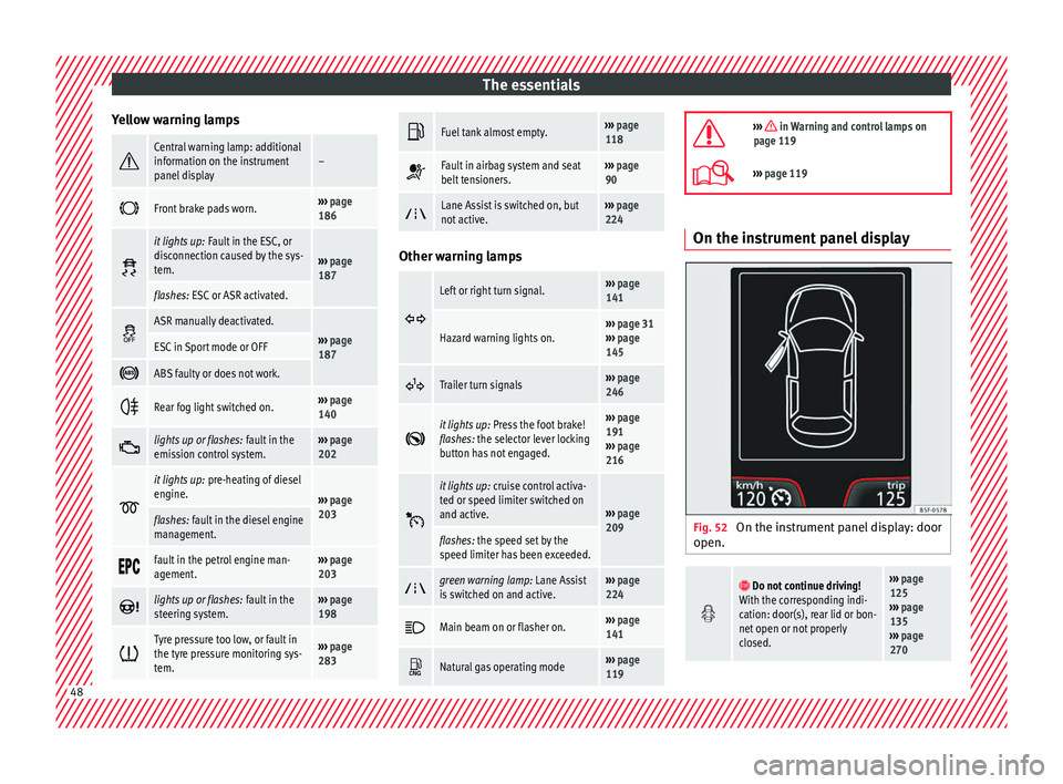
Yellow warning lamps Central warning lamp: additional
information on the instrument
panel display–
Front brake pads worn.›››
page
186
it lights up:
Fault in the ESC, or
disconnection caused by the sys-
tem.
››› page
187
flashes: ESC or ASR activated.
ASR manually deactivated.›››
page
187ESC in Sport mode or OFF
ABS faulty or does not work.
Rear fog light switched on.›››
page
140
lights up or flashes:
fault in the
emission control system.››› page
202
it lights up:
pre-heating of diesel
engine.
››› page
203
flashes: fault in the diesel engine
management.
fault in the petrol engine man-
agement.›››
page
203
lights up or flashes:
fault in the
steering system.››› page
198
Tyre pressure too low, or fault in
the tyre pressure monitoring sys-
tem.›››
page
283
Fuel tank almost empty.›››
page
118
Fault in airbag system and seat
belt tensioners.›››
page
90
Lane Assist is switched on, but
not active.›››
page
224 Other warning lamps
Left or right turn signal.›››
page
141
Hazard warning lights on.››› page 31
››› page
145
Trailer turn signals›››
page
246
it lights up:
Press the foot brake!
flashes: the selector lever locking
button has not engaged.››› page
191
››› page
216
it lights up:
cruise control activa-
ted or speed limiter switched on
and active.
››› page
209
flashes: the speed set by the
speed limiter has been exceeded.
green warning lamp: Lane Assist
is switched on and active.›››
page
224
Main beam on or flasher on.›››
page
141
Natural gas operating mode›››
page
119
››› in Warning and control lamps on
page 119
››› page 119 On the instrument panel display
Fig. 52
On the instrument panel display: door
open.
Do not continue driving!
With the corresponding indi-
cation: door(s), rear lid or bon-
net open or not properly
closed.››› page
125
››› page
135
››› page
270 48
Page 65 of 332

The essentials
Emergencies F u
se
s
Fuse location Fig. 66
On the driver-side dash panel: fuse
bo x
c
over. Fig. 67
In the engine compartment: fuse box
c o
v
er. Underneath the instrument panel
The f
use bo
x is located behind the storage
compartment ››› Fig. 66.
In the engine compartment
Press the locking tabs to release the fuse box
cover ››› Fig. 67.
Identifying fuses situated below the dash
panel by colours
ColourAmp rating
Black1
Purple3
Light brown5
Brown7.5
Red10
Blue15
Yellow20
White or transparent25
Green30
Orange40
››› in Introduction on page 101
›››
page 101 Replacing a blown fuse
Fig. 68
Image of a blown fuse. Preparation
●
Switch off the ignition, lights and all elec-
tric al
equipment
.
● Open the corresponding fuse box
›››
page 102.
Identifying a blown fuse
A fuse is blown if its metal strip is ruptured
››› Fig. 68.
● Point a lamp at the fuse to see if it has
blown.
T
o replace a fuse
● Remove the fuse.
● Replace the blown fuse by one with an
identica
l amperage rating (same colour and
markings) and identical size. » 63
Page 70 of 332

The essentials
● Find the s up
por
t point on the strut (sunken
area) closest to the wheel to be changed
››› Fig. 75.
● Turn the jack*, located below the strut sup-
port point, t
o raise it until tab 1
› ››
Fig. 76
is
below the housing provided.
● Align the jack* so that tab 1 “grips” onto
the hou s
in
g provided on the strut and the
mobile base 2 is resting on the ground. The
b a
se p
late 2 should fall vertically with re-
s pect
t
o the support point 1 .
● Continue turning the jack* until the wheel
i s
s
lightly lifted off the ground. WARNING
● Mak e s
ure that the jack* remains stable. If
the surface is slippery or soft, the jack* could
slip or sink, respectively, with the resultant
risk of injury.
● Only raise the vehicle with the jack* sup-
plied by
the manufacturer. Other vehicles
could slip, with the consequent risk of injury.
● Only mount the jack* on the support points
designed f
or this purpose on the strut, and
always align the jack correctly. If you do not,
the jack* could slip as it does not have an ad-
equate grip on the vehicle: risk of injury!
● The height of the parked vehicle can
chan
ge as a result of variations in tempera-
ture and loading. CAUTION
The vehicle must not be raised on the cross-
bar . On
ly place the jack* on the points de-
signed for this purpose on the strut. Other-
wise, the vehicle may be damaged. Removing and fitting a wheel
Change the wheel after loosening the wheel
bolts
and r
aising the vehicle with the jack.
Taking off the wheel ● Unscrew the wheel bolts using the box
sp anner and p
lace them on a clean surface.
● Take off the wheel.
Putting on the s
pare wheel
When fitting tyres with a compulsory rotation
direction, observe the instructions in
››› page 68.
● Mount the wheel.
● Screw on the wheel bolts in position and
tighten them loosely
with a box spanner.
● Carefully lower the vehicle using the jack*.
● Tighten the wheel bolts in diagonal pairs
usin
g the wheel brace.
The wheel bolts should be clean and turn
easily. Before fitting the spare wheel, inspect
the wheel condition and hub mounting surfa- ces. These surfaces must be clean before fit-
ting the wheel.
T
yres with compulsory direction of ro-
tation A directional tread pattern can be identified
by
the arr
ows on the sidewall that point in
the direction of rotation. Always observe the
direction of rotation indicated when fitting
the wheel to guarantee optimum properties
of this type of tyres with regard to grip,
noises, wear and aquaplaning.
If it is absolutely necessary to fit the spare
tyre* against the direction of rotation, drive
with care as this means the tyre does not of-
fer optimum driving properties. This is of par-
ticular importance when the road surface is
wet.
To return to directional tread tires, replace
the punctured tyre as soon as possible and
restore the obligatory direction of rotation of
all tyres.
Subsequent work ●
Alloy wheels: rep
l
ace the wheel bolt caps.
● Plate wheels: rep l
ace the wheel hubcap
››› page 66.68
Page 83 of 332

Seat belts
The protective function of seat belts Fig. 90
Drivers with properly worn seat belts
w i
l
l not be thrown forward in the event of sud-
den braking. Properly worn seat belts hold the occupants
in the pr
oper po
s
ition. They also help prevent
uncontrolled movements that may result in
serious injury and reduce the risk of being
thrown out of the vehicle in case of an acci-
dent.
Vehicle occupants wearing their seat belts
correctly benefit greatly from the ability of the
belts to absorb kinetic energy. In addition,
the front part of your vehicle and other pas-
sive safety features (such as the airbag sys-
tem) are designed to absorb the kinetic ener-
gy released in a collision. Taken together, all
these features reduce the releasing kinetic
energy and consequently, the risk of injury.
This is why it is so important to fasten seat
belts before every trip, even when "just driv-
ing around the corner". Ensure that your passengers wear their seat
belts as
well. Accident statistics have shown
that wearing seat belts is an effective means
of substantially reducing the risk of injury
and improving the chances of survival when
involved in a serious accident. Furthermore,
properly worn seat belts improve the protec-
tion provided by airbags in the event of an
accident. For this reason, wearing a seat belt
is required by law in most countries.
Although your vehicle is equipped with air-
bags, the seat belts must be fastened and
worn. The front airbags, for example, are only
triggered in some cases of head-on collision.
The front airbags will not be triggered during
minor frontal or side collisions, rear-end colli-
sions, rollovers or accidents in which the air-
bag trigger threshold value in the control unit
is not exceeded.
Therefore, you should always wear your seat
belt and ensure that all vehicle occupants
have fastened their seat belts properly before
you drive off!
Important safety instructions for the
use of se
at belts –
Always wear the seat belt as described in
thi s
section.
– En
sure that the seat belts can be fastened
at all
times and are not damaged. WARNING
● If se at
belts are worn incorrectly or not at
all, the risk of severe injuries increases. The
optimal protection from seat belts can be
achieved only if you use them properly.
● Fasten your seat belt before every trip -
even when drivin
g in town. Other vehicle oc-
cupants must also wear the seat belts at all
times, otherwise they run the risk of being in-
jured.
● The seat belt cannot offer its full protection
if the seat
belt is not positioned correctly.
● Never allow two passengers (even children)
to shar
e the same seat belt.
● Always keep both feet in the footwell in
front of
your seat as long as the vehicle is in
motion.
● Never unbuckle a seat belt while the vehi-
cle i
s in motion. Risk of fatal injury.
● The seat belt must never be twisted while it
is bein
g worn.
● The seat belt should never lie on hard or
fragil
e objects (such as glasses or pens, etc.)
because this can cause injuries.
● Do not allow the seat belt to be damaged or
jammed, or to rub on an
y sharp edges.
● Never wear the seat belt under the arm or
in any other inc
orrect position.
● Bulky and unfastened clothing (such as an
over
coat over a sweater) impairs the proper
fit and function of the seat belts, reducing
their capacity to protect. » 81
Technical data
Advice
Operation
Emergencies
Safety
Page 84 of 332
Safety
●
The slot in the se
at belt buckle must not be
blocked with paper or other objects, as this
can prevent the latch plate from engaging se-
curely.
● Never use seat belt clips, fastening rings or
simil
ar items to alter the position of the belt
webbing.
● Frayed or torn seat belts or damage to the
connections, belt
retractors or parts of the
buckle could cause severe injuries in the
event of an accident. Therefore, you must
check the condition of all seat belts at regular
intervals.
● Seat belts which have been worn in an acci-
dent and hav
e been stretched must be re-
placed by a specialised workshop. Renewal
may be necessary even if there is no apparent
damage. The belt anchorage should also be
checked.
● Do not attempt to repair a damaged seat
belt y
ourself. The seat belts must not be re-
moved or modified in any way.
● The belts must be kept clean, otherwise the
retract
ors may not work properly. Head-on collisions and the laws of
ph
y
s
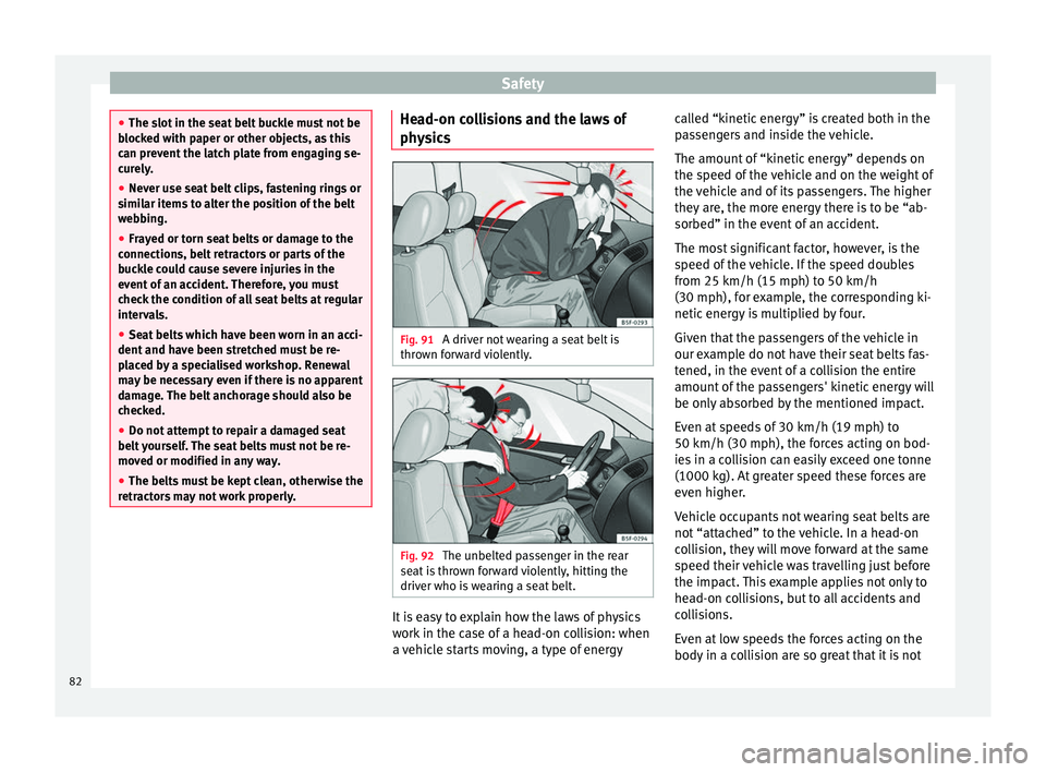
ics Fig. 91
A driver not wearing a seat belt is
thr o
wn f
orward violently. Fig. 92
The unbelted passenger in the rear
se at
i
s thrown forward violently, hitting the
driver who is wearing a seat belt. It is easy to explain how the laws of physics
w
ork
in the c
ase of a head-on collision: when
a vehicle starts moving, a type of energy called “kinetic energy” is created both in the
pas
sengers and inside the vehicle.
The amount of “kinetic energy” depends on
the speed of the vehicle and on the weight of
the vehicle and of its passengers. The higher
they are, the more energy there is to be “ab-
sorbed” in the event of an accident.
The most significant factor, however, is the
speed of the vehicle. If the speed doubles
from 25 km/h (15 mph) to 50 km/h
(30 mph), for example, the corresponding ki-
netic energy is multiplied by four.
Given that the passengers of the vehicle in
our example do not have their seat belts fas-
tened, in the event of a collision the entire
amount of the passengers' kinetic energy will
be only absorbed by the mentioned impact.
Even at speeds of 30 km/h (19 mph) to
50 km/h (30 mph), the forces acting on bod-
ies in a collision can easily exceed one tonne
(1000 kg). At greater speed these forces are
even higher.
Vehicle occupants not wearing seat belts are
not “attached” to the vehicle. In a head-on
collision, they will move forward at the same
speed their vehicle was travelling just before
the impact. This example applies not only to
head-on collisions, but to all accidents and
collisions.
Even at low speeds the forces acting on the
body in a collision are so great that it is not
82
Page 97 of 332
Self-help
Emergencies
Self -help
V ehic
le tool kit, anti-puncture kit* The tools and anti-puncture kit* are stored
under the floor p
anel
in the luggage compart-
ment.
To access the vehicle tools:
– Lift up the floor surface by the plastic han-
dle u nti
l it is fastened to the tabs on both
sides.
Depending on the vehicle equipment, the an-
ti-puncture kit* is located under the floor
panel in the luggage compartment.
The tool kit includes:
● Jack*
● Wire hook for pulling off the wheel cov-
er*/wheel bolt
cap clip.
● Box spanner for wheel bolts*
● Towline anchorage
● Adapter for the anti-theft wheel bolts*
● Towing bracket device
Some of the items
listed are only provided in
certain model versions, or are optional ex-
tras. Note
The jack does not generally require any main-
ten anc
e. If required, it should be greased us-
ing universal type grease. Tyre repair
TMS (T
yre Mobility System)* Read the additional information carefully
›› ›
page 65
The Anti-puncture kit* (Tyre Mobility System)
will reliably seal punctures caused by the
penetration of a foreign body of up to about
4 mm in diameter. Do not remove foreign ob-
jects, e.g. screws or nails, from the tyre.
After inserting the sealant residue in the tyre,
you must again check the tyre pressure about
10 minutes after starting the engine.
You should only use the tyre mobility set if
the vehicle is parked in a safe place, you are
familiar with the procedure and you have the
necessary tyre mobility set! Otherwise, you
should seek professional assistance.
Do not use the tyre sealant in the following
cases:
● If the wheel rim has been damaged.
● In outside temperatures below -20°C (-4°F). ●
In the ev ent
of
cuts or perforations in the
tyre greater than 4 mm.
● If you have been driving with very low pres-
sure or a c
ompletely flat tyre.
● If the sealant bottle has passed its use by
date. WARNING
Using the tyre mobility system can be dan-
ger ou
s, especially when filling the tyre at the
roadside. Please observe the following rules
to minimise the risk of injury:
● Stop the vehicle safely as soon as possible.
Park it
at a safe distance from surrounding
traffic to fill the tyre.
● Ensure the ground on which you park is flat
and solid.
● Al
l passengers and particularly children
must
keep a safe distance from the work area.
● Turn on the hazard warning lights to warn
other roa
d users.
● Use the tyre mobility system only if you are
famili
ar with the necessary procedures. Oth-
erwise, you should seek professional assis-
tance.
● The tyre mobility set is intended for tempo-
rary
emergency use only until you can reach
the nearest specialised workshop.
● Replace the repaired tyre with the tyre mo-
bility
set as soon as possible. » 95
Technical data
Advice
Operation
Emergencies
Safety
Page 101 of 332

Self-help
●
The to w r
ope must not be twisted. Other-
wise the front tow line anchorage could be
pulled off the vehicle. Indications for tow-starting
Vehicle's should not generally be tow-star-
ted.
The jump s
tart should be used instead
››› page 70.
For technical reasons, towing the following
vehicles is not allowed:
● Vehicles with an automatic gearbox.
● If the vehicle battery is discharged, be-
cau se in
vehicles with the Keyless Access
locking and ignition system the steering re-
mains locked and the electronic parking
brake cannot be deactivated nor can the elec-
tronic lock of the steering column be re-
leased if they are activated.
● If the battery is flat, it is possible that the
engine contr
ol units may not operate correct-
ly.
However, if the vehicle must absolutely be
tow-started (in the case of manual gearbox-
es):
● Engage the 2nd or 3rd gear.
● Keep the clutch pressed down.
● Switch on the ignition and the hazard warn-
ing lights. ●
Once both v
ehicles are moving, release the
clutch.
● Once the engine starts, press the clutch
and diseng
age the gear to avoid colliding
with the towing vehicle. Note
The vehicle can only be tow-started if the
electr onic
parking brake and, if appropriate,
the electronic lock of the steering column are
deactivated. If the vehicle has no power sup-
ply or there is an electric system fault, the
engine must be tow-started to deactivate the
electronic parking brake and the electronic
lock of the steering column. Anchoring the front tow line
Fig. 98
Right side of the front bumper: tow-
line anc hor
ag
e screwed in. The front towline anchorage is only mounted
if
the
v
ehicle has to be towed. There is a cover with an opening into which
the towline anc
horage is screwed on the right
part of the front bumper.
– To open the cover, press the left side.
– Take the towline anchorage out of the vehi-
cle t
ool kit ››› page 95.
– Screw the towline anchorage into the screw
connection as
far as it will go ››› Fig. 98 and
tighten with the wheel brace.
After use, unscrew the towline anchorage
and fit the cover back on the bumper. Put the
towline anchorage back in the vehicle tool
kit. The towline anchorage should always be
kept in the vehicle.
99
Technical data
Advice
Operation
Emergencies
Safety
Page 104 of 332
Emergencies
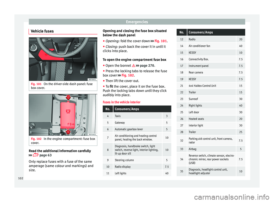
Vehicle fuses Fig. 101
On the driver-side dash panel: fuse
bo x
c
over. Fig. 102
In the engine compartment: fuse box
c o
v
er. Read the additional information carefully
› ›
›
page 63
Only replace fuses with a fuse of the same
amperage (same colour and markings) and
size. Opening and closing the fuse box situated
below the da
sh panel
● Opening: fold the cover down ››
› Fig. 101.
● Closing: push back the cover it in until it
clic
ks into place.
To open the engine compartment fuse box
● Open the bonnet ›››
page 270.
● Press the locking tabs to release the fuse
box c
over ››› Fig. 102.
● Then lift the cover out.
● To fit the cover, place it on the fuse box.
Pu
sh the locking tabs down until they click
audibly into place.
Fuses in the vehicle interior
No.Consumers/Amps
4Taxis3
5Gateway5
6Automatic gearbox lever5
7Air conditioning and heating control
panel, heating the back window.10
8Diagnosis, handbrake switch, light
switch, reverse light, interior lighting,
lit-up door sill10
9Steering column5
10Radio display7.5
11Left lights40
No.Consumers/Amps
12Radio20
14Air conditioner fan40
15KESSY10
16Connectivity Box.7.5
17Instrument panel7.5
18Rear camera7.5
19KESSY7.5
214x4 Haldex Control Unit15
22Trailer15
23Sunroof30
24Right lights40
25Left door30
26Heated seats20
27Interior light30
28Trailer25
32Parking aid control unit, front camera,
radar7.5
33Airbag5
34Reverse switch, climate sensor, electro-
chromic mirror, rear power sockets
(USB)7.5
35Diagnosis, headlight control unit,
headlight adjuster10 102
Page 110 of 332
Emergencies
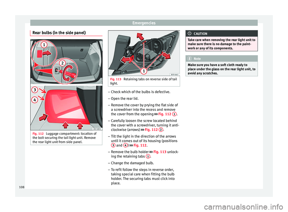
Rear bulbs (in the side panel) Fig. 112
Luggage compartment: location of
the bo lt
sec
uring the tail light unit. Remove
the rear light unit from side panel. Fig. 113
Retaining tabs on reverse side of tail
light. –
Check which of the bulbs is defective.
– Open the rear lid.
– Remove the cover by prying the flat side of
a s c
r
ewdriver into the recess and remove
the cover from the opening ››› Fig. 112 1 .
– Carefully loosen the screw located behind
the c o
v
er with a screwdriver, turning it anti-
clockwise (arrows) ››› Fig. 112 2 .
– Tilt the light in the direction of the arrows
unti
l
it comes out of its housing (positions
3 and
4 )
››
› Fig. 112
.
– Remove the bulb holder ›››
Fig. 113 unlock-
ing the retaining tabs 1 .
– Change the damaged bulb.
– To refit follow the steps in reverse order,
tak
in
g special care when fitting the bulb
holder. The securing tabs must click into
place. CAUTION
Take care when removing the rear light unit to
mak e s
ure there is no damage to the paint-
work or any of its components. Note
Make sure you have a soft cloth ready to
pl ac
e under the glass on the rear light unit, to
avoid any scratches. 108
Page 111 of 332

Fuses and bulbs
Rear light bulbs (in the rear lid) Fig. 114
Remove the cover from the boot lid
and det ac
h the b
ulb holder. Fig. 115
Position of the bulbs in the bulb
hol der The rear lid must be open to change the
b
u
l
bs.
– Remove the rear lid cover in the direction
indicated ›
›› Fig. 114 .
– Unlock the retaining tabs A of the bulb
ho l
der
, following the direction of arrows 1 and
2
› ›
› Fig. 114
.
– Remove the bulb holder, moving it in the
direction of arr
ow 3
› ›
› Fig. 114 .
– Lightly press the defective bulb into the
bul
b holder 1 , then turn it to the left
2 and remove it
››
›
Fig. 115.
– Fit the new bulb, pressing it into the bulb
holder and t
urn it to the right as far as it
will go.
– Use a cloth to remove any fingerprints from
the glas
s part of the bulb.
– Check that the new bulb works properly. –
Reins
tall the bulb holder, making sure that
locking clips A
› ››
Fig. 114
are properly
clipped on.
– Replace the cover of the rear lid lining.
Rear LED light bulb (in the rear lid) Fig. 116
Remove the cover from the rear lid Fig. 117
Remove the bulb holder. » 109
Technical data
Advice
Operation
Emergencies
Safety