Seat Leon Sportstourer 2013 Owner's manual
Manufacturer: SEAT, Model Year: 2013, Model line: Leon Sportstourer, Model: Seat Leon Sportstourer 2013Pages: 339, PDF Size: 4.8 MB
Page 301 of 339
299
Fuses and bulbs
– Remove the bulb by pressing on the bulb holder and turning it
anti-clockwise at the same time.
– Installation involves all of the above steps in reverse sequence.
– Check that the bulb works properly.
Changing tail light bulbs (on side panel) Overview of tail lights
Rear lights on the side panel
Turn signalPY21W NA LLSide light and brake lightP21W LL Removing tail light
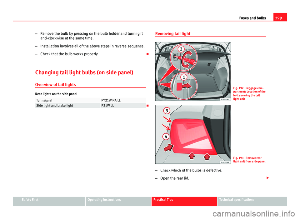
Fig. 192 Luggage com-
partment: Location of the
bolt securing the tail
light unit
Fig. 193 Remove rear
light unit from side panel
– Check which of the bulbs is defective.
– Open the rear lid.
Safety FirstOperating instructionsPractical TipsTechnical specifications
Page 302 of 339
300Fuses and bulbs
–Remove the cover by prying the flat side of a screwdriver into
the recess and remove the cover from the opening ⇒ Fig. 192
1
.
– Carefully loosen the screw located behind the cover with a
screwdriver, turning it anti-clockwise (arrows) ⇒ Fig. 192 2
.
– Tilt the light in the direction of the arrows until it comes out (po-
sitions 3
and 4 ⇒ Fig. 193).
– Remove the bulb holder ⇒ page 300.
CAUTION
Take care when removing the rear light unit to make sure there is no dam-
age to the paintwork or any of its components.
Note
Make sure you have a soft cloth ready to place under the glass on the rear
light unit, to avoid any scratches. Remove the bulb holder
When changing a bulb, you must first remove the bulb hold-
er.
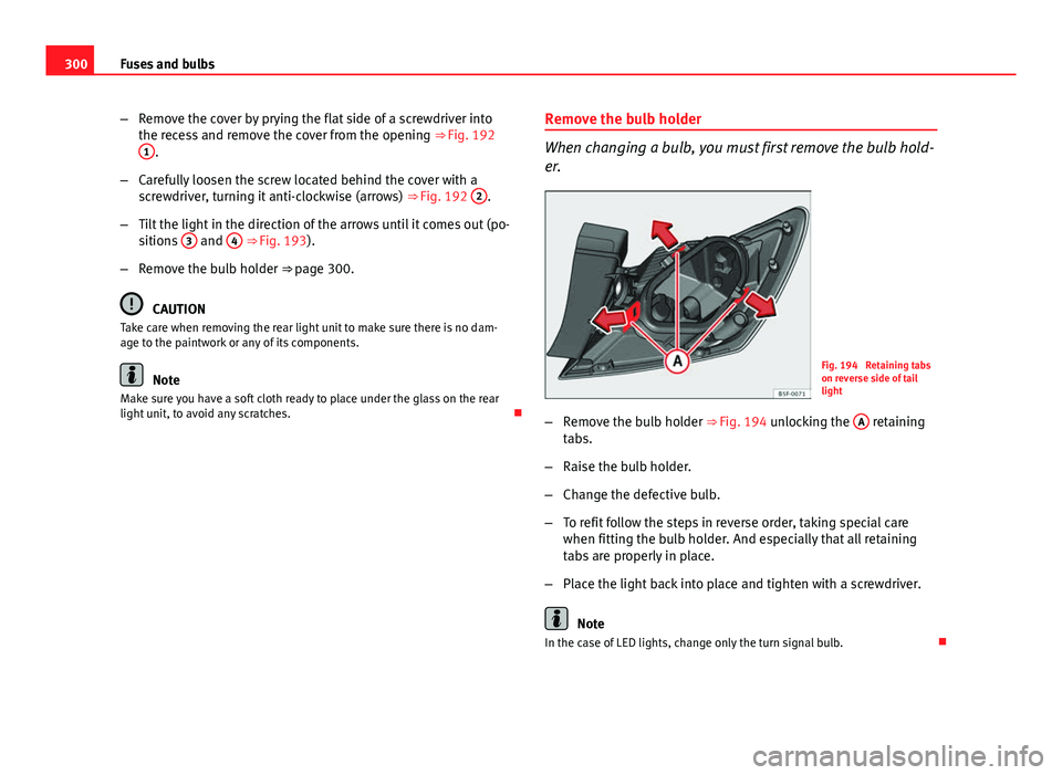
Fig. 194 Retaining tabs
on reverse side of tail
light
– Remove the bulb holder ⇒ Fig. 194 unlocking the A
retaining
tabs.
– Raise the bulb holder.
– Change the defective bulb.
– To refit follow the steps in reverse order, taking special care
when fitting the bulb holder. And especially that all retaining
tabs are properly in place.
– Place the light back into place and tighten with a screwdriver.
Note
In the case of LED lights, change only the turn signal bulb.
Page 303 of 339
301
Fuses and bulbs
Changing tail light bulbs (on rear lid)
Overview of tail lights
Rear lights on tailgate
Left sideSide lights2x W5W LLFog lightsH21 WRight sideSide lights2x W5W LLReverse lightP21W LL
The above table corresponds to a right-hand traffic vehicle. The position of
lights may vary according to the country. Remove the bulb holder
The rear lid must be open to change the bulbs.
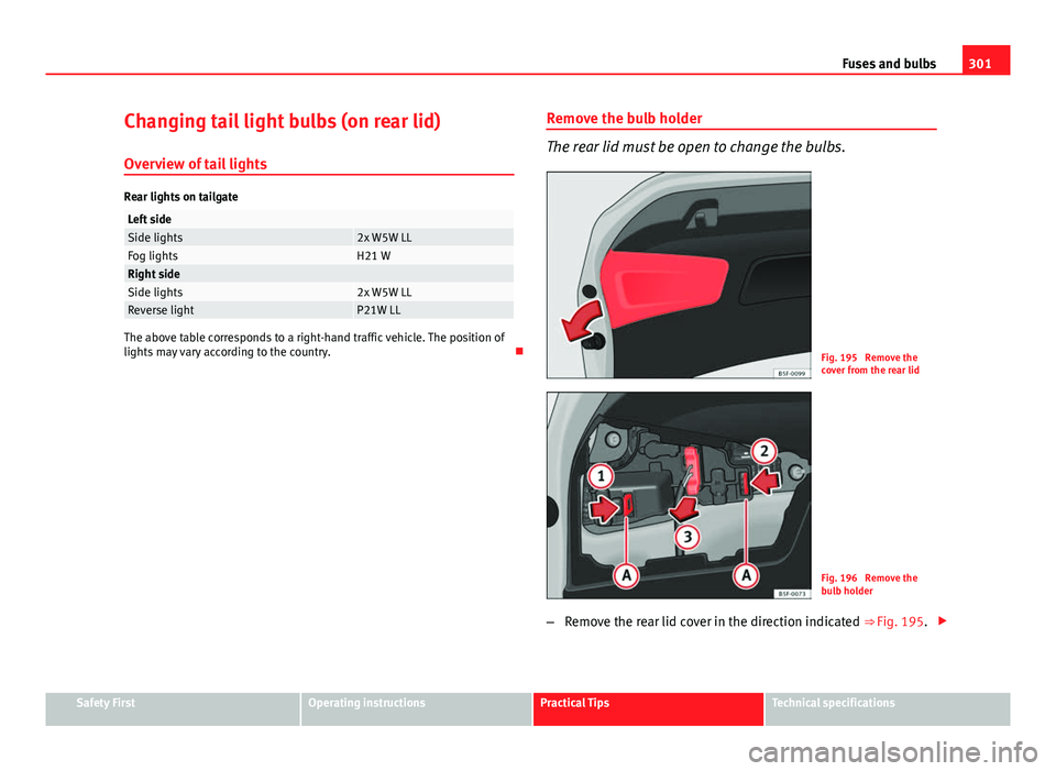
Fig. 195 Remove the
cover from the rear lid
Fig. 196 Remove the
bulb holder
– Remove the rear lid cover in the direction indicated ⇒ Fig. 195.
Safety FirstOperating instructionsPractical TipsTechnical specifications
Page 304 of 339
302Fuses and bulbs
–Unlock the retaining tabs A
of the bulb holder, following the
direction of arrows 1 and 2 ⇒ Fig. 196.
– Remove the bulb holder by turning it in the direction of arrow
3
⇒ Fig. 196.
Changing bulbs
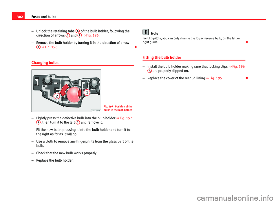
Fig. 197 Position of the
bulbs in the bulb holder
– Lightly press the defective bulb into the bulb holder ⇒ Fig. 197
1
, then turn it to the left 2 and remove it.
– Fit the new bulb, pressing it into the bulb holder and turn it to
the right as far as it will go.
– Use a cloth to remove any fingerprints from the glass part of the
bulb.
– Check that the new bulb works properly.
– Replace the bulb holder.
Note
For LED pilots, you can only change the fog or reverse bulb, on the left or
right guide.
Fitting the bulb holder
– Install the bulb holder making sure that locking clips ⇒ Fig. 196
A are properly clipped on.
– Replace the cover of the rear lid lining ⇒ Fig. 195.
Page 305 of 339
303
Fuses and bulbs
Changing number plate light bulbs.
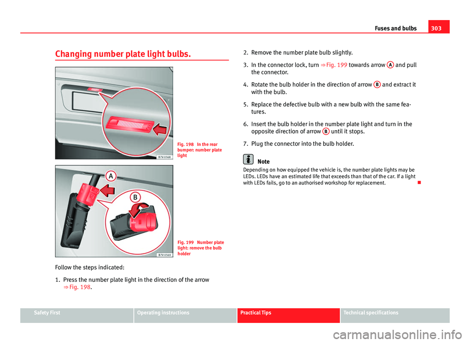
Fig. 198 In the rear
bumper: number plate
light
Fig. 199 Number plate
light: remove the bulb
holder
Follow the steps indicated:
1. Press the number plate light in the direction of the arrow ⇒ Fig. 198. 2. Remove the number plate bulb slightly.
3. In the connector lock, turn ⇒ Fig. 199 towards arrow
A
and pull
the connector.
4. Rotate the bulb holder in the direction of arrow B
and extract it
with the bulb.
5. Replace the defective bulb with a new bulb with the same fea- tures.
6. Insert the bulb holder in the number plate light and turn in the opposite direction of arrow B
until it stops.
7. Plug the connector into the bulb holder.
Note
Depending on how equipped the vehicle is, the number plate lights may be
LEDs. LEDs have an estimated life that exceeds than that of the car. If a light
with LEDs fails, go to an authorised workshop for replacement.
Safety FirstOperating instructionsPractical TipsTechnical specifications
Page 306 of 339
304Technical specifications
Technical specifications
Technical specifications
Important
The information in the vehicle documentation always takes
precedence over the information in this Instruction Manual.
All technical specifications provided in this documentation are valid for the
standard model in Spain. The vehicle data card included in the Mainte-
nance Programme or the vehicle registration documentation shows which
engine is installed in the vehicle.
The figures may be different depending whether additional equipment is fit-
ted, for different models, for special vehicles and for other countries. Abbreviations used in the Technical Specifications sectionAbbrevia-
tionMeaning
kWKilowatt, engine power measurement.
PSPferdestärke (horsepower), formerly used to denote engine
power.
rpmRevolutions per minute - engine speed.NmNewton metres, unit of engine torque.litres per100 kmFuel consumption in litres per 100 km (70 miles).
g/kmCarbon dioxide emissions in grams per km (mile) travelled.CO 2Carbon dioxideCNCetane number, indication of the diesel combustion power.
RONResearch octane number, indication of the knock resistance
of petrol.
Page 307 of 339
305
Technical specifications
Vehicle identification data
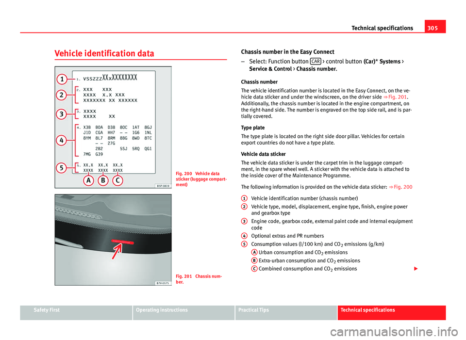
Fig. 200 Vehicle data
sticker (luggage compart-
ment)
Fig. 201 Chassis num-
ber. Chassis number in the Easy Connect
–
Select: Function button CAR
> control button
(Car)* Systems >
Service & Control > Chassis number .
Chassis number
The vehicle identification number is located in the Easy Connect, on the ve-
hicle data sticker and under the windscreen, on the driver side ⇒ Fig. 201.
Additionally, the chassis number is located in the engine compartment, on
the right-hand side. The number is engraved on the top side rail, and is par-
tially covered.
Type plate
The type plate is located on the right side door pillar. Vehicles for certain
export countries do not have a type plate.
Vehicle data sticker
The vehicle data sticker is under the carpet trim in the luggage compart-
ment, in the spare wheel well. A sticker with the vehicle data is attached to
the inside cover of the Maintenance Programme.
The following information is provided on the vehicle data sticker: ⇒ Fig. 200
Vehicle identification number (chassis number)
Vehicle type, model, displacement, engine type, finish, engine power
and gearbox type
Engine code, gearbox code, external paint code and internal equipment
code
Optional extras and PR numbers
Consumption values (l/100 km) and CO 2 emissions (g/km)
A
Urban consumption and CO 2 emissions
B Extra-urban consumption and CO 2 emissions
C Combined consumption and CO 2 emissions
1
2
3
45
Safety FirstOperating instructionsPractical TipsTechnical specifications
Page 308 of 339
306Technical specifications
Identifying letters
The identifying letters of the engine can be viewed on the instrument panel.
Important: The engine must be off and the ignition on.
● Hold down the 0.0/SET
4 ⇒ Fig. 38 button for more than 15 seconds.
Information on fuel consumption
Fuel consumption
The consumption and emission details shown on the vehicle
data sticker differ from one vehicle to another. The vehicle fuel consumption and CO 2 emissions can be consulted on the
vehicle data sticker in the spare wheel well, inside the luggage compart-
ment and on the rear cover of the Maintenance Programme.
The fuel consumption and CO 2 emission values refer to the weight category
assigned to your vehicle according to the engine and gearbox combination,
as well as the specific equipment fitted, and is only used to compare be-
tween the different models.
The fuel consumption and CO 2 emissions do not depend only on the per-
formance of the vehicle, they can also differ from the established values de-
pending on other factors such as driving style, road conditions, traffic con-
ditions, environmental conditions, load and number of passengers.
Calculation of fuel consumption
The consumption values have been calculated based on measurements per-
formed or supervised by certified CE laboratories according to the latest ver-
sion of directives 715/2007/EC and 80/1268/CEE (for more information
consult the European Union Publications Office at EUR-Lex: © European Un- ion, http://eur-lex.europa.eu/en/index.htm) and are valid for the kerb
weight indicated for the vehicle.
Note
In practice, and considering all the factors mentioned here, consumption
values can differ from those calculated in the current European regulations.
Weights
Kerb weight refers to the basic model with a fuel tank filled to 90% capacity
and without optional extras. The figure quoted includes 75 kg to allow for
the weight of the driver.
For special versions and optional equipment fittings or for the addition of
accessories, the weight of the vehicle will increase ⇒
.
WARNING
● Please note that the centre of gravity may shift when transporting
heavy objects; this may affect vehicle handling and lead to an accident.
Always adjust your speed and driving style to suit road conditions and re-
quirements.
● Never exceed the gross axle weight rating or the gross vehicle weight
rating. If the allowed axle load or the allowed total weight is exceeded,
the driving characteristics of the vehicle may change, leading to acci-
dents, injuries and damage to the vehicle.
Page 309 of 339
307
Technical specifications
Towing a trailer Trailer weights
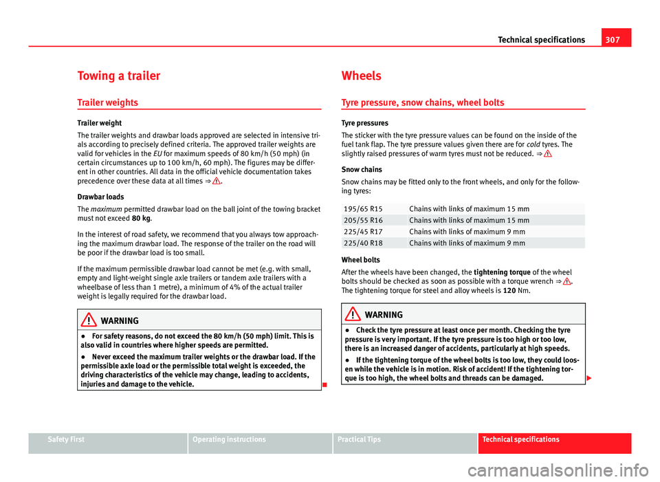
Trailer weight
The trailer weights and drawbar loads approved are selected in intensive tri-
als according to precisely defined criteria. The approved trailer weights are
valid for vehicles in the EU for maximum speeds of 80 km/h (50 mph) (in
certain circumstances up to 100 km/h, 60 mph). The figures may be differ-
ent in other countries. All data in the official vehicle documentation takes
precedence over these data at all times ⇒
.
Drawbar loads
The maximum permitted drawbar load on the ball joint of the towing bracket
must not exceed 80 kg.
In the interest of road safety, we recommend that you always tow approach-
ing the maximum drawbar load. The response of the trailer on the road will
be poor if the drawbar load is too small.
If the maximum permissible drawbar load cannot be met (e.g. with small,
empty and light-weight single axle trailers or tandem axle trailers with a
wheelbase of less than 1 metre), a minimum of 4% of the actual trailer
weight is legally required for the drawbar load.
WARNING
● For safety reasons, do not exceed the 80 km/h (50 mph) limit. This is
also valid in countries where higher speeds are permitted.
● Never exceed the maximum trailer weights or the drawbar load. If the
permissible axle load or the permissible total weight is exceeded, the
driving characteristics of the vehicle may change, leading to accidents,
injuries and damage to the vehicle.
Wheels
Tyre pressure, snow chains, wheel bolts
Tyre pressures
The sticker with the tyre pressure values can be found on the inside of the
fuel tank flap. The tyre pressure values given there are for cold tyres. The
slightly raised pressures of warm tyres must not be reduced. ⇒
Snow chains
Snow chains may be fitted only to the front wheels, and only for the follow-
ing tyres:
195/65 R15Chains with links of maximum 15 mm205/55 R16Chains with links of maximum 15 mm225/45 R17Chains with links of maximum 9 mm225/40 R18Chains with links of maximum 9 mm
Wheel bolts
After the wheels have been changed, the tightening torque of the wheel
bolts should be checked as soon as possible with a torque wrench ⇒
.
The tightening torque for steel and alloy wheels is 120 Nm.
WARNING
● Check the tyre pressure at least once per month. Checking the tyre
pressure is very important. If the tyre pressure is too high or too low,
there is an increased danger of accidents, particularly at high speeds.
● If the tightening torque of the wheel bolts is too low, they could loos-
en while the vehicle is in motion. Risk of accident! If the tightening tor-
que is too high, the wheel bolts and threads can be damaged.
Safety FirstOperating instructionsPractical TipsTechnical specifications
Page 310 of 339
308Technical specifications
Note
We recommend that you ask your Technical Service for information about
appropriate wheel, tyre and snow chain size.