service Seat Leon Sportstourer 2013 Repair Manual
[x] Cancel search | Manufacturer: SEAT, Model Year: 2013, Model line: Leon Sportstourer, Model: Seat Leon Sportstourer 2013Pages: 339, PDF Size: 4.8 MB
Page 279 of 339
277
Emergencies
Note
Do not use the compressor for longer than 6 minutes at a time, as it could
overheat. Once it has cooled down, the compressor may be used again.
After changing a wheel
– Attach the “max label. 80 km/h” from the tyre repair kit on the
instrument panel, clearly within driver's field of view.
– Stop the vehicle after 10 minutes driving and check the tyre
pressure.
– If tyre pressure is less than 1.3 bar, the tyre is too badly dam-
aged. Do not carry on driving!
WARNING
After repairing a tyre please note the following points:
● Do not drive faster than 80 km/h.
● Avoid heavy acceleration, hard braking and fast cornering.
● Vehicle handling could be impaired.
● If the tyre is very damaged, seek professional assistance.
For the sake of the environment
You can dispose of the used bottle of sealing compound at a SEAT Official
Service.
Note
After repairing a tyre, remember to purchase a new bottle of sealing com-
pound from a SEAT Official Service or a specialised workshop. Changing a wheel
What to do first
Before changing the wheel, the following preliminary steps
are required. – Please observe the important safety notes ⇒ page 274.
– Apply the handbrake.
– Manual gearbox: Select first gear.
– Automatic gearbox: Move the selector lever to P.
– When towing a trailer: Unhitch the trailer from your vehicle.
– Have the vehicle tool kit ⇒ page 274 and the spare wheel ready
⇒ page 282.
WARNING
If you change the wheel on a slope, block the wheel on the opposite side
of the car with a stone or similar to prevent the vehicle from moving.
Safety FirstOperating instructionsPractical TipsTechnical specifications
Page 281 of 339
279
Emergencies
Anti-theft wheel bolts
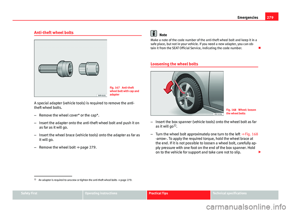
Fig. 167 Anti-theft
wheel bolt with cap and
adapter
A special adapter (vehicle tools) is required to remove the anti-
theft wheel bolts.
– Remove the wheel cover* or the cap*.
– Insert the adapter onto the anti-theft wheel bolt and push it on
as far as it will go.
– Insert the wheel brace (vehicle tools) onto the adapter as far as
it will go.
– Remove the wheel bolt ⇒ page 279.
Note
Make a note of the code number of the anti-theft wheel bolt and keep it in a
safe place, but not in your vehicle. If you need a new adapter, you can ob-
tain it from the SEAT Official Service, indicating the code number.
Loosening the wheel bolts
Fig. 168 Wheel: loosen
the wheel bolts
– Insert the box spanner (vehicle tools) onto the wheel bolt as far
as it will go 1)
.
– Turn the wheel bolt approximately one turn to the left ⇒ Fig. 168
-arrow-. To apply the required torque, hold the wheel brace at
the end. If it is not possible to loosen a wheel bolt, carefully ap-
ply pressure with one foot on the end of the box spanner. Hold
on to the vehicle for support and take care not to slip.
1)
An adapter is required to unscrew or tighten the anti-theft wheel bolts ⇒ page 279.
Safety FirstOperating instructionsPractical TipsTechnical specifications
Page 284 of 339
282Emergencies
To benefit from the advantages of tyres with this type of tread pattern, the
defective tyre should be replaced as soon as possible so that all tyres again
rotate in the correct direction.
After changing a wheel
– On alloy wheels: replace the wheel bolt caps.
– On plate wheels: replace the wheel hubcap ⇒ page 278.
– Put the tools and jack back in the luggage compartment.
– If the replaced wheel does not fit in the spare wheel housing,
store it safely in the luggage compartment ⇒ page 17.
– Check the tyre pressure of the newly mounted tyre as soon as
possible.
– In vehicles fitted with a tyre pressure indicator, adjust the pres-
sure and store the reading in the radio/Easy Connect system*
⇒ page 214.
– The wheel bolts should be tightened to 120 Nm. Check the tor-
que as soon as possible with a torque wrench. Meanwhile, drive
carefully.
– Have the flat tyre replaced as quickly as possible. Spare wheel
General information
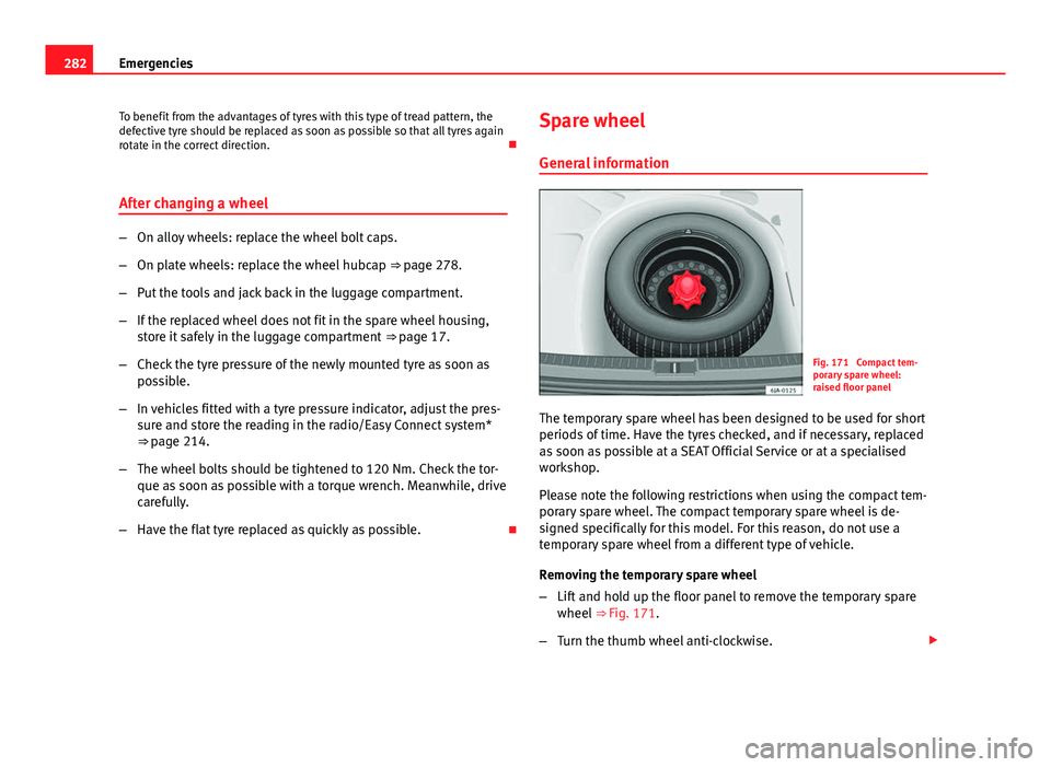
Fig. 171 Compact tem-
porary spare wheel:
raised floor panel
The temporary spare wheel has been designed to be used for short
periods of time. Have the tyres checked, and if necessary, replaced
as soon as possible at a SEAT Official Service or at a specialised
workshop.
Please note the following restrictions when using the compact tem-
porary spare wheel. The compact temporary spare wheel is de-
signed specifically for this model. For this reason, do not use a
temporary spare wheel from a different type of vehicle.
Removing the temporary spare wheel
– Lift and hold up the floor panel to remove the temporary spare
wheel ⇒ Fig. 171.
– Turn the thumb wheel anti-clockwise.
Page 293 of 339
291
Fuses and bulbs
Fuses and bulbs Fuses
Introduction
Due to the constant update of vehicles, fuse assignments depending on
equipment and the use of the same fuse for various electrical components,
at the time of printing this manual it is not possible to provide an up-to-date
summary of the electrical components fuse positions. For detailed informa-
tion about the fuse positions, please consult a Technical Service.
In general, a fuse can be assigned to various electrical components. Like-
wise, an electrical component can be protected by several fuses.
Only replace fuses when the cause of the problem has been solved. If a
newly inserted fuse blows after a short time, you must have the electrical
system checked by a specialised workshop as soon as possible.
Additional information and warnings:
● Working in the engine compartment ⇒ page 251
WARNING
The high voltages in the electrical system can give serious electrical
shocks, causing burns and even death!
● Never touch the electrical wiring of the ignition system.
● Take care not to cause short circuits in the electrical system.
WARNING
Using unsuitable fuses, repairing fuses or bridging a current circuit with-
out fuses can cause a fire and serious injury.
● Never use a fuse with a higher value. Only replace fuses with a fuse of
the same amperage (same colour and markings) and size.
● Never repair a fuse.
● Never replace a fuse by a metal strip, staple or similar.
CAUTION
● To avoid damage to the vehicles electric system, before replacing a fuse
turn off the ignition, the lights and all electrical elements and remove the
keys from the ignition.
● If you replace a fuse with higher-rating fuse, you could cause damage to
another part of the electrical system.
● Protect the fuse boxes when open to avoid the entry of dust or humidity.
Dirt and humidity inside fuse boxes can cause damage to the electrical sys-
tem.
Note
● One single consumer could have more than one fuse.
● Several consumers could run over one single fuse.
Safety FirstOperating instructionsPractical TipsTechnical specifications
Page 299 of 339
297
Fuses and bulbs
Changing bulb for front fog light
Front fog light bulb
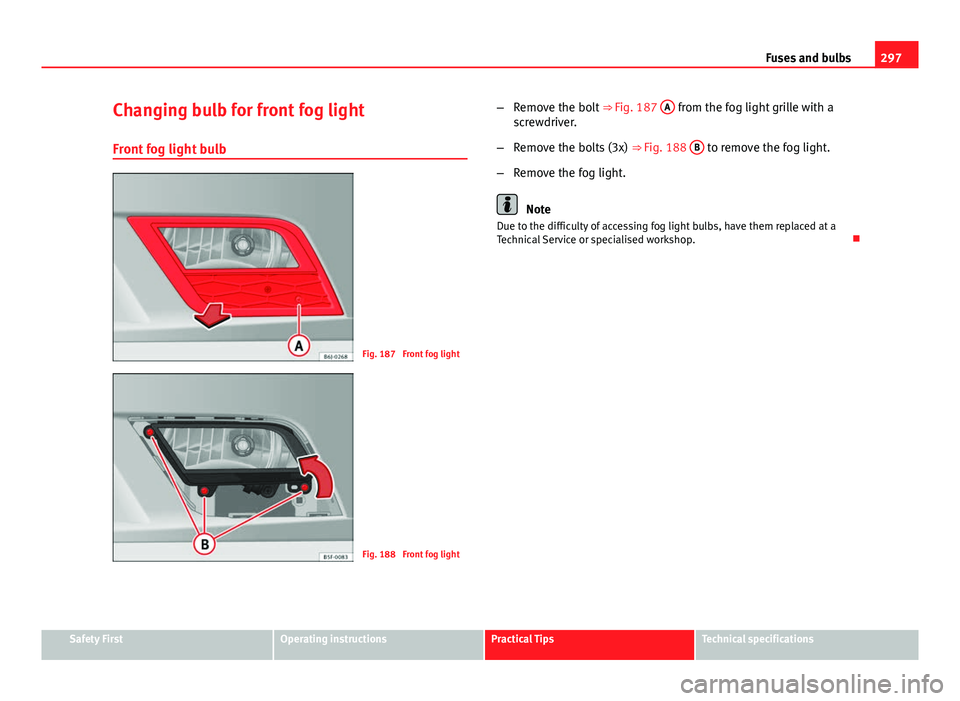
Fig. 187 Front fog light
Fig. 188 Front fog light –
Remove the bolt ⇒ Fig. 187 A
from the fog light grille with a
screwdriver.
– Remove the bolts (3x) ⇒ Fig. 188 B
to remove the fog light.
– Remove the fog light.
Note
Due to the difficulty of accessing fog light bulbs, have them replaced at a
Technical Service or specialised workshop.
Safety FirstOperating instructionsPractical TipsTechnical specifications
Page 300 of 339
298Fuses and bulbs
Fog light, FR version
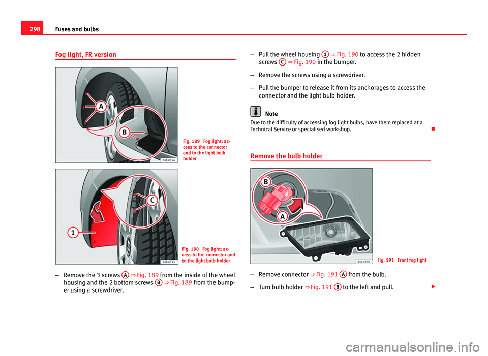
Fig. 189 Fog light: ac-
cess to the connector
and to the light bulb
holder
Fig. 190 Fog light: ac-
cess to the connector and
to the light bulb holder
– Remove the 3 screws A
⇒ Fig. 189 from the inside of the wheel
housing and the 2 bottom screws B ⇒ Fig. 189 from the bump-
er using a screwdriver. –
Pull the wheel housing 1
⇒ Fig. 190 to access the 2 hidden
screws C ⇒ Fig. 190 in the bumper.
– Remove the screws using a screwdriver.
– Pull the bumper to release it from its anchorages to access the
connector and the light bulb holder.
Note
Due to the difficulty of accessing fog light bulbs, have them replaced at a
Technical Service or specialised workshop.
Remove the bulb holder
Fig. 191 Front fog light
– Remove connector ⇒
Fig. 191 A
from the bulb.
– Turn bulb holder ⇒
Fig. 191 B
to the left and pull.
Page 307 of 339
305
Technical specifications
Vehicle identification data
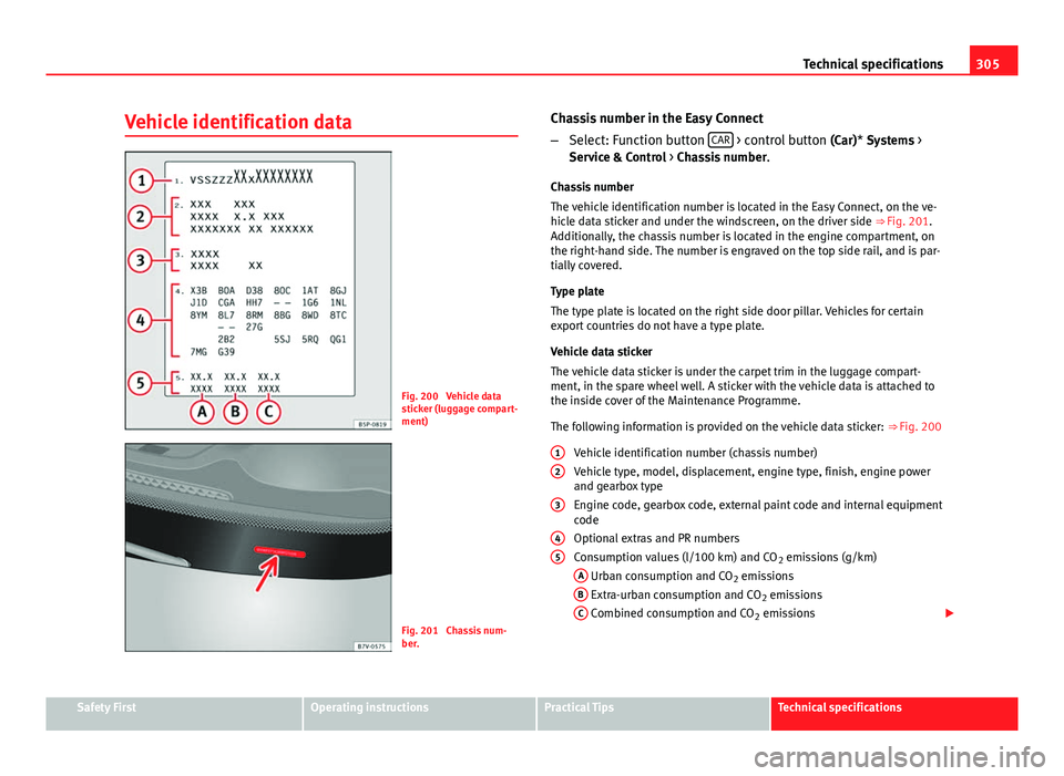
Fig. 200 Vehicle data
sticker (luggage compart-
ment)
Fig. 201 Chassis num-
ber. Chassis number in the Easy Connect
–
Select: Function button CAR
> control button
(Car)* Systems >
Service & Control > Chassis number .
Chassis number
The vehicle identification number is located in the Easy Connect, on the ve-
hicle data sticker and under the windscreen, on the driver side ⇒ Fig. 201.
Additionally, the chassis number is located in the engine compartment, on
the right-hand side. The number is engraved on the top side rail, and is par-
tially covered.
Type plate
The type plate is located on the right side door pillar. Vehicles for certain
export countries do not have a type plate.
Vehicle data sticker
The vehicle data sticker is under the carpet trim in the luggage compart-
ment, in the spare wheel well. A sticker with the vehicle data is attached to
the inside cover of the Maintenance Programme.
The following information is provided on the vehicle data sticker: ⇒ Fig. 200
Vehicle identification number (chassis number)
Vehicle type, model, displacement, engine type, finish, engine power
and gearbox type
Engine code, gearbox code, external paint code and internal equipment
code
Optional extras and PR numbers
Consumption values (l/100 km) and CO 2 emissions (g/km)
A
Urban consumption and CO 2 emissions
B Extra-urban consumption and CO 2 emissions
C Combined consumption and CO 2 emissions
1
2
3
45
Safety FirstOperating instructionsPractical TipsTechnical specifications
Page 310 of 339
308Technical specifications
Note
We recommend that you ask your Technical Service for information about
appropriate wheel, tyre and snow chain size.
Page 311 of 339
309
Technical specifications
Engine specifications
Checking fluid levels
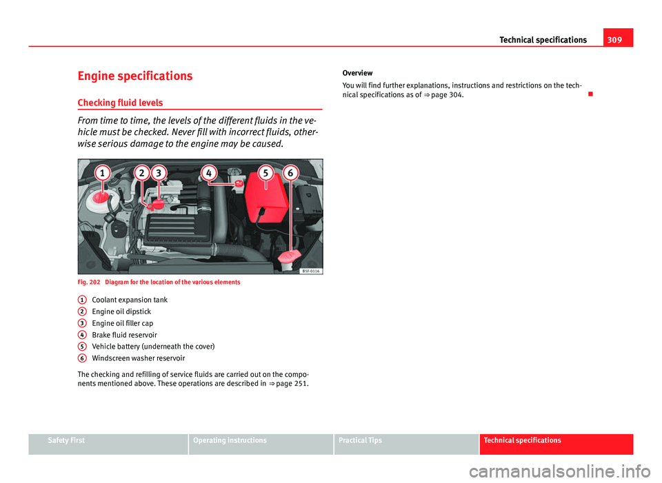
From time to time, the levels of the different fluids in the ve-
hicle must be checked. Never fill with incorrect fluids, other-
wise serious damage to the engine may be caused.
Fig. 202 Diagram for the location of the various elements Coolant expansion tank
Engine oil dipstick
Engine oil filler cap
Brake fluid reservoir
Vehicle battery (underneath the cover)
Windscreen washer reservoir
The checking and refilling of service fluids are carried out on the compo-
nents mentioned above. These operations are described in ⇒ page 251.
1
23456
Overview
You will find further explanations, instructions and restrictions on the tech-
nical specifications as of
⇒ page 304.
Safety FirstOperating instructionsPractical TipsTechnical specifications
Page 330 of 339
E
E10see Ethanol (fuel) . . . . . . . . . . . . . . . . . . . . 246
Easy Connect . . . . . . . . . . . . . . . . . . . . . . . . . . . 79
Economic driving . . . . . . . . . . . . . . . . . . . . . . . 231
EDL see Electronic differential lock . . . . . . . . . 222
Efficiency programme Additional electrical appliances . . . . . . . . . 77
Saving tips . . . . . . . . . . . . . . . . . . . . . . . . . . 78
Electrical accessories see Power socket . . . . . . . . . . . . . . . . . . . . 135
Electric windows . . . . . . . . . . . . . . . . . . . . . . . . 102 Convenience opening/closing . . . . . . . . . 103
Electro-mechanical steering . . . . . . . . . . . . . . 225 Warning lamp . . . . . . . . . . . . . . . . . . . . . . . 225
Electronic differential lock . . . . . . . . . . . . . . . . 222
Electronic Self-locking . . . . . . . . . . . . . . . . . . . 222
Electronic Stability Control (ESC) . . . . . . . . . . 222
Emergencies . . . . . . . . . . . . . . . . . . . . . . . . . . . 274 Automatic gearbox Backup programme . . 181
Replacing the battery . . . . . . . . . . . . . . . . . 262
Emergency braking warning . . . . . . . . . . . . . . 114
Emergency locking and unlocking . . . . . . . . . . 98
Engine Assisted starting . . . . . . . . . . . . . . . . . . . . 283
Preheating . . . . . . . . . . . . . . . . . . . . . . . . . 163
Start-Stop system . . . . . . . . . . . . . . . . . . . . 169
Starting up . . . . . . . . . . . . . . . . . . . . . . . . . 163 Starting up (driver messages with the me-
chanical contact) . . . . . . . . . . . . . . . . . . . 164
Switching off (engine) . . . . . . . . . . . . . . . . 165
Engine compartment Closing the bonnet . . . . . . . . . . . . . . . . . . . 253
Opening the bonnet . . . . . . . . . . . . . . . . . . 252
Safety notes . . . . . . . . . . . . . . . . . . . . . . . . 251
Engine coolant G 12 plus-plus . . . . . . . . . . . . . . . . . . . . . . 257
G 13 . . . . . . . . . . . . . . . . . . . . . . . . . . . . . . . 257
Specifications . . . . . . . . . . . . . . . . . . . . . . . 257
Engine oil . . . . . . . . . . . . . . . . . . . . . . . . . . . . . 253 Changing . . . . . . . . . . . . . . . . . . . . . . . . . . 256
Checking oil level . . . . . . . . . . . . . . . . . . . . 255
Consumption . . . . . . . . . . . . . . . . . . . . . . . 255
Engine oil dipstick . . . . . . . . . . . . . . . . . . . 255
Inspection service . . . . . . . . . . . . . . . . . . . 253
Longlife inspection service . . . . . . . . . . . . 253
Oil properties . . . . . . . . . . . . . . . . . . . . . . . 254
Replace . . . . . . . . . . . . . . . . . . . . . . . . . . . . 253
Service intervals . . . . . . . . . . . . . . . . . . . . . 253
Specifications . . . . . . . . . . . . . . . . . . . . . . . 253
Temperature display . . . . . . . . . . . . . . . . . . . 77
Topping up . . . . . . . . . . . . . . . . . . . . . . . . . 256
Environment Ecological driving . . . . . . . . . . . . . . . . . . . . 231
Environmental friendliness . . . . . . . . . . . . 232
Environmental tip Leaks . . . . . . . . . . . . . . . . . . . . . . . . . . . . . . 252
Environmental tips Filling the tank . . . . . . . . . . . . . . . . . . 248, 250
Environment warning . . . . . . . . . . . . . . . . . . . . 219 ESC
Electronic stability control . . . . . . . . . . . . . 222
Multi-collision brake . . . . . . . . . . . . . . . . . 223
Sport Mode . . . . . . . . . . . . . . . . . . . . . . . . . 223
Ethanol (fuel) . . . . . . . . . . . . . . . . . . . . . . . . . . 246
Exhaust tail pipe: Cleaning . . . . . . . . . . . . . . . 242
extending the rear lid locking time see rear lid . . . . . . . . . . . . . . . . . . . . . . . . . 100
Exterior lighting Changing a bulb . . . . . . . . . . . . . . . . . . . . . 293
Exterior mirrors Adjust . . . . . . . . . . . . . . . . . . . . . . . . . . . . . 125
heated . . . . . . . . . . . . . . . . . . . . . . . . . . . . . 125
Heating . . . . . . . . . . . . . . . . . . . . . . . . . . . . 125
F
Fastening rings . . . . . . . . . . . . . . . . . . . . . . 18, 145
Fault in the gearbox (warning lamp) . . . . . . . . 181
Fault memory . . . . . . . . . . . . . . . . . . . . . . . . . . 228
Faults Panoramic sliding sunroof . . . . . . . . . . . . . 106
Faults in the gearbox (warning lamps) . . . . . . 182
Faulty bulbs Changing a bulb . . . . . . . . . . . . . . . . . . . . . 293
Filling the tank . . . . . . . . . . . . . . . . . . . . . . . . . 248 Fuel gauge . . . . . . . . . . . . . . . . . . . . . . . . . . 67
Opening the fuel tank cap . . . . . . . . . . . . . 248
Floor mats . . . . . . . . . . . . . . . . . . . . . . . . . . . . . . 17
Fog light . . . . . . . . . . . . . . . . . . . . . . . . . . . . . . 111
Fold the seats . . . . . . . . . . . . . . . . . . . . . . . . . . . 137
328 Index