brake light Seat Leon Sportstourer 2017 Service Manual
[x] Cancel search | Manufacturer: SEAT, Model Year: 2017, Model line: Leon Sportstourer, Model: Seat Leon Sportstourer 2017Pages: 332, PDF Size: 7.25 MB
Page 230 of 332
Operation
● When mor e att
ention i
s required by the
driver.
● When driving in a very sporty style.
● In adverse weather conditions, e.g. in case
of sno
w or heavy rain.
● When driving on roads in poor condition.
● In sections with roadworks.
● In city journeys. WARNING
The smart technology incorporated into Traf-
fic Jam As s
ist cannot defy the laws of phys-
ics; it only works within the limits of the sys-
tem. Accidents and severe injury may occur if
Traffic Jam Assist is used negligently or invol-
untarily. The system is not a replacement for
driver awareness.
● Adapt your speed and safe distance to the
vehicl
e in front of you at all times to suit the
visibility, weather, road and traffic condi-
tions.
● Do not use Traffic Jam Assist in city jour-
neys.
● Do not u
se Traffic Jam Assist if there is poor
vis
ibility, for example, in case of snow, ice,
rain or loose gravel, or on steep or slippery
sections or flooded roads.
● Do not use Traffic Jam Assist offroad or on
roa
ds where the surface is not firm. Traffic
Jam Assist has been designed for use on
paved roads only. ●
Traffic
Jam Assist does not react to people
or animals or vehicles crossing your path or
that approach you head-on down the same
lane.
● If Traffic Jam Assist does not reduce speed
sufficiently
, brake the vehicle immediately by
applying the pedal.
● If the vehicle continues to move when you
wish it
to stop after a driver intervention
prompt, brake the vehicle by applying the
pedal.
● If driver intervention is requested on the
da
sh panel display, immediately resume con-
trol of the vehicle.
● Keep your hands on the wheel at all times
to be re
ady to intervene in the steering at any
time. The driver is always responsible for
keeping the vehicle in its own lane.
● Always be prepared to take charge of driv-
ing (acc
elerating or braking) yourself. Note
● If T
raffic Jam Assist does not work as de-
scribed in this chapter, stop using it and con-
tact a specialised workshop.
● If the system is faulty, take it to a special-
ised work
shop and have it checked. Emergency Assist
D e
s
cription and operation Emergency Assist detects whether there is in-
activity
b
y the driver and can automatically
keep the car within the lane and stop it alto-
gether if necessary. This way the system can
actively help avoid an accident.
Emergency Assist is an additional function of
Lane Assist ››› page 224 and combines Lane
Assist functions with Adaptive Cruise Control
(ACC) ›››
page 214. Therefore, it is essential
that you read these two chapters carefully
and note the limitations of the systems and
the information about them.
Operation of Emergency Assist
Emergency Assist detects when the driver
ceases to perform any activity and repeatedly
requests that he/she regain active control of
the vehicle, through the use of optical and
acoustic warnings and by applying the
brakes.
If the driver continues to do nothing, the sys-
tem automatically takes over the accelerator,
brakes and steering in order to brake the ve-
hicle and keep it in its lane ››› . When the
Emer g
ency
Assist is actively adjusting, the
hazard warning lights come on ›››
page 145
and the vehicle makes slight zigzag move-
ments in the lane in order to warn other driv-
ers.
228
Page 231 of 332
Driver assistance systems
If the remaining braking distance is suffi-
c ient, if
nec
essary the system slows down the
vehicle until it stops completely and auto-
matically switches on the electronic parking
brake ››› page 183.
Switching the Emergency Assist on and off
The Emergency Assist is switched on auto-
matically when the Lane Assist is switched on
››› page 224.
Technical requirements for using the Emer-
gency Assist
● The adaptive cruise control (ACC) must be
switc
hed on ››› page 214.
● The Lane Assist must be switched on
›››
page 224.
● The selector lever must be in the D/S posi-
tion or in the
Tiptronic selector gate.
● The system must have detected a lane sep-
aration line on both side
s of the vehicle
››› Fig. 218.
The following conditions may cause the
Emergency Assist not to react or to switch off
automatically:
● If the driver accelerates, brakes or moves
the steerin
g wheel.
● If any of the conditions mentioned in
›››
page 229, Technical requirements for us-
ing the Emergency Assist are not fulfilled.●
If any
of the conditions required for opera-
tion of the Lane Assist are not met
››› page 224.
● If any of the conditions necessary for the
adaptiv
e cruise control (ACC) to work are no
longer fulfilled ››› page 214. WARNING
The smart technology incorporated into the
Emerg ency
Assist cannot overcome the limits
imposed by the laws of physics; it only works
within the limits of the system. The driver is
responsible for driving the vehicle.
● Adapt your speed and safe distance to the
vehicl
e in front of you at all times to suit the
visibility, weather, road and traffic condi-
tions.
● Keep your hands on the wheel at all times
to be re
ady to intervene in the steering at any
time.
● The Emergency Assist alone cannot always
avoid acc
idents or serious injuries.
● If the operation of the Emergency Assist is
impaired, f
or example if the radar sensor of
the adaptive cruise control (ACC) or the Lane
Assist camera are covered or have lost their
settings, the system may intervene inoppor-
tunely in braking or in steering.
● The Emergency Assist does not react to
people or anim
al or vehicles crossing your
path or which approach you head-on in the
same lane. WARNING
If the Emergency Assist Intervenes inoppor-
tu nely
, serious accidents and injuries may oc-
cur.
● If the Emergency Assist does not operate
properly, sw
itch off the Lane Assist
››› page 224. Doing so will also switch off the
Emergency Assist.
● Have the system checked by a specialised
workshop
. SEAT recommends visiting a SEAT
dealership for this. Note
● Autom atic
interventions by the Emergency
Assist on the brakes may be interrupted by
pressing the accelerator or brake or by mov-
ing the wheel.
● Hazard warning lights that come on auto-
matica
lly can be switched off by pressing the
accelerator or the break, moving the steering
wheel or pressing the hazard warning light
switch.
● If this occurs, the Emergency Assist may
deceler
ate the vehicle until it comes to a com-
plete stop.
● When the Emergency Assist is activated, it
is on
ly available again after the ignition has
been switched off and back on again. 229
Technical data
Advice
Operation
Emergencies
Safety
Page 244 of 332
Operation
Automatic activation
on
– activ
at
es the Automatic activa-
tion option ››› page 240.
off – deactivates the Automatic ac-
tivation option ››› page 240.
Front volume*
Volume in the front and rear area.
Front sound settings/sharpness*
Frequency (tone) of the sound in the front
area.
Rear volume*
Volume in the rear area.
Rear sound settings/sharpness*
Frequency (tone) of the sound in the rear
area.
Adjust volume
With the parking aid switched on, the active
audio/video source volume will be reduced
to the intensity of the selected setting.
Error messages When the Parking Aid is activated or when it
i
s
sw
itched on, if a message reporting a Park- ing aid error is displayed on the instrument
panel, there i
s a fault in the system.
If the fault doesn't disappear before discon-
necting the ignition, next time that parking
aid is engaged in reverse, it will not be indi-
cated.
Parking System Plus*
If there is a fault in the parking aid system a
message will appear on the instrument panel
indicating the error. In addition the key
LED will blink.
If there is a fault in a sensor, the symbol is
displayed on the Easy Connect display in
front of/behind the vehicle. If a rear sensor is
faulty, only the obstacles in the areas A and
B are displayed
››
›
Fig. 225. If a front sensor
is faulty, only the obstacles in the areas C and
D are displayed.
Hav e the f
au
lt corrected by a specialised
workshop without delay.
Towing bracket In vehicles equipped with a towing bracket
dev
ic
e fr
om the factory, when the trailer is
connected electrically, the Parking Aid rear
sensors will not be activated when reverse
gear is engaged, when the selector lever is
turned to position R or when the button is
pressed. Parking System Plus
The dist
ance to possible obstacles at the rear
of the vehicle will not be displayed on the
screen and nor will it be indicated by means
of audible sound signals.
The Easy Connect system screen will only dis-
play objects detected at the front, and the ve-
hicle's trajectory will be hidden.
Braking while manoeuvring function* 3 Only
valid with Parking System Plus
As
soon as an obstacle is detected while re-
versing, the braking while manoeuvring func-
tion activates the emergency braking. De-
pending on the equipment, the braking while
manoeuvring function can also activate
emergency braking while moving forwards.
The emergency braking function is used to
minimise collisions. Vehicle speed must not
be higher than 10 km/h.
The braked manoeuvre function is active or
inactive when the parking light is lit or off, re-
spectively. If an emergency braking is activa-
ted, the function will remain inactive until the
gear is changed.
The Parking System’s limitations apply.
The braking while manoeuvring function is
controlled in the Easy Connect system with
242
Page 254 of 332
Operation
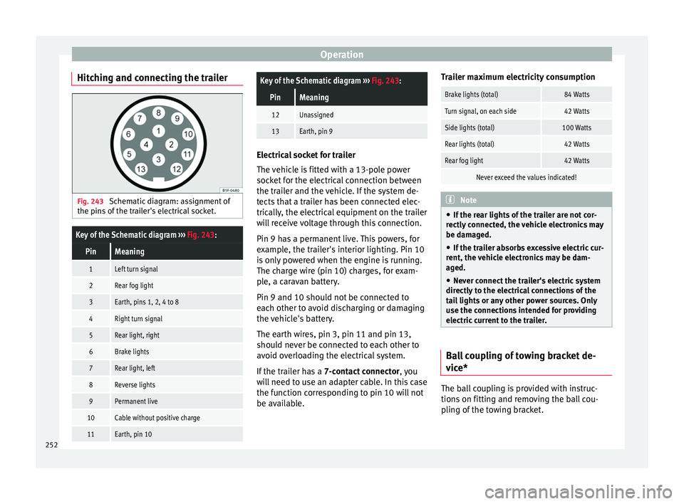
Hitching and connecting the trailer Fig. 243
Schematic diagram: assignment of
the pins of the trailer's electrical socket.
Key of the Schematic diagram ››› Fig. 243:
PinMeaning
1Left turn signal
2Rear fog light
3Earth, pins 1, 2, 4 to 8
4Right turn signal
5Rear light, right
6Brake lights
7Rear light, left
8Reverse lights
9Permanent live
10Cable without positive charge
11Earth, pin 10
Key of the Schematic diagram ››› Fig. 243:
PinMeaning
12Unassigned
13Earth, pin 9 Electrical socket for trailer
The v
ehic
le is fitted with a 13-pole power
socket for the electrical connection between
the trailer and the vehicle. If the system de-
tects that a trailer has been connected elec-
trically, the electrical equipment on the trailer
will receive voltage through this connection.
Pin 9 has a permanent live. This powers, for
example, the trailer's interior lighting. Pin 10
is only powered when the engine is running.
The charge wire (pin 10) charges, for exam-
ple, a caravan battery.
Pin 9 and 10 should not be connected to
each other to avoid discharging or damaging
the vehicle's battery.
The earth wires, pin 3, pin 11 and pin 13,
should never be connected to each other to
avoid overloading the electrical system.
If the trailer has a 7-contact connector , you
will need to use an adapter cable. In this case
the function corresponding to pin 10 will not
be available. Trailer maximum electricity consumption
Brake lights (total)84 Watts
Turn signal, on each side42 Watts
Side lights (total)100 Watts
Rear lights (total)42 Watts
Rear fog light42 Watts
Never exceed the values indicated!
Note
● If the r e
ar lights of the trailer are not cor-
rectly connected, the vehicle electronics may
be damaged.
● If the trailer absorbs excessive electric cur-
rent, the v
ehicle electronics may be dam-
aged.
● Never connect the trailer's electric system
directly t
o the electrical connections of the
tail lights or any other power sources. Only
use the connections intended for providing
electric current to the trailer. Ball coupling of towing bracket de-
v
ic
e* The ball coupling is provided with instruc-
tion
s
on fittin
g and removing the ball cou-
pling of the towing bracket.
252
Page 255 of 332
Towing bracket device
WARNING
The towing bracket ball coupling must be
st or
ed securely in the luggage compartment
to prevent them being flung through the vehi-
cle and causing injury. Note
● By l
aw, the ball coupling must be removed
if a trailer is not being towed if it obscures
the number plate. Driving with a trailer
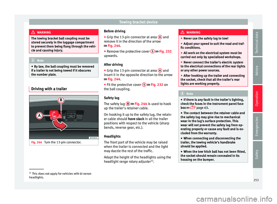
Fig. 244
Turn the 13-pin connector. Before driving
●
Grip the 13-pin connector at area A and
r emo
v
e it in the direction of the arrow
››› Fig. 244.
● Remove the protective cover 5
› ››
Fig. 232
up w
ards.
After driving
● Grip the 13-pin connector at area A and
in ser
t
it in the opposite direction to the arrow
››› Fig. 244.
● Fit the protective cover 5
› ›
› Fig. 232
on
the ball coupling.
Safety lug
The safety lug B
› ›
› Fig. 244
is used to hook
up the trailer's retainer cable.
On hooking it up to the safety lug, the retain-
er cable should have slack in all the trailer
positions with respect to the vehicle (sharp
bends, reverse gear, etc.).
Headlights
The front part of the vehicle may be raised
when the trailer is connected and the light
may dazzle the rest of the traffic.
Adapt the height of the headlights using the
headlight range rotary adjuster 1)
. WARNING
● Never u se the s
afety lug to tow!
● Adjust your speed to suit the road and traf-
fic condition
s.
● All work on the electrical system must be
carried out on
ly by specialised workshops.
● Never connect the trailer's electric system
to the electric
al connections of the rear lights
or any other power sources.
● After hooking up the trailer and connecting
the socket, c
heck that all the trailer's rear
lights are working properly. Note
● If ther e i
s any fault in the trailer's lighting,
check the fuses in the instrument panel fuse
box ›››
page 63.
● The contact between the retainer cable and
the safety
lug may give rise to mechanical
wear in the lug's surface protection. This
wear will not prevent the safety lug from op-
erating properly or cause any fault and is ex-
cluded from the warranty.
● When connecting and disconnecting the
trail
er, the towing vehicle's handbrake
should be applied.
● When the tow hitch ball has not been fitted,
the socket
should remain concealed in its
housing on the bumper. 1)
This does not apply for vehicles with bi-xenon
hea dlights.
253
Technical data
Advice
Operation
Emergencies
Safety
Page 256 of 332
Operation
Anti-theft alarm When the vehicle is locked, the alarm is trig-
ger
ed when the el
ectrical connection be-
tween vehicle and trailer is interrupted.
Always turn off the anti-theft alarm system
before connecting or disconnecting a trailer
››› page 133.
Conditions for the integration of a trailer in
the anti-theft alarm system.
● The vehicle is factory-equipped with an an-
ti-theft al
arm system and a towing bracket
device.
● The trailer is connected electrically to the
tow
ing vehicle by the trailer connector.
● The electrical system of the vehicle and the
trail
er are prepared for operation.
● The vehicle is locked with the ignition key
and the anti-theft al
arm system is activated.CAUTION
For technical reasons, trailers fitted with rear
LED lights ar
e not integrated in the anti-theft
alarm system. Driving tips
Driving with a trailer always requires extra
c
ar e. W
eight distribution
The weight di
stribution of a loaded trailer
with an unladen vehicle is very unfavourable.
However, if this cannot be avoided, drive ex-
tra slowly to allow for the unbalanced weight
distribution.
Speed
The stability of the vehicle and trailer is re-
duced with increasing speed. For this reason,
it is advisable not to drive at the maximum
permissible speed in an unfavourable road,
weather or wind conditions. This applies es-
pecially when driving downhill.
You should always reduce speed immediately
if the trailer shows the slightest sign of snak-
ing. Never try to stop the “snaking” by in-
creasing speed.
Always brake in due course. If the trailer has
an overrun brake, apply the brakes gently at
first and then, firmly. This will prevent the
jerking that can be caused by locking of trail-
er wheels. Select a low gear in due course
before going down a steep downhill. This en-
ables you to use the engine braking to slow
down the vehicle.
Reheating
At very high temperatures and during pro-
longed slopes, driving in a low gear and high
engine speed, always monitor the coolant
temperature gauge ››› page 119. Electronic stability control*
The ESC* sys
tem helps to stabilise the trailer
in case of skidding or rocking.
Retrofitting a towing bracket* Fig. 245
Attachment points for towing brack-
et . 254
Page 260 of 332
Advice
Automatic car washes
B ef
or
e going through a car wash, be sure to
take the usual precautions (closing the win-
dows, roof and rear-view mirrors). If the vehi-
cle has special accessories such as spoilers
or a roof rack or two-way radio aerial, etc., it
is advisable to consult the car wash tunnel
operator.
It is best to use a car wash without revolving
bristles if possible.
Washing the vehicle with a high pressure
cleaner
When washing the vehicle with a high-pres-
sure cleaner, always follow the operating in-
structions for the equipment. This applies
particularly to the operating pressure and the
spraying distance. Do not hold the nozzle too
close to soft materials such as rubber hoses
or seals. The same applies to the parking aid
sensors*, which are located in the rear bump-
er.
Do not use a nozzle that sprays the water out
in a direct stream or one that has a rotating
jet for forcing off dirt.
Factory-fitted adhesive sheets
The following indications should be taken in-
to account to avoid damaging adhesive
sheets:
● Do not use high pressure cleaners. ●
Do not use s crapers to remove ice or snow
from the sheets.
● Do not polish the adhesive sheets.
● Do not use dirty cloths or sponges.
● It is preferable to wash them with a soft
spong
e and gentle neutral soap.
Washing the car by hand
When washing the car by hand, use plenty of
water to soften the dirt first, and rinse off as
well as possible.
Then clean the vehicle with a soft sponge,
glove or brush using only slight pressure.
You should start on the roof and work down.
Special car soap should only be used for very
persistent dirt.
Rinse the sponge or glove thoroughly and of-
ten.
Wheels, sills and similar should be cleaned
last. Use a second sponge for this. WARNING
● The v ehic
le should only be washed with the
ignition switched off. Failure to follow this in-
struction could result in an accident.
● Do not clean the underside of chassis, the
inside of
wheel arches or wheel trims without
protecting your hands and arms. You may cut
yourself on sharp-edged metal parts. Other-
wise, there is a risk of sustaining cuts. ●
When wa shin
g the car during the winter
season: water and ice in the brake system
can reduce braking effectiveness: risk of acci-
dent! CAUTION
● Do not wa
sh the vehicle in direct sunlight –
otherwise the paint can be damaged.
● Do not use sponges, abrasive household
spong
es or similar to clean insect remains.
This could damage the surface.
● Clean off stubborn dirt (insects, etc.) from
the headlight
s at regular intervals, for in-
stance when filling the fuel tank. The head-
lights should only be washed with water, do
not wipe them with a dry cloth or sponge. It
is best to use soapy water.
● Never wash tyres with a jet that sprays the
water out
in a direct stream. This could dam-
age the tyres even if the spray is kept at a
distance and only used for a very short time.
● Before washing the vehicle in an automatic
car wa
sh, please make sure to retract the ex-
terior mirrors to prevent them from being
damaged. Electrically retractable exterior
mirrors must not be folded in or out by hand,
always use the electrical power control. CAUTION
● Bef or
e washing the vehicle in an automatic
car wash, please proceed as follows to lock
the wiper arms so that they are not moved to-
wards the top of the windscreen: 258
Page 263 of 332
Care and maintenance
WARNING
Please note when cleaning the wheels that
wat er
, ice and road salt can impair the effec-
tiveness of the brakes; this can cause an acci-
dent. Exhaust pipe
It is important to remove road salt and brake
dus
t
by washing the wheels at regular inter-
vals, otherwise the exhaust tail pipe material
could be damaged. To remove impurities, do
not use rim, paint or chrome cleaners or oth-
er abrasive products. Clean the exhaust tail
pipes with cleaning products that are suita-
ble for stainless steel.
SEAT Official Services carry stocks of cleaning
products that have been tested and ap-
proved for use on your vehicle.
Caring for the vehicle interior Scr een f
or the radio/Easy Connect*
and control panel* The display can be cleaned with a soft cloth
and a pr
of
e
ssionally available “LCD cleaner”.
Moisten the cloth with a small amount of the
cleaning fluid. The Easy Connect control panel* should first
be cle
aned with a brush so that no dirt goes
into the device or between the keys and
housing. Next, we recommend cleaning the
Easy Connect control panel* using a cloth
dampened with water and washing-up liquid. CAUTION
● To av oid s
cratching the screen, do not wipe
the display with a dry cloth.
● To avoid damage, ensure that no liquid
goes
into the Easy Connect control panel*. Plastic and leatherette parts
Plastic parts and leatherette can be cleaned
w
ith a d
amp c
loth. If this is not sufficient,
plastic parts and leatherette should only be
treated with a special solvent-free plastic
cleaner.
Textile covers and trim parts Textile covers and trim parts (e.g. seats, door
trim) shou
l
d be c
leaned regularly with a vac-
uum cleaner. This will remove surface dirt
which could otherwise be rubbed into the
textile material during use. Do not use steam
cleaners, as the steam could carry the dirt
deeper into the textile material. Normal cleaning
We rec
ommend that you use a soft sponge or
a commercially available lint-free, micro-fibre
cloth for normal cleaning. Only use brushes
on floor coverings and mats, as other textile
surfaces could become damaged.
In the case of normal surface dirt you can use
a foam cleaner. Use a sponge to spread the
foam on the textile surface and to work it into
the material lightly. However, make sure that
the textile material does not become soaking
wet. Then dab off the foam with a dry and ab-
sorbent cloth (e.g. a micro-fibre cloth) and
vacuum off any residue once the surface is
completely dry.
Cleaning stains
Treat drink stains (such as coffee or fruit
juice, etc.) with a cleaning solution for deli-
cate fabrics. This solution should be applied
with a sponge. If the stains are difficult to re-
move, a washing paste can be applied direct-
ly onto the stain and worked into the fabric.
The surface will then have to be wiped with
clear water to remove any residue left by the
paste. To do so, use a damp cloth or sponge
and then dab the stain with an absorbent
cloth.
Remove chocolate or make-up stains with a
cleaning paste (for e.g., soft soap). Then re-
move the soap with water (wet sponge). »
261
Technical data
Advice
Operation
Emergencies
Safety
Page 273 of 332
Checking and refilling levels
●
Tak e c
are not to cause short circuits in the
electrical system, especially when working
on the battery.
● If working inside the engine compartment,
remember that, ev
en when the ignition is
switched off, the radiator fan may start up au-
tomatically, and therefore there is a risk of in-
jury.
● Never cover the engine with additional in-
sul
ating materials such as a blanket. Risk of
fire!
● Do not unscrew the cap on the coolant ex-
pans
ion tank when the engine is hot. The
cooling system is under pressure.
● Protect face, hands and arms by covering
the cap with a l
arge, thick rag to protect
against escaping coolant and steam.
● If it is necessary to work in the engine com-
partment
while the engine is running, the ro-
tating components (for example, poly-V belt,
alternator, radiator fan) and the high voltage
ignition system are an additional hazard.
● Observe the following additional warnings
if work
on the fuel system or the electrical
system is necessary:
– Always disconnect the battery from the
on-board network.
– Do not smoke.
– Never work near naked flames.
– Always keep an approved fire extinguish-
er immediately available. CAUTION
When topping up fluids make sure the correct
fluid is p
ut into the correct filler opening, oth-
erwise this can cause serious malfunctions or
engine damage. For the sake of the environment
Inspect the ground underneath your vehicle
re gu
larly so that any leaks are detected at an
early stage. If you find spots of oil or other
fluids in the area where it was parked, have
your vehicle inspected at the workshop. Note
In right-hand drive vehicles* some brake flu-
id re ser
voirs are on the other side of the en-
gine compartment ››› Fig. 247. Opening the bonnet
Read the additional information carefully
› ›
›
page 17
The bonnet is released from inside the vehi-
cle.
Check that the windscreen wiper arms are
not unfolded. Otherwise the paint may be
damaged.
The bonnet can only be unlocked when the
driver door is open. WARNING
Never open the bonnet if you see steam or
drips of
coolant being released from the en-
gine compartment. Failure to comply could
result in burns. Wait until no steam or coolant
can be seen before opening the bonnet. Closing the bonnet
–
Slightly lift the bonnet.
– Release the bonnet stay before pressing it
bac k
into its support.
– Carefully close the bonnet.
– Press the bonnet down until it locks into
plac
e.
– Make sure that the bonnet catches onto its
cla
sp. Do not press down too hard ››› .
WARNING
● For s af
ety reasons the bonnet must always
be completely closed when the vehicle is
moving. Therefore, after closing the bonnet,
always check that the locking element is
properly engaged. This is the case if the bon-
net is flush with the adjacent body panels.
● Should you notice that the bonnet is not
safely
secured when the vehicle is moving,
stop the vehicle immediately and close the
bonnet. Failure to follow this instruction
could result in an accident. 271
Technical data
Advice
Operation
Emergencies
Safety
Page 277 of 332
Checking and refilling levels
could d amage the engine. If there is no
c oo
lant in the expansion tank, do not con-
tinue driving. You should obtain professio-
nal assistance ››› .
– If there is still some coolant in the expan-
sion t
ank, t
op up to the upper mark.
– Top up with coolant until the level becomes
stab
le.
– Screw the cap back on correctly.
Any lo
ss of coolant fluid normally indicates a
leak in the cooling system. Take the vehicle
straight to a specialised workshop to have
the cooling system examined. If there are no
leaks in the engine cooling system, a loss of
coolant can only occur if the coolant boils
and is forced out of the system as a result of
overheating. WARNING
● The coo lin
g system is under pressure. Do
not unscrew the cap on the coolant expan-
sion tank when the engine is hot: risk of
burns!
● The antifreeze and coolant fluid can be a
health h
azard. Therefore, the antifreeze
should be stored in the original container in a
safe place out of reach of children. Failure to
comply could result in poisoning.
● If working inside the engine compartment,
remember that, ev
en when the ignition is
switched off, the radiator fan may start up au- tomatically, and therefore there is a risk of in-
jury
. WARNING
If there is not enough anti-freeze in the cool-
ant sys
tem, the engine may fail leading to se-
rious damage.
● Please make sure that the percentage of
additiv
e is correct with respect to the lowest
expected ambient temperature in the zone in
which the vehicle is to be used.
● When the outside temperature is very low,
the cool
ant could freeze and the vehicle
would be immobilised. In this case, the heat-
ing would not work either and inadequately
dressed passengers could die of cold. CAUTION
Do not top up the expansion tank with cool-
ant fluid if it
is empty! Air could enter the
cooling system. In this case, stop driving.
Seek specialist assistance. Otherwise, there
is a risk of engine damage. CAUTION
The original additives should never be mixed
with c oo
lants which are not approved by
SEAT. Otherwise, you run the risk of causing
severe damage to the engine and the engine
cooling system.
● If the fluid in the expansion tank is not pur-
ple b
ut is, for example, brown, this indicates that the G13 additive has been mixed with an
ina
dequat
e coolant. The coolant must be
changed as soon as possible if this is the
case! This could result in serious faults and
engine damage. For the sake of the environment
Coolants and additives can contaminate the
en vir
onment. If any fluids are spilled, they
should be collected and correctly disposed
of, with respect to the environment. Brake fluid
Top up br
ak
e fluid Read the additional information carefully
› ›
›
page 61
Checking the brake fluid level
The brake fluid level must be between the
MIN and MAX markings.
However, if the brake fluid level goes down
noticeably in a short time, or drops below the
MIN mark, there may be a leak in the brake
system. Seek specialist assistance. A warn-
ing light on the instrument panel display
monitors the brake fluid level ››› page 119. »
275
Technical data
Advice
Operation
Emergencies
Safety