cooling Seat Leon Sportstourer 2017 Owner's manual
[x] Cancel search | Manufacturer: SEAT, Model Year: 2017, Model line: Leon Sportstourer, Model: Seat Leon Sportstourer 2017Pages: 332, PDF Size: 7.25 MB
Page 7 of 332
Table of Contents
Table of Contents
The e s
senti
als . . . . . . . . . . . . . . . . . . . . . . . . 7
Exterior view . . . . . . . . . . . . . . . . . . . . . . . . . . . . 7
Exterior view . . . . . . . . . . . . . . . . . . . . . . . . . . . . 8
Driver-side general instrument panel (left-
hand drive) . . . . . . . . . . . . . . . . . . . . . . . . . . . . .
9
Driver-side general instrument panel (right-
hand drive) . . . . . . . . . . . . . . . . . . . . . . . . . . . . .
10
Centre console . . . . . . . . . . . . . . . . . . . . . . . . . . 11
Passenger-side general instrument panel (left-
hand drive) . . . . . . . . . . . . . . . . . . . . . . . . . . . . .
12
Passenger-side general instrument panel
(right-hand driv
e) . . . . . . . . . . . . . . . . . . . . . . . . 13
Interior view . . . . . . . . . . . . . . . . . . . . . . . . . . . . 14
How it works . . . . . . . . . . . . . . . . . . . . . . . . . . . . 15
Unlocking and locking . . . . . . . . . . . . . . . . . . . . 15
Before driving . . . . . . . . . . . . . . . . . . . . . . . . . . . 19
Airbags . . . . . . . . . . . . . . . . . . . . . . . . . . . . . . . . 22
Child seats . . . . . . . . . . . . . . . . . . . . . . . . . . . . . 25
Starting the vehicle . . . . . . . . . . . . . . . . . . . . . . 30
Lights and visibility . . . . . . . . . . . . . . . . . . . . . . 30
Easy Connect . . . . . . . . . . . . . . . . . . . . . . . . . . . 33
Driver information System . . . . . . . . . . . . . . . . . 36
Status display . . . . . . . . . . . . . . . . . . . . . . . . . . . 41
Cruise control . . . . . . . . . . . . . . . . . . . . . . . . . . . 45
Warning lamps . . . . . . . . . . . . . . . . . . . . . . . . . . 47
Gearbox lever . . . . . . . . . . . . . . . . . . . . . . . . . . . 50
Air conditioning . . . . . . . . . . . . . . . . . . . . . . . . . 52
Fluid Level control . . . . . . . . . . . . . . . . . . . . . . . 58
Emergencies . . . . . . . . . . . . . . . . . . . . . . . . . . . . 63
Fuses . . . . . . . . . . . . . . . . . . . . . . . . . . . . . . . . . . 63
Bulbs . . . . . . . . . . . . . . . . . . . . . . . . . . . . . . . . . . 64
Action in the event of a puncture . . . . . . . . . . . 64
Changing a wheel . . . . . . . . . . . . . . . . . . . . . . . 66
Snow chains . . . . . . . . . . . . . . . . . . . . . . . . . . . . 69
Emergency towing of the vehicle . . . . . . . . . . . 69 How to jump start . . . . . . . . . . . . . . . . . . . . . . . . 70
Changing the wiper blades . . . . . . . . . . . . . . . . 72
Safety . . . . . . . . . . . . . . . . . . . . . . . . . . . . . . . . 74
Safe driving . . . . . . . . . . . . . . . . . . . . . . . . . . . . 74
Safety first! . . . . . . . . . . . . . . . . . . . . . . . . . . . . . 74
Advice about driving . . . . . . . . . . . . . . . . . . . . . 74
Correct position of the vehicle occupants . . . . 75
Pedal area . . . . . . . . . . . . . . . . . . . . . . . . . . . . . . 79
Seat belts . . . . . . . . . . . . . . . . . . . . . . . . . . . . . . 80
Why wear a seat belt . . . . . . . . . . . . . . . . . . . . . 80
How to properly adjust your seatbelt . . . . . . . . 83
Seat belt tensioners . . . . . . . . . . . . . . . . . . . . . . 84
Airbag system . . . . . . . . . . . . . . . . . . . . . . . . . . 85
Brief introduction . . . . . . . . . . . . . . . . . . . . . . . . 85
Safety instructions about airbags . . . . . . . . . . . 87
Deactivating airbags . . . . . . . . . . . . . . . . . . . . . 89
Transporting children safely . . . . . . . . . . . . . . . 91
Safety for children . . . . . . . . . . . . . . . . . . . . . . . 91
Child seats . . . . . . . . . . . . . . . . . . . . . . . . . . . . . 92
Event Data Recorder . . . . . . . . . . . . . . . . . . . . . . 94
Description and operation . . . . . . . . . . . . . . . . . 94
Emergencies . . . . . . . . . . . . . . . . . . . . . . . . . . 95
Self-help . . . . . . . . . . . . . . . . . . . . . . . . . . . . . . . 95
Vehicle tool kit, anti-puncture kit* . . . . . . . . . . 95
Tyre repair . . . . . . . . . . . . . . . . . . . . . . . . . . . . . . 95
Manual unlocking/locking . . . . . . . . . . . . . . . . . 97
Changing the windscreen wiper blades . . . . . . 97
Towing or tow-starting . . . . . . . . . . . . . . . . . . . . 98
Fuses and bulbs . . . . . . . . . . . . . . . . . . . . . . . . . 101
Fuses . . . . . . . . . . . . . . . . . . . . . . . . . . . . . . . . . . 101
Changing bulbs . . . . . . . . . . . . . . . . . . . . . . . . . 103
Change the front bulbs . . . . . . . . . . . . . . . . . . . 105
Changing incandescent rear light bulbs . . . . . . 107
Side turn signals . . . . . . . . . . . . . . . . . . . . . . . . 110 Operation
. . . . . . . . . . . . . . . . . . . . . . . . . . . . . 113
Controls and displays . . . . . . . . . . . . . . . . . . . . 113
General instrument panel . . . . . . . . . . . . . . . . . 112
Instruments and warning/control lamps . . . . . 114
Instruments . . . . . . . . . . . . . . . . . . . . . . . . . . . . 114
Control lamps . . . . . . . . . . . . . . . . . . . . . . . . . . . 119
Introduction to the Easy Connect system* . . . . 120
System settings (CAR)* . . . . . . . . . . . . . . . . . . . 120
Communications and multimedia . . . . . . . . . . . 121
Steering wheel controls* . . . . . . . . . . . . . . . . . . 121
Multimedia . . . . . . . . . . . . . . . . . . . . . . . . . . . . . 123
Opening and closing . . . . . . . . . . . . . . . . . . . . . 125
Central locking system . . . . . . . . . . . . . . . . . . . . 125
Anti-theft alarm system* . . . . . . . . . . . . . . . . . . 133
Rear lid (luggage compartment) . . . . . . . . . . . . 135
Controls for the windows . . . . . . . . . . . . . . . . . . 136
Panoramic sliding sunroof* . . . . . . . . . . . . . . . . 138
Lights and visibility . . . . . . . . . . . . . . . . . . . . . . 140
Lights . . . . . . . . . . . . . . . . . . . . . . . . . . . . . . . . . 140
Visibility . . . . . . . . . . . . . . . . . . . . . . . . . . . . . . . 148
Windscreen wiper and window wiper sys-
tems . . . . . . . . . . . . . . . . . . . . . . . . . . . . . . . . . . 148 Mirr
or . . . . . . . . . . . . . . . . . . . . . . . . . . . . . . . . . 150
Seats and head restraints . . . . . . . . . . . . . . . . . 152
Adjusting the seats and headrests . . . . . . . . . . 152
Seat functions . . . . . . . . . . . . . . . . . . . . . . . . . . 154
Transport and practical equipment . . . . . . . . . 157
Storage compartments . . . . . . . . . . . . . . . . . . . 157
Storing objects . . . . . . . . . . . . . . . . . . . . . . . . . . 160
Roof carrier . . . . . . . . . . . . . . . . . . . . . . . . . . . . . 170
Air conditioning . . . . . . . . . . . . . . . . . . . . . . . . . 173
Heating, ventilation and cooling . . . . . . . . . . . . 173
Driving . . . . . . . . . . . . . . . . . . . . . . . . . . . . . . . . 178
Starting and stopping the engine . . . . . . . . . . . 178
Braking and parking . . . . . . . . . . . . . . . . . . . . . 183
Braking and stability systems . . . . . . . . . . . . . . 187
Manual gearbox . . . . . . . . . . . . . . . . . . . . . . . . . 190
5
Page 8 of 332
Table of Contents
Automatic gearbox/DSG automatic gear-
bo x*
. . . . . . . . . . . . . . . . . . . . . . . . . . . . . . . . . . . 191
Ad
dress . . . . . . . . . . . . . . . . . . . . . . . . . . . . . . . . 198
Run-in and economical driving . . . . . . . . . . . . . 199
Power management . . . . . . . . . . . . . . . . . . . . . . 201
Engine management and emission control sys-
tem . . . . . . . . . . . . . . . . . . . . . . . . . . . . . . . . . . . 202
Driv
ing tips . . . . . . . . . . . . . . . . . . . . . . . . . . . . . 204
Driver assistance systems . . . . . . . . . . . . . . . . . 205
Start-Stop System* . . . . . . . . . . . . . . . . . . . . . . . 205
Auto Hold Function* . . . . . . . . . . . . . . . . . . . . . . 208
Cruise control system (CCS)* . . . . . . . . . . . . . . . 209
Emergency brake assist system (Front As-
sis
t)* . . . . . . . . . . . . . . . . . . . . . . . . . . . . . . . . . . 210
Adaptive Cruise Control ACC* . . . . . . . . . . . . . . 214
Lane Assist system* . . . . . . . . . . . . . . . . . . . . . . 224
Traffic Jam Assist . . . . . . . . . . . . . . . . . . . . . . . . 227
Emergency Assist . . . . . . . . . . . . . . . . . . . . . . . . 228
SEAT Drive Profile* . . . . . . . . . . . . . . . . . . . . . . . 230
Traffic sign detection system* . . . . . . . . . . . . . . 233
Fatigue detection (break recommendation)* . . 236
Parking aid . . . . . . . . . . . . . . . . . . . . . . . . . . . . . 237
Rear Assist “Rear View Camera”* . . . . . . . . . . . 243
Towing bracket device . . . . . . . . . . . . . . . . . . . . 246
Towing bracket device* . . . . . . . . . . . . . . . . . . . 246
Trailer towing . . . . . . . . . . . . . . . . . . . . . . . . . . . 251
Advice . . . . . . . . . . . . . . . . . . . . . . . . . . . . . . . . 256
Care and maintenance . . . . . . . . . . . . . . . . . . . . 256
Accessories and modifications to the vehi-
cle
. . . . . . . . . . . . . . . . . . . . . . . . . . . . . . . . . . . . 256
Care and cleaning . . . . . . . . . . . . . . . . . . . . . . . 257
Vehicle exterior care . . . . . . . . . . . . . . . . . . . . . . 257
Caring for the vehicle interior . . . . . . . . . . . . . . 261
Checking and refilling levels . . . . . . . . . . . . . . . 264
Filling the tank . . . . . . . . . . . . . . . . . . . . . . . . . . 264
Fuel . . . . . . . . . . . . . . . . . . . . . . . . . . . . . . . . . . . 266
Engine compartment . . . . . . . . . . . . . . . . . . . . . 270 Engine oil . . . . . . . . . . . . . . . . . . . . . . . . . . . . . . 272
Cooling system . . . . . . . . . . . . . . . . . . . . . . . . . . 274
Brake fluid . . . . . . . . . . . . . . . . . . . . . . . . . . . . . 275
Windscreen washer reservoir . . . . . . . . . . . . . . 276
Battery . . . . . . . . . . . . . . . . . . . . . . . . . . . . . . . . . 277
Wheels
. . . . . . . . . . . . . . . . . . . . . . . . . . . . . . . . 279
Wheels and tyres . . . . . . . . . . . . . . . . . . . . . . . . 279
Tyre monitoring systems . . . . . . . . . . . . . . . . . . 283
Temporary spare wheel . . . . . . . . . . . . . . . . . . . 286
Winter service . . . . . . . . . . . . . . . . . . . . . . . . . . . 287
Technical data . . . . . . . . . . . . . . . . . . . . . . . . 289
Technical specifications . . . . . . . . . . . . . . . . . . 289
Important . . . . . . . . . . . . . . . . . . . . . . . . . . . . . . 289
Vehicle identification data . . . . . . . . . . . . . . . . . 289
Fuel consumption data . . . . . . . . . . . . . . . . . . . 290
Trailer mode . . . . . . . . . . . . . . . . . . . . . . . . . . . . 290
Wheels . . . . . . . . . . . . . . . . . . . . . . . . . . . . . . . . 291
Engine data . . . . . . . . . . . . . . . . . . . . . . . . . . . . . 292
Dimensions . . . . . . . . . . . . . . . . . . . . . . . . . . . . . 313
Index . . . . . . . . . . . . . . . . . . . . . . . . . . . . . . . . . 315
6
Page 55 of 332
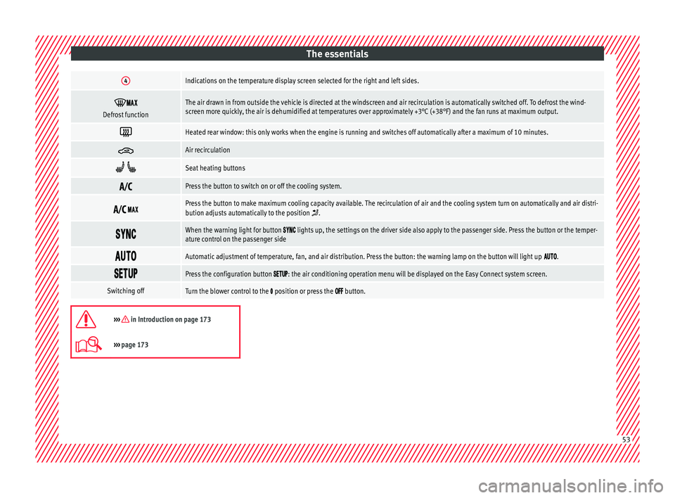
The essentials4Indications on the temperature display screen selected for the right and left sides.
Defrost functionThe air drawn in from outside the vehicle is directed at the windscreen and air recirculation is automatically switched off. To defrost the wind-
screen more quickly, the air is dehumidified at temperatures over approximately +3°C (+38°F) and the fan runs at maximum output.
Heated rear window: this only works when the engine is running and switches off automatically after a maximum of 10 minutes.
Air recirculation
Seat heating buttons
Press the button to switch on or off the cooling system.
Press the button to make maximum cooling capacity available. The recirculation of air and the cooling system turn on automatically and air distri-
bution adjusts automatically to the position .
When the warning light for button lights up, the settings on the driver side also apply to the passenger side. Press the button or the temper-
ature control on the passenger side
Automatic adjustment of temperature, fan, and air distribution. Press the button: the warning lamp on the button will light up .
Press the configuration button : the air conditioning operation menu will be displayed on the Easy Connect system screen.
Switching offTurn the blower control to the position or press the button.
››› in Introduction on page 173
›››
page 173 53
Page 56 of 332
The essentials
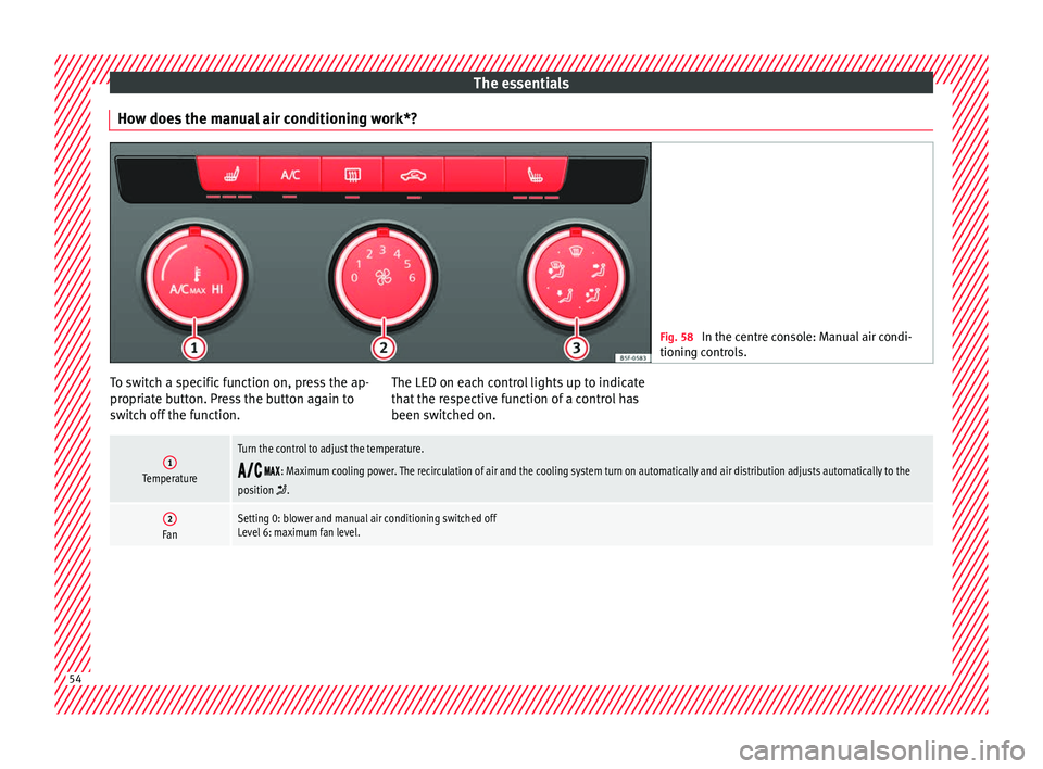
How does the manual air conditioning work*? Fig. 58
In the centre console: Manual air condi-
tioning c ontr
ols. To switch a specific function on, press the ap-
pr
opri
at
e button. Press the button again to
switch off the function. The LED on each control lights up to indicate
that the r
espective function of a control has
been switched on.
1Temperature
Turn the control to adjust the temperature.
: Maximum cooling power. The recirculation of air and the cooling system turn on automatically and air distribution adjusts automatically to the
position .
2FanSetting 0: blower and manual air conditioning switched off
Level 6: maximum fan level. 54
Page 57 of 332
The essentials3Air distribution
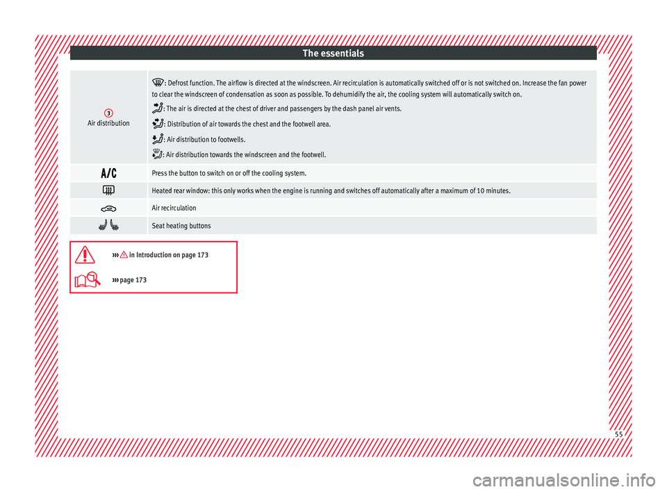
: Defrost function. The airflow is directed at the windscreen. Air recirculation is automatically switched off or is not switched on. Increase the fan power
to clear the windscreen of condensation as soon as possible. To dehumidify the air, the cooling system will automatically switch on.
: The air is directed at the chest of driver and passengers by the dash panel air vents.
: Distribution of air towards the chest and the footwell area.
: Air distribution to footwells.
: Air distribution towards the windscreen and the footwell.
Press the button to switch on or off the cooling system.
Heated rear window: this only works when the engine is running and switches off automatically after a maximum of 10 minutes.
Air recirculation
Seat heating buttons
››› in Introduction on page 173
›››
page 173 55
Page 62 of 332
The essentials
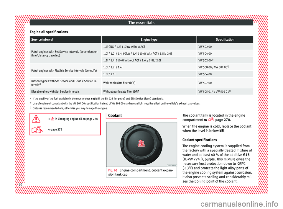
Engine oil specificationsService intervalEngine typeSpecification
Petrol engines with Set Service Intervals (dependent on
time/distance travelled)1.4l CNG / 1.4l 110kW without ACTVW 502 00
1.0l / 1.2l / 1.4l 92kW / 1.4l 110kW with ACT / 1.8l / 2.0lVW 504 00
1.2l / 1.4l 110kW without ACT / 1.6l / 1.8l / 2.0lVW 502 00 a)
Petrol engines with Flexible Service Intervals (LongLife)1.0l / 1.2l / 1.4lVW 508 00 / VW 504 00 b)
1.8l / 2.0lVW 504 00
Diesel engines with Set Service and Flexible Service In-
tervalsc)With particulate filter (DPF)VW 507 00
Diesel engines with Set Service IntervalsWithout particulate filter (DPF)VW 505 01 a)
/ VW 506 01 a)
a)
If the quality of the fuel available in the country does not fulfil the EN 228 (for petrol) and EN 590 (for diesel) standards.
b) Use of engine oil compliant with the VW 504 00 specification instead of VW 508 00 may have a slight negative effect on the vehicle’s exhaust gas values.
c) Only use recommended oils, otherwise you may damage the engine.
››› in Changing engine oil on page 274
››› page 272 Coolant
Fig. 63
Engine compartment: coolant expan-
s ion t
ank
cap. The coolant tank is located in the engine
c
omp
ar
tment ›››
page 270.
When the engine is cold, replace the coolant
when the level is below .
Coolant specifications
The engine cooling system is supplied from
the factory with a specially treated mixture of
water and at least 40 % of the additive G13
(TL-VW 774 J), purple. This mixture gives the
necessary frost protection down to -25°C
(-13°F) and protects the light alloy parts of
the engine cooling system against corrosion.
It also prevents scaling and considerably rai-
ses the boiling point of the coolant. 60
Page 63 of 332
The essentials
To protect the cooling system, the percentage
of a
d
ditive must always be at least 40 %,
even in warm climates where anti-freeze pro-
tection is not required.
If for weather reasons further protection is
necessary, the proportion of additive may be
increased, but only up to 60 %; otherwise an-
tifreeze protection will diminish and this will
worsen cooling.
When the coolant is topped up, use a mixture
of distilled water and at least 40 % of the
G13 or G12 plus-plus (TL-VW 774 G) additive
(both are purple) to obtain an optimum anti-
corrosion protection ››› in Topping up cool-
ant on p ag
e 275
. The mixture of G13 with
G12 plus (TL-VW 774 F), G12 (red) or G11
(green-blue) engine coolants will significant-
ly reduce anti-corrosion protection and
should therefore be avoided ››› in Topping
up c oo
l
ant on page 275.
››› in Topping up coolant on page 275
››› page 274 Brake fluid
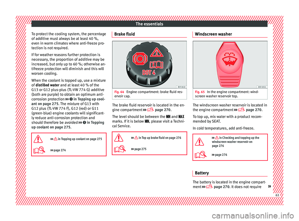
Fig. 64
Engine compartment: brake fluid res-
er v
oir c
ap. The brake fluid reservoir is located in the en-
gine c
omp
ar
tment ›››
page 270
.
The level should be between the and
marks. If it is below , please visit a Techni-
cal Service.
››› in Top up brake fluid on page 276
››› page 275 Windscreen washer
Fig. 65
In the engine compartment: wind-
s c
r
een washer reservoir top. The windscreen washer reservoir is located in
the en
gine c
omp
artment ›››
page 270.
To top up, mix water with a product recom-
mended by SEAT.
In cold temperatures, add anti-freeze.
››› in Checking and topping up the
windscreen washer reservoir on
page 276
››› page 276 Battery
The battery is located in the engine compart-
ment
›
›
› page 270. It does not require » 61
Page 120 of 332
Operation
For vehicles with no coolant temperature
g aug
e, a c
ontrol lamp appears for high
coolant temperatures ››› page 274. Please
note ››› .
The c oo
l
ant temperature gauge only works
when the ignition is switched on ››› Fig. 124.
In order to avoid engine damage, please read
the following notes for the different tempera-
ture ranges.
Engine cold
If only the diodes in the lower part of the
scale light up, this indicates that the engine
has not yet reached operating temperature.
Avoid high revs and heavy acceleration and
do not make the engine work hard.
Normal temperature
If in normal operations, the diodes light up
until the central zone, it means that the en-
gine has reached operating temperature. At
high outside temperatures and when making
the engine work hard, the diodes may contin-
ue lighting up and reach the upper zone. This
is no cause for concern, provided the control
lamp does not light up on the instrument
panel digital display.
Heat range
When the diodes light up in the upper area of
the display and the control lamp appears on the instrument panel display, the coolant
temperat
ure is excessive ››› page 274. CAUTION
● To en s
ure a long useful life for the engine,
avoid high revs, driving at high speed and
making the engine work hard for approxi-
mately the first 15 minutes when the engine
is cold. The phase until the engine is warm al-
so depends on the outside temperature. If
necessary, use the engine oil temperature*
››› page 43 as a guide.
● Additional lights and other accessories in
front of
the air inlet reduce the cooling effect
of the coolant. At high outside temperatures
and high engine loads, there is a risk of the
engine overheating.
● The front spoiler also ensures proper distri-
bution of the c
ooling air when the vehicle is
moving. If the spoiler is damaged this can re-
duce the cooling effect, which could cause
the engine to overheat. Seek specialist assis-
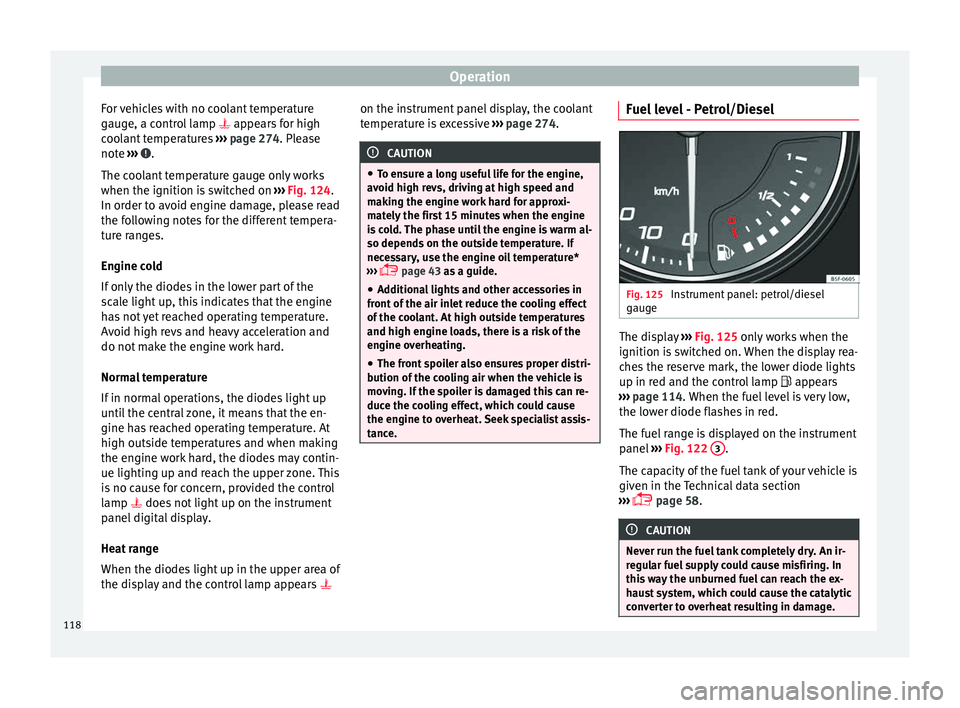
tance. Fuel level - Petrol/Diesel
Fig. 125
Instrument panel: petrol/diesel
g aug
e The display
››
› Fig. 125
only works when the
ignition is switched on. When the display rea-
ches the reserve mark, the lower diode lights
up in red and the control lamp appears
››› page 114. When the fuel level is very low,
the lower diode flashes in red.
The fuel range is displayed on the instrument
panel ››› Fig. 122 3 .
The c ap
ac
ity of the fuel tank of your vehicle is
given in the Technical data section
››› page 58. CAUTION
Never run the fuel tank completely dry. An ir-
re gu
lar fuel supply could cause misfiring. In
this way the unburned fuel can reach the ex-
haust system, which could cause the catalytic
converter to overheat resulting in damage. 118
Page 121 of 332
Instruments and warning/control lamps
Fuel - Natural Gas level 3 Valid in vehicles equipped with natural gas engine
(GNC)
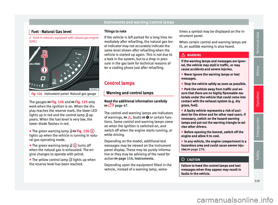
Fig. 126
Instrument panel: Natural gas gauge The gauges
››
› Fig. 126 and ››› Fig. 125 only
work when the ignition is on. When the dis-
play reaches the reserve mark, the lower LED
lights up in red and the control lamp ap-
pears. When the fuel level is very low, the
lower diode flashes in red.
● The green warning lamp ›››
Fig. 126 1 lights up when the vehicle is running in natu-
r
al
g
as operating mode.
● The green warning lamp 1 turns off
when the n at
ur
al gas is exhausted. The en-
gine changes to operate with petrol.
● The yellow control lamp lights up when
the re
serve level has been reached. Things to note
If the v
ehicle is left parked for a long time im-
mediately after refuelling, the natural gas lev-
el indicator may not accurately indicate the
same level shown after refuelling when the
vehicle is started up again. This is not due to
a leak in the system, but to a drop in pres-
sure in the gas tank for technical reasons af-
ter a cooling phase just after refuelling.
Control lamps
Warning and c
ontrol lamps Read the additional information carefully
› ›
›
page 47.
The control and warning lamps are indicators
of warnings, ››› , faults
››
› or certain func-
tion s.
Some c
ontrol and warning lamps come
on when the ignition is switched on, and
switch off when the engine starts running, or
while driving.
Depending on the model, additional text
messages may be viewed on the instrument
panel display. These may be purely informa-
tive or they may be advising of the need for
action ›››
page 114, Instruments.
Depending upon the equipment fitted in the
vehicle, instead of a warning lamp, some- times a symbol may be displayed on the in-
strument p
anel.
When certain control and warning lamps are
lit, an audible warning is also heard. WARNING
If the warning lamps and messages are ignor-
ed, the v ehic
le may stall in traffic, or may
cause accidents and severe injuries.
● Never ignore the warning lamps or text
mess
ages.
● Stop the vehicle safely as soon as possible.
● Park the vehicle away from traffic and en-
sure th
at there are no highly flammable ma-
terials under the vehicle that could come into
contact with the exhaust system (e.g. dry
grass, fuel).
● A faulty vehicle represents a risk of acci-
dent for the driv
er and for other road users. If
necessary, switch on the hazard warning
lamps and put out the warning triangle to ad-
vise other drivers.
● Before opening the bonnet, switch off the
engine and al
low it to cool.
● In any vehicle, the engine compartment is a
hazar
dous area and could cause severe inju-
ries ››› page 270. CAUTION
Failure to heed the control lamps and text
mes s
ages when they appear may result in
faults in the vehicle. 119
Technical data
Advice
Operation
Emergencies
Safety
Page 175 of 332
Air conditioning
Distributing a load
Di s
trib
ute loads uniformly and secure them
correctly ››› .
Chec k
att
achments
Once the cross bars and roof carrier system
have been installed, check the bolted con-
nections and attachments after a short jour-
ney and subsequently with a certain frequen-
cy. WARNING
Exceeding the maximum authorised roof load
can r e
sult in accidents and considerable vehi-
cle damage.
● Never exceed the maximum authorised
load on the r
oof and on the axles or the vehi-
cle's maximum authorised weight.
● Never exceed the load capacity of the cross
bars
and the roof carrier system, even if the
maximum authorised roof load has not been
reached.
● Secure heavy items as far forward as possi-
ble and di
stribute the vehicle load uniformly. WARNING
If the load is loose or not secured, it could fall
from the r oof
carrier system or cause acci-
dents and injuries.
● Always use belts or retaining straps that
are suit
able and in a good condition.
● Secure the load properly. Air conditioning
He atin
g,
ventilation and cool-
ing
Introduction Read the additional information carefully
›› ›
page 52
Viewing Climatronic information
On the screen of Climatronic control unit and
on the screen of the factory-fitted Easy Con-
nect system, the theoretical values of the
temperature zones are shown.
The unit of temperature measurement can be
changed in the Easy Connect system.
Dust and pollen filter
The dust and pollen filter with its activated
charcoal cartridge serves as a barrier against
impurities in the air taken into the vehicle in-
terior.
The dust and pollen filter must be changed
regularly so that air conditioner performance
is not adversely affected.
If the filter loses efficiency prematurely due
to use in areas with very high levels of air
pollution, the filter must be changed more
frequently than stated in the Service Sched-
ule. WARNING
Reduced visibility through the windows in-
cr e
ases the risk of serious accidents.
● Always ensure that all windows are free of
ice and sno
w, and that they are not fogged,
so as to maintain good visibility of everything
outside.
● The maximum heat output required to de-
fros
t windows as quickly as possible is only
available when the engine has reached its
normal running temperature. Only drive when
you have good visibility.
● Always ensure that you use the heating
syst
em, fresh air system, air conditioner and
the heated rear window to maintain good visi-
bility to the outside.
● Never leave the air recirculation on for a
long period of time. If
the cooling system is
switched off and air recirculation mode
switched on, the windows can mist over very
quickly, considerably limiting visibility.
● Switch air recirculation mode off when it is
not requir
ed. WARNING
Stuffy or used air will increase fatigue and re-
duce driv er c
oncentration possibly resulting
in a serious accident.
● Never leave the fresh air fan turned off or
use the air rec
irculation for long periods of
time; the air in the vehicle interior will not be
refreshed. » 173
Technical data
Advice
Operation
Emergencies
Safety