diagram Seat Mii 2012 Owner's manual
[x] Cancel search | Manufacturer: SEAT, Model Year: 2012, Model line: Mii, Model: Seat Mii 2012Pages: 308, PDF Size: 4.13 MB
Page 263 of 308

261
Practical information
Fuses
Introduction
Due to the constant update of vehicles, fuse assignments depending on
equipment and the use of the same fuse for various electrical components,
at the time of printing this manual it is not possible to provide an up-to-date
summary of the electrical components fuse positions. For detailed informa-
tion about the fuse positions, please consult a Technical Service.
In general, a fuse can be assigned to various electrical components. Like-
wise, an electrical component can be protected by several fuses.
Only replace fuses when the cause of the problem has been solved. +If a
newly inserted fuse blows after a short time, you must have the electrical
system checked by a Specialised workshop as soon as possible.
Additional information and warnings:
● Working in the engine compartment ⇒ page 180
WARNING
The high voltages in the electrical system can give serious electrical
shocks, causing burns and even death!
● Never touch the electrical wiring of the ignition system.
● Take care not to cause short circuits in the electrical system.
WARNING
Using unsuitable fuses, repairing fuses or bridging a current circuit with-
out fuses can cause a fire and serious injury.
● Never use a fuse with a higher value. Only replace fuses with a fuse of
the same amperage (same colour and markings) and size.
● Never repair a fuse.
● Never replace a fuse by a metal strip, staple or similar.
CAUTION
● To avoid damage to the vehicles electric system, before replacing a fuse
turn off the ignition, the lights and all electrical elements and remove the
keys from the ignition.
● If you replace a fuse with higher-rating fuse, you could cause damage to
another part of the electrical system.
● Protect the fuse boxes when open to avoid the entry of dust or humidity.
Dirt and humidity inside fuse boxes can cause damage to the electrical sys-
tem.
Note
One single consumer could have more than one fuse.
Note
Several consumers could run over one single fuse.
Vehicle diagramPrior to a journey...While drivingCare, cleaning and mainte-
nanceIf and whenTechnical Data
Page 265 of 308

263
Practical information
CAUTION
● Always carefully remove the fuse box covers and refit them correctly to
avoid problems with your vehicle.
● Protect the fuse boxes when open to avoid the entry of dust or humidity.
Dirt and humidity inside fuse boxes can cause damage to the electrical sys-
tem.
Note
In the vehicle, there are more fuses than those indicated in this chapter.
These should only be changed by a Specialised workshop.
Replacing a blown fuse
Fig. 149 Image of a
blown fuse
Preparation
● Switch off the ignition, lights and all electrical equipment.
● Open the corresponding fuse box ⇒ page 262. Identifying a blown fuse
A fuse is blown if its metal strip is ruptured
⇒ Fig. 149.
Point a lamp at the fuse. This will make it easier to see if the fuse is blown.
To replace a fuse
● Remove the fuse.
● Replace the blown fuse for one with an identical amperage rating (same
colour and markings) and identical size ⇒
.
● Replace the cover again or close the fuse box lid.
CAUTION
If you replace a fuse with higher-rating fuse, you could cause damage to an-
other part of the electrical system.
Vehicle diagramPrior to a journey...While drivingCare, cleaning and mainte-
nanceIf and whenTechnical Data
Page 267 of 308

265
Practical information
Information for replacing bulbs
Checklist
To replace a bulb, carry out the following operations always in the order giv-
en ⇒
:
1. Park the vehicle a safe distance from traffic and on suitable ground.
2. Apply the handbrake firmly ⇒ page 134.
3. Turn the light switch to position 0 ⇒ page 84.
4. Move the gear lever into the neutral position ⇒ page 84.
5. Stop the engine and remove the key from the ignition ⇒ page 119.
6. Automatic gearbox: move the selector lever to position P
⇒ page 124.
7. Manual gearbox: Select a gear ⇒ page 124.
8. Allow the corresponding bulb to cool.
9. Visually inspect fuses to see if any are blown ⇒ page 261.
10. Replace the bulb according to the instructions ⇒
. Bulbs should
only be replaced by new identical models. Bulb information is dis-
played on the bulb socket or on the bulb itself.
11. In general, never touch the bulb glass directly. The heat of the bulb would cause the fingerprint to evaporate and condense on the reflec-
tor. This will impair the brightness of the headlight.
12. Check if the new bulb is working. If the bulb is not working, it maynot have been correctly fitted, it could be damaged or the connector
may not be correctly connected.
13. Every time a bulb for the headlights is replaced, visit a specialised workshop to check the headlights.
WARNING
Failure to follow the checklist prepared for your own safety could lead to
accidents and severe injuries.
● Always complete the operations given in the checklist and observe
the general rules of safety.
CAUTION
Always remove and fit headlights carefully to avoid damage to the paint-
work and other vehicle parts.
Vehicle diagramPrior to a journey...While drivingCare, cleaning and mainte-
nanceIf and whenTechnical Data
Page 269 of 308

267
Practical information
Complete operations only in the sequence given:
⇒ Fig. 150ABCDipped beam and main beam headlightsSide light and daytime driving lightTurn signals (front)
6.Insert the bulb, return it to its position and
insert the retaining clip D.Insert the bulb holder in the headlight and
turn it clockwise as far as the stop.Insert the bulb holder in the headlight and
turn it clockwise as far as the stop.
7.Place the rubber cover and check that is
correctly in position. Insert the connector to the bulb H4.
Note
The images show the left hand headlight from behind. The structure of the
right hand side headlight is symmetric.
Replacing the front bumper bulbs
Fig. 151 In the front
right wheel arch: Remove
the retaining screws (ar-
rows) and take out the
expansive rivet A
.
Fig. 152 Changing the
bulbs in the headlights
Complete operations only in the sequence given:
1.Always take the checklist into account and take the necessary ac-
tions
⇒ page 265.
2.Unscrew the 2 retaining screws of the wheel arch trim ⇒ Fig. 151
(arrows) with the screwdriver from the vehicle took kit ⇒ page 246.
3.Unscrew the expansive rivet in the lower front part of the wheel arch
trim A with the screwdriver from the vehicle tool kit and complete-
ly remove it ⇒ page 246.
4.Carefully fold the wheel arch trim to the side.5.Release the connector ⇒ Fig. 152 1 and remove it.
Vehicle diagramPrior to a journey...While drivingCare, cleaning and mainte-
nanceIf and whenTechnical Data
Page 271 of 308
269
Practical information
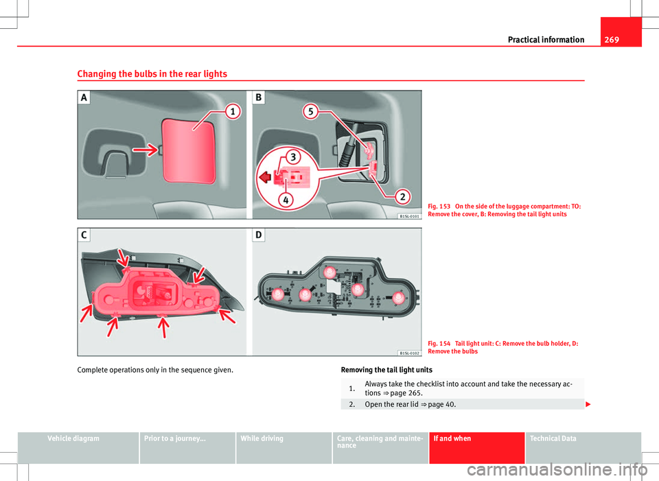
Changing the bulbs in the rear lights
Fig. 153 On the side of the luggage compartment: TO:
Remove the cover, B: Removing the tail light units
Fig. 154 Tail light unit: C: Remove the bulb holder, D:
Remove the bulbs
Complete operations only in the sequence given. Removing the tail light units
1.Always take the checklist into account and take the necessary ac-
tions
⇒ page 265.
2.Open the rear lid ⇒ page 40.
Vehicle diagramPrior to a journey...While drivingCare, cleaning and mainte-
nanceIf and whenTechnical Data
Page 273 of 308
271
Practical information
Only carry out the operations in the sequence indicated:
1.Always take the checklist into account and take the necessary ac-
tions ⇒ page 265.
2.With one hand, press on the number plate light from left to right
and remove it from the bumper ⇒ Fig. 155.
3.Detach the number plate light carefully from the bumper.
4.Turn the bulb holder with the bulb anticlockwise and remove it in
the direction of the arrow ⇒ Fig. 156.
5.Replace the faulty bulb by a new identical bulb.
6.Place the bulb holder in the number plate light and press in the op-
posite direction to the arrow as far as possible ⇒ Fig. 156.
7.
Insert the number plate light carefully into the left edge of the open-
ing on the bumper. During this process, check that the assembly di-
rection of the number plate light is correct, i.e. the spring must be
on the right.
8.Insert the number plate light into the bumper until it audibly clicks
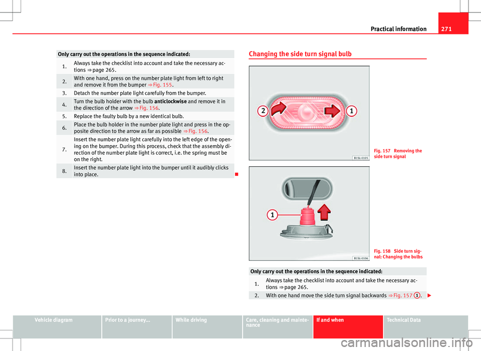
into place.Changing the side turn signal bulb
Fig. 157 Removing the
side turn signal
Fig. 158 Side turn sig-
nal: Changing the bulbs
Only carry out the operations in the sequence indicated:
1.Always take the checklist into account and take the necessary ac-
tions
⇒ page 265.
2.With one hand move the side turn signal backwards ⇒ Fig. 157 1.
Vehicle diagramPrior to a journey...While drivingCare, cleaning and mainte-
nanceIf and whenTechnical Data
Page 275 of 308
273
Practical information
Starting assistance
Introduction
If the engine fails to start because of a discharged battery, the battery of an-
other vehicle can be used to start the engine. Before starting, check the
magic eye on the battery ⇒ page 193.
For starting assistance, jump lead cables conforming to the standard
DIN 72553 are required (see the cable manufacturer instructions). The cable
section in vehicles with petrol engine must be at least 25 mm 2
.
Additional information and warnings:
● Working in the engine compartment ⇒ page 180
● Vehicle battery ⇒ page 193
WARNING
Incorrect use of jump leads and incorrectly jump starting could cause the
battery to explode resulting in serious injury. Please observe the follow-
ing rules to minimise the risk of a battery explosion:
● All work involving the vehicle battery and electrical system can cause
corrosion, fire and serious electric shocks. Always read and take into ac-
count the safety warnings and standards before beginning work on the
battery ⇒ page 193, Vehicle battery.
● The battery providing current must have the same voltage (12V) and
approximately the same capacity (see markings on battery) as the flat
battery.
● Never charge a frozen or recently thawed battery. A flat battery can al-
so freeze at temperatures close to 0 °C (+32 °F).
● If a battery is frozen and/or has been frozen then it must be replaced.
WARNING (Continued)
● A highly explosive mixture of gases is released when the battery is
being charged. Always keep lit cigarettes, open flames, sparks and fire
far from the battery. Never use a mobile telephone when connecting and
removing the jump leads.
● Charge the battery only in well ventilated areas given that when the
battery is charged by outside assistance, it creates a mix of highly explo-
sive gases.
● Jump leads should never enter into contact with moving parts in the
engine compartment.
● Never switch the positive and negative poles or connect the jump
leads incorrectly.
● Note the Instruction Manual provided by the manufacturer of the
jump leads.
CAUTION
To avoid considerable damage to the vehicle electrical system, note the fol-
lowing carefully:
● If the jump leads are incorrectly connected, this could result in a short
circuit.
● The vehicles must not touch each other, otherwise electricity could flow
as soon as the positive terminals are connected.
Vehicle diagramPrior to a journey...While drivingCare, cleaning and mainte-
nanceIf and whenTechnical Data
Page 276 of 308
274Practical information
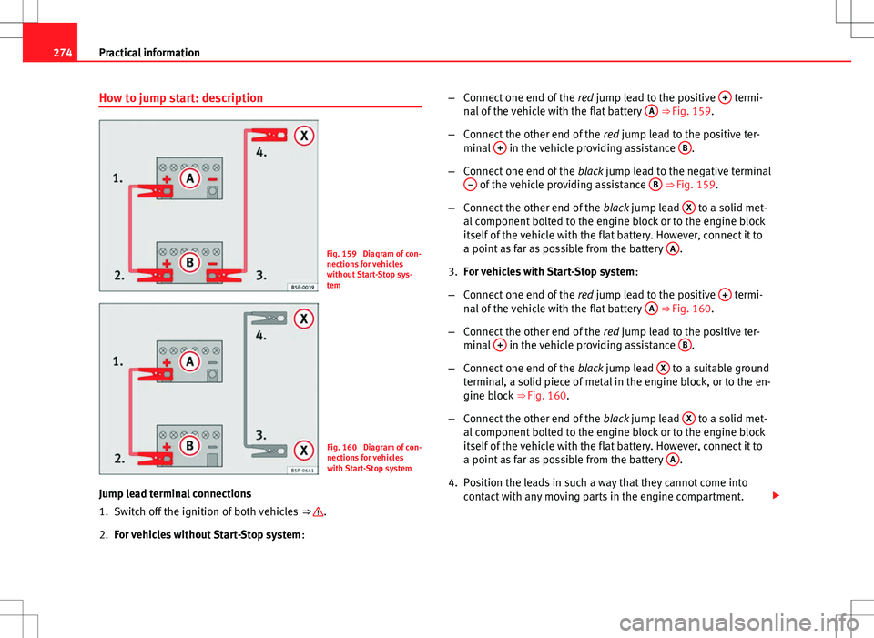
How to jump start: description
Fig. 159 Diagram of con-
nections for vehicles
without Start-Stop sys-
tem
Fig. 160 Diagram of con-
nections for vehicles
with Start-Stop system
Jump lead terminal connections
1. Switch off the ignition of both vehicles ⇒
.
2. For vehicles without Start-Stop system :–
Connect one end of the red jump lead to the positive +
termi-
nal of the vehicle with the flat battery A ⇒ Fig. 159.
– Connect the other end of the red jump lead to the positive ter-
minal +
in the vehicle providing assistance B.
– Connect one end of the black jump lead to the negative terminal
–
of the vehicle providing assistance B ⇒ Fig. 159.
– Connect the other end of the black jump lead X
to a solid met-
al component bolted to the engine block or to the engine block
itself of the vehicle with the flat battery. However, connect it to
a point as far as possible from the battery A
.
3. For vehicles with Start-Stop system :
– Connect one end of the red jump lead to the positive +
termi-
nal of the vehicle with the flat battery A ⇒ Fig. 160.
– Connect the other end of the red jump lead to the positive ter-
minal +
in the vehicle providing assistance B.
– Connect one end of the black jump lead X
to a suitable ground
terminal, a solid piece of metal in the engine block, or to the en-
gine block ⇒ Fig. 160.
– Connect the other end of the black jump lead X
to a solid met-
al component bolted to the engine block or to the engine block
itself of the vehicle with the flat battery. However, connect it to
a point as far as possible from the battery A
.
4. Position the leads in such a way that they cannot come into contact with any moving parts in the engine compartment.
Page 277 of 308
275
Practical information
Starting
5. Start the engine of the vehicle with the boosting battery and let it run at idling speed.
6. Start the engine of the vehicle with the flat battery and wait one or two minutes until the engine is “running”.
Removing the jump leads
7. Before you remove the jump leads, switch off the headlights (if they are switched on).
8. When the engine is running, disconnect the leads in reverse or- der to the details given above.
Connect the battery clamps so they have good metal-to-metal contact with
the battery terminals.
If the engine fails to start, switch off the starter after about 10 seconds and
try again after about half a minute.
WARNING
● Please note the safety warnings referring to working in the engine
compartment ⇒ page 182.
● The battery providing assistance must have the same voltage as the
flat battery (12V) and approximately the same capacity (see imprint on
battery). Failure to comply could result in an explosion.
● Never use jump leads when one of the batteries is frozen. Danger of
explosion! Even after the battery has thawed, battery acid could leak and
cause chemical burns. If a battery freezes, it should be replaced.
● Keep sparks, flames and lighted cigarettes away from batteries, dan-
ger of explosion. Failure to comply could result in an explosion.
WARNING (Continued)
● Observe the instructions provided by the manufacturer of the jump
leads.
● Do not connect the negative cable from the other vehicle directly to
the negative terminal of the flat battery. The gas emitted from the battery
could be ignited by sparks. Danger of explosion.
● Do not attach the negative cable from the other vehicle to parts of the
fuel system or to the brake line.
● The non-insulated parts of the battery clamps must not be allowed to
touch. The jump lead attached to the positive battery terminal must not
touch metal parts of the vehicle, this can cause a short circuit.
● Position the leads in such a way that they cannot come into contact
with any moving parts in the engine compartment.
● Do not bend over the batteries. This could result in chemical burns.
Note
The vehicles must not touch each other, otherwise electricity could flow as
soon as the positive terminals are connected.
Vehicle diagramPrior to a journey...While drivingCare, cleaning and mainte-
nanceIf and whenTechnical Data
Page 279 of 308
277
Practical information
Instructions for tow starting
In general, the vehicle should not be started by towing. Jump-starting is
much more preferable ⇒ page 273.
For technical reasons, the following vehicles can not be tow started:
● Vehicles with an automatic gearbox.
● If the vehicle battery is flat, it is possible that the engine control unit
does not operate correctly.
However, if your vehicle must absolutely be tow-started (manual gearbox):
● Engage the 2nd or 3rd gear.
● Keep the clutch pressed down.
● Switch on the ignition and the hazard warning lights.
● Release the clutch when both vehicles are moving.
● As soon as the engine starts, press the clutch and move the gear lever
into neutral. This helps to prevent a collision with the towing vehicle.
CAUTION
When tow-starting, fuel could enter the catalytic converter and damage it.
Notes on towing
Tow rope or tow bar
When towing, the tow bar is the safest and vehicle friendly way. You should
only use a tow rope if you do not have a tow bar.
A tow rope should be slightly elastic to avoid damage to both vehicles. It is
advisable to use a tow rope made of synthetic fibre or similarly elastic mate-
rial. Only secure the tow rope or tow bar to the tow ring or specially designed
fitting.
Towing vehicles with an automatic gearbox
Note the following for a towed vehicle:
●
Make sure the gear selector lever is in the N position.
● Do not drive faster than 50 km/h (30 mph) when towing a vehicle.
● Do not tow further than 50 km (30 miles).
● If a breakdown truck is used, the vehicle must be towed with the front
wheels raised.
Situations in which the vehicle should not be towed
In the following cases, the vehicle should not be towed but transported on a
trailer or special vehicle:
● If the vehicle gearbox does not contain lubricant due to a fault.
● If the battery is flat as the steering cannot be unlocked, as a result, the
electronic steering lock and electronic parking brake cannot be disengaged.
● If the vehicle to be towed has an automatic gearbox and the distance to
be covered is greater than 50 km (30 miles).
Note
The vehicle can only be towed if the steering lock electronic gearbox lock is
deactivated. If the vehicle has no power supply or there is an electric system
fault, the engine must be started using jump leads to deactivate the steer-
ing column electronic gearbox lock.
Vehicle diagramPrior to a journey...While drivingCare, cleaning and mainte-
nanceIf and whenTechnical Data