ignition Seat Mii 2017 User Guide
[x] Cancel search | Manufacturer: SEAT, Model Year: 2017, Model line: Mii, Model: Seat Mii 2017Pages: 232, PDF Size: 4.91 MB
Page 45 of 232
The essentials
Driving style
T o
w
ing requires some experience, especially
when using a tow rope. Both drivers should
realise how difficult it is to tow a vehicle. In-
experienced drivers should not attempt to
tow.
Do not pull too hard with the towing vehicle
and take care to avoid jerking the tow rope.
When towing on an unpaved road, there is al-
ways a risk of overloading and damaging the
anchorage points.
Switch on the ignition so that the turn sig-
nals, windscreen wipers and windscreen
washer can work. Ensure that the steering
wheel is unlocked and moves freely.
Place the gear lever in neutral on vehicles
with a manual gearbox. With an automatic
gearbox, place the lever in N.
To brake, press the brake pedal firmly. The
brake servo does not work when the engine
is switched off.
The power steering only works when the igni-
tion is switched on and the vehicle is moving,
provided that the battery is sufficiently charg-
ed. Otherwise, it will need more force.
Ensure that the tow rope remains taut at all
times. ››› in Instructions for tow-starting on
page 76
››› page 75 Tow-starting
In general, the vehicle should not be started
by
t
owing. Jump-starting is much more pref-
erable ››› page 43.
For technical reasons, the following vehicles
can not be tow started:
● Vehicles with an automatic gearbox.
● If the vehicle battery is flat, it is possible
that the en
gine control unit does not operate
correctly.
However, if your vehicle must absolutely be
tow-started (manual gearbox):
● Put it into second or third gear.
● Keep the clutch pressed down.
● Switch on the ignition and the hazard warn-
ing lights.
● Rel
ease the clutch when both vehicles are
movin
g.
● As soon as the engine starts, press the
clutc
h and move the gear lever into neutral.
This helps to prevent a collision with the tow-
ing vehicle. How to jump start
Jump lea
ds If the engine fails to start because of a dis-
ch
ar
ged battery, the battery of another vehi-
cle can be used to start the engine. Before
starting, check the magic eye on the battery
››› page 196.
For starting assistance, jump lead cables con-
forming to the standard DIN 72553 are re-
quired (see the cable manufacturer instruc-
tions). The cable section in vehicles with pet-
rol engine must be at least 25 mm 2
. WARNING
Incorrect use of jump leads and incorrectly
jump st ar
ting could cause the battery to ex-
plode resulting in serious injury. Please ob-
serve the following rules to minimise the risk
of a battery explosion:
● The battery providing current must have
the same v
oltage (12V) and approximately
the same capacity (see markings on battery)
as the flat battery.
● Never charge a frozen or recently thawed
batter
y. A flat battery can also freeze at tem-
peratures close to 0°C (+32°F).
● If a battery is frozen and/or has been frozen
then it mus
t be replaced.
● A highly explosive mixture of gases is re-
lea
sed when the battery is being charged. Al-
ways keep lit cigarettes, flames, sparks and » 43
Page 46 of 232
The essentials
fire far from the battery. Never use a mobile
tel
ephone when c
onnecting and removing the
jump leads.
● Charge the battery only in well ventilated
area
s given that when the battery is charged
by outside assistance, it creates a mix of
highly explosive gases.
● Jump leads should never enter into contact
with mov
ing parts in the engine compart-
ment.
● Never switch the positive and negative
pole
s or connect the jump leads incorrectly.
● Note the instruction manual provided by
the manufact
urer of the jump leads. CAUTION
To avoid considerable damage to the vehicle
electric a
l system, note the following careful-
ly:
● If the jump leads are incorrectly connected,
this c
ould result in a short circuit.
● The vehicles must not touch each other,
otherwi
se electricity could flow as soon as
the positive terminals are connected. How to jump start: description
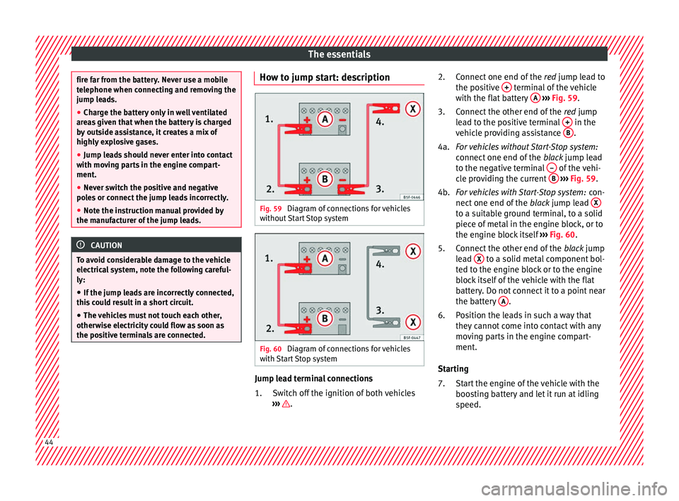
Fig. 59
Diagram of connections for vehicles
w ithout
Start Stop system Fig. 60
Diagram of connections for vehicles
w ith
St
art Stop system Jump lead terminal connections
Swit
c
h off the ignition of both vehicles
››› .
1. Connect one end of the
re
d
jump lead to
the positive + terminal of the vehicle
w ith the fl
at
battery A
› ››
Fig. 59
.
C
onnect the other end of the red jump
lead to the positive terminal + in the
v ehic
l
e providing assistance B .
F or
vehicles without Start-Stop system:
connect one end of the black jump lead
to the negative terminal – of the vehi-
c l
e pr
oviding the current B
› ››
Fig. 59
.
F
or vehicles with Start-Stop system: con-
nect one end of the black jump lead X to a suitable ground terminal, to a solid
piec
e of
met
al in the engine block, or to
the engine block itself ››› Fig. 60.
Connect the other end of the black jump
lead X to a solid metal component bol-
t ed t
o the en
gine block or to the engine
block itself of the vehicle with the flat
battery. Do not connect it to a point near
the battery A .
P o
s
ition the leads in such a way that
they cannot come into contact with any
moving parts in the engine compart-
ment.
Starting Start the engine of the vehicle with the
boosting battery and let it run at idling
speed.
2.
3.
4a.
4b.
5.
6.
7.
44
Page 47 of 232
The essentials
Start the engine of the vehicle with the
fl at
b
attery and wait for 2 or 3 minutes
until the engine is running.
Removing the jump leads Before you remove the jump leads,
switch off the dipped beam headlights if
they are switched on.
Turn on the heater blower and heated
rear window in the vehicle with the flat
battery. This helps minimise voltage
peaks which are generated when the
leads are disconnected.
When the engine is running, disconnect
the leads in reverse order to the details
given above.
Make sure the battery clamps have sufficient
metal-to-metal contact with the battery termi-
nals.
If the engine fails to start after about 10 sec-
onds, switch off the starter and try again after
about 1 minute. WARNING
● Ple a
se note the safety warnings referring to
working in the engine compartment
››› page 187.
● The battery providing assistance must have
the same v
oltage as the flat battery (12V) and
approximately the same capacity (see imprint 8.
9.
10.
11.
on battery). Failure to comply could result in
an exp
lo
sion.
● Never use jump leads when one of the bat-
teries
is frozen. Danger of explosion! Even af-
ter the battery has thawed, battery acid could
leak and cause chemical burns. If a battery
freezes, it should be replaced.
● Keep sparks, flames and lighted cigarettes
awa
y from batteries, danger of explosion.
Failure to comply could result in an explo-
sion.
● Observe the instructions provided by the
manufact
urer of the jump leads.
● Do not connect the negative cable from the
other vehic
le directly to the negative terminal
of the flat battery. The gas emitted from the
battery could be ignited by sparks. Danger of
explosion.
● Never attach the negative cable to fuel sys-
tem component
s or the brake lines in the oth-
er vehicle.
● The non-insulated parts of the battery
clamp
s must not be allowed to touch. The
jump lead attached to the positive battery
terminal must not touch metal parts of the ve-
hicle, this can cause a short circuit.
● Position the leads in such a way that they
cannot c
ome into contact with any moving
parts in the engine compartment.
● Do not lean on the batteries. This could re-
sult
in chemical burns. Note
The vehicles must not touch each other, oth-
erw i
se electricity could flow as soon as the
positive terminals are connected. Changing the wiper blades
Wind s
creen wipers service position Fig. 61
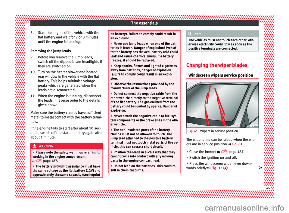
Wipers in service position. The wiper arms can be raised when the wip-
er
s
ar
e in service position ›››
Fig. 61.
● Close the bonnet ›››
page 187.
● Switch the ignition on and off.
● Press the windscreen wiper lever down-
ward
s briefly ›››
Fig. 32 4 .
» 45
Page 48 of 232
The essentials
Before driving, always lower the wiper arms.
When the ignition i s
sw
itched on, the wind-
screen wiper arms return to their initial posi-
tion upon activating the windscreen wiper
lever.
››› page 75 Changing the front wiper blades
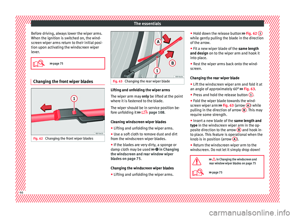
Fig. 62
Changing the front wiper blades Fig. 63
Changing the rear wiper blade Lifting and unfolding the wiper arms
The w
iper arm m
a
y only be lifted at the point
where it is fastened to the blade.
The wiper should be in service position be-
fore unfolding it ›››
page 108.
Cleaning windscreen wiper blades ● Lifting and unfolding the wiper arms.
● Use a soft cloth to remove dust and dirt
from the wind
screen wiper blades.
● If the blades are very dirty, a sponge or
damp cloth m
ay be used ››› in Changing
the w ind
s
creen and rear window wiper
blades on page 75.
Changing the windscreen wiper blades
● Lifting and unfolding the wiper arms. ●
Hold do
wn the release button ››› Fig. 62 1 while gently pulling the blade in the direction
of
the arr
o
w.
● Fit a new wiper blade of the same len
gth
and design on to the wiper arm and hook it
into place.
● Rest the wiper arms back onto the wind-
scr
een.
Changing the rear wiper blade
● Lift the windscreen wiper arm and fold it at
an angle of
approximately 60° ››› Fig. 63.
● Press and hold the release button 1 .
● Fold the wiper blade towards the wind-
s c
r
een wiper arm ››› Fig. 63 (arrow A ) while
p u
l
ling in the direction of arrow B . This may
r equir
e some s
trength.
● Insert a new blade of the same len
gth and
type in the windscreen wiper arm in the op-
posite direction to the arrow B and hook in-
t o p
l
ace. This feature is operational when the
knob is in position (arrow A ).
● Return the windscreen wiper arm to the
w ind
s
creen. Do not let it simply drop down!
››› in Changing the windscreen and
rear window wiper blades on page 75
››› page 75 46
Page 55 of 232

Seat belts
●
Av oid d
amaging the seat belt by jamming it
in the door or the seat mechanism.
● If the fabric or other parts of the seat belt
are dam
aged, the seat belts could break in
the event of an accident or sudden braking.
● Always have damaged seatbelts replaced
immediately
by seat belts approved for the
vehicle in question by SEAT. Seat belts which
have been worn in an accident and stretched
must be replaced by a specialised workshop.
Renewal may be necessary even if there is no
apparent damage. The belt anchorage should
also be checked.
● Never attempt to repair, modify or remove a
seat belt
yourself. All repairs to seat belts, re-
tractors and buckles must be carried out by a
specialised workshop. Warning lamp
Fig. 67
Warning lamp on the instrument pan-
el Fig. 68
Indication of seat belt status in the
re ar se
ats on the instrument panel display
It lights up or flashes on
the instrument panel
Driver's seat belt not
fastened or front
passenger seat belt
not fastened if the
front passenger seat
is occupied.
Fasten seat belts!
Objects on the front
passenger seat.Remove any objects from the
front passenger seat and store
them safely.
On the instrument panel
display
A passenger in the
rear seats has not
fastened their seat
belt, if the seat is oc-
cupied.*
Fasten seat belts!
On the instrument panel
display
A passenger in the rear seats has fastened their seat
belt, if the seat is occupied.* Several warning and control lamps light up
for a f
ew sec
onds when the ignition is switch-
ed on, signalling that the function is being
verified. They will switch off after a few sec-
onds.
An audible warning will be heard if the seat
belts are not fastened as the vehicle drives
off and reaches a speed of more then
25 km/h (15 mph) or if the seat belts are un-
fastened while the vehicle is in motion. The
seat belt warning lamp will also flash.
The warning lamp does not switch off until
the driver and front passenger fasten their
seat belts while the ignition is switched on.
Seat belt status display for rear seats
The seat belt status display on the instru-
ment panel informs the driver, when the igni-
tion is switched on, whether any passengers
in the rear seats have fastened their seat
belts. The symbol indicates that the pas-
senger in this seat has fastened “his or her”
seat belt ›››
Fig. 68.
The seat belt status is displayed for around
30 seconds when a seat belt in the rear seats
is fastened or unfastened. You can switch off
this display by pressing the 0.0 / SET button.
»
53Technical data
Advice
Operation
Emergencies
Safety
Page 62 of 232
Safety
●
Ens ur
e deployed airbags and the system
components involved are immediately re-
placed with new, SEAT-approved components
for the vehicle.
● Have any repairs or modifications carried
out at a s
pecialised workshop. Specialised
workshops have the necessary tools, diag-
nostics equipment, repair information and
qualified personnel.
● Never fit recycled or reused airbag compo-
nents in
your vehicle.
● Never modify the airbag system compo-
nents. WARNING
If the airbags are triggered, a fine dust is pro-
duced. Thi
s is normal and it is not an indica-
tion of fire in the vehicle.
● This fine dust may irritate the skin and eyes
and cause br
eathing difficulties, particularly
in people suffering from or who have suffered
from asthma or other illnesses of the respira-
tory tract. To reduce breathing difficulties,
get out of the vehicle and open and doors and
windows to breath in fresh air.
● Should you touch the dust, wash your
hands
and face using a mild soap and water
before you eat.
● Prevent the dust from affecting the eyes or
open wound
s.
● Rinse your eyes with water if you have dust
in them. WARNING
Solvents cause the surfaces of the airbag
modul e
s to become porous. If an airbag is ac-
cidentally triggered, the detachment of plas-
tic parts could cause serious injury.
● Never clean the dash panel and the surfa-
ces
of the airbag modules with cleaners con-
taining solvents. Description of airbag system
Vehicle safety components
The f
o
l
lowing safety equipment makes up the
vehicle safety design to reduce the risk of se-
vere and fatal injuries. Depending on the ve-
hicle equipment, some equipment may not
be fitted in the vehicle or may not be availa-
ble in some markets.
● Optimised seat belts for all seats.
● Seat belt tension devices for driver and
pas
senger.
● Seat belt force limiters for driver and pas-
senger
.
● Seat belt warning lamp
● Front airbags for driver and passenger.
● Side airbags for driver and passenger.
● Airbag control lamp .
● Control units and sensors. ●
Head r
estraints optimised for rear-end colli-
sion.
● Adjustable steering column.
● If necessary, anchor points for child seats
for the re
ar seats.
● Where applicable, mountings for the child
seat up
per retaining strap.
Situations in which the front and side air-
bags do not deploy:
● If the ignition is switched off during the col-
lision.
● In fr
ontal collisions, when the deceleration
meas
ured by the control unit is too low.
● In minor side collisions.
● In rear collisions.
● In the event of the vehicle overturning.
● When the impact speed is lower than the
refer
ence value set in the control unit.
There is a fault in the system if the control
lamp :
● does not light up when the ignition is
switc
hed on,
● turns off after 4 seconds after the ignition
is sw
itched on,
● turns off and then lights up again after the
ignition is sw
itched on,
● illuminates or flashes while the vehicle is
movin
g.
60
Page 63 of 232
Airbag system
WARNING
● The seat belt
s and airbags can only provide
maximum protection if the occupants are
seated correctly ››› page 48.
● If a fault has occurred in the airbag system,
have the sy
stem checked immediately by a
specialised workshop. Otherwise, during a
frontal collision the system might not trigger
correctly or may fail to trigger at all. Airbag activation
The airbags deploy extremely rapidly, within
thou
s
andths
of a second, to provide addi-
tional protection in the event of an accident.
A fine dust may develop when the airbag de-
ploys. This is normal and it is not an indica-
tion of fire in the vehicle.
The airbag system is only ready to function
when the ignition is on.
In special accidents instances, several air-
bags may activate at the same time.
In the event of minor head-on and side colli-
sions, rear-end collisions, overturning or roll-
over of the vehicle, airbags do not activate.
Activation factors
The conditions that lead to the airbag system
activating in each situation cannot be gener-
alised. Some factors play an important role,
such as the properties of the object the vehi- cle hits (hard/soft), angle of impact, vehicle
speed, etc
.
Deceleration trajectory is key for airbag acti-
vation.
The control unit analyses the collision trajec-
tory and activates the respective restraint
system.
If the deceleration rate is below the prede-
fined reference value in the control unit the
airbags will not be triggered, even though
the accident may cause extensive damage to
the car.
The following airbags are triggered in seri-
ous head-on collisions ● Driver airbag.
● Front passenger front airbag
The fol
lowing airbags are triggered in seri-
ous side-on collisions
● Front side airbag on the side of the acci-
dent.
● Re
ar side airbag on the side of the acci-
dent.
In an acc
ident with airbag activation:
● the interior lights switch on (if the interior
light swit
ch is in the courtesy light position);
● the hazard warning lights switch on;
● all doors are unlocked; ●
the fuel s
upply to the engine is cut.
Airbag safety instructions Front airb
ags Read the additional information carefully
›› ›
page 14. WARNING
The airbag is deployed at high speed in frac-
tions of
a second.
● Always keep the deployment areas of the
front airb
ags vacant.
● Never secure objects to the covers or in the
deployment
area of the airbag modules, e.g.
drink holders or phone supports.
● The deployment space between the front
pas
sengers and the airbags must not in any
case be occupied by other passenger, pets
and objects.
● Never fix any object to the windscreen
above the fr
ont airbag on the front passenger
side.
● Do not alter, cover or stick anything to the
steerin
g wheel hub or the surface of the air-
bag module on the passenger side of the
dash panel. » 61
Technical data
Advice
Operation
Emergencies
Safety
Page 65 of 232
Airbag system
Several warning and control lamps light up
f or a f
ew sec
onds when the ignition is switch-
ed on, signalling that the function is being
verified. They will switch off after a few sec-
onds.
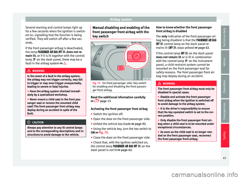
If the front passenger airbag is deactivated,
the lamp does not re-
main lit, or if it is lit together with the control
lamp on the dash panel, there may be a
fault in the airbag system ››› .
WARNING
In the event of a fault in the airbag system,
the airbag m a
y not trigger correctly, may fail
to trigger or may even trigger unexpectedly,
leading to severe or fatal injuries.
● Have the airbag system checked immedi-
ately b
y a specialised workshop.
● Never mount a child seat in the front pas-
senger se
at or remove the mounted child
seat! The front passenger front airbag may
deploy during an accident in spite of the
fault. CAUTION
Always pay attention to any lit control lamps
and to the c orr
esponding descriptions and in-
structions to avoid damage to the vehicle. Manual disabling and enabling of the
fr
ont
p
assenger front airbag with the
key switch Fig. 75
On front passenger side: Key switch
f or en
ab
ling and disabling the front passen-
ger front airbag. Read the additional information carefully
› ›
›
page 15
Activating the front passenger front airbag
● Switch the ignition off.
● Open the door on the front passenger side.
● Unfold the vehicle key blade ›››
page 92.
● Using the vehicle key, turn the key switch to
ON ›››
Fig. 75.
● Close the door on the front passenger side.
● Check that, with the ignition switched on,
the contro
l lamp on the
dash panel is not lit ››› page 62. How to know whether the front passenger
front airb
ag is disabled
The only indication of the front passenger air-
bag being disabled is that the
control lamp on the dash panel re-
mains lit ( stays yellow) ››› page 62.
If the control lamp on the dash panel
does not remain lit or is lit in combination
with the control lamp on the instrument
panel, a child restraint system cannot be
mounted on the front passenger seat for
safety reasons. The front passenger front air-
bag may deploy during an accident. WARNING
The front passenger front airbag must only be
dis ab
led in special cases.
● Disable and activate the front passenger
front airb
ag when the ignition is switched off
to avoid damage to the airbag system.
● It is the driver's responsibility to ensure
that the k
ey operated switch is set to the cor-
rect position.
● Only disable the front passenger front air-
bag when a chi
ld seat is to be mounted under
exceptional circumstances.
● As soon as the child seat is no longer nee-
ded on the front p
assenger seat, reconnect
the front passenger front airbag. 63
Technical data
Advice
Operation
Emergencies
Safety
Page 78 of 232
Emergencies
● Sw it
c
h on the ignition and the hazard warn-
ing lights.
● Release the clutch when both vehicles are
movin
g.
● As soon as the engine starts, press the
clutc
h and move the gear lever into neutral.
This helps to prevent a collision with the tow-
ing vehicle. WARNING
A vehicle with a flat battery should never be
to w
ed.
● Never remove the key from the ignition
lock. Otherw
ise, the steering wheel lock
could suddenly lock. The vehicle would not
be controlled and a serious accident could
ensue. WARNING
When towing the vehicle, the handling and
brak in
g efficiency change considerably.
Please observe the following instructions to
minimise the risk of serious accidents and in-
jury:
● As the driver of the vehicle being towed:
– The brake mu
st be depressed must hard-
er as the brake servo does not operate.
Always remain aware to avoid collision
with the towing vehicle.
– More strength is required at the steering
wheel as the power steering does not op-
erate when the engine is switched off. ●
As the driv er of
the towing vehicle:
– Accelerate gently and carefully.
– Avoid sudden braking and manoeuvres.
– Brake well in advance than usual and
brake gently. CAUTION
● When t ow-
starting, fuel could enter the cat-
alytic converter and damage it.
● Carefully fit and remove the towline anchor-
age and its
cover to avoid damage to the ve-
hicle (e.g. paintwork).
● When towing, fuel could enter the catalytic
conv
erter and cause damage! Note
Fitting a towline anchorage to the rear bump-
er is not
possible. The vehicle is not suitable
for towing other vehicles. Advice for towing the vehicle
Towing vehicles with an automatic gearbox
Not
e the f
o
llowing for a towed vehicle:
● Make sure the gear selector lever is in the N
position.
● Do not
drive faster than 50 km/h (30 mph)
when tow
ing a vehicle.
● Do not tow further than 50 km (30 miles). ●
If a bre
akdown truck is used, the vehicle
must be towed with the front wheels raised.
Situations in which a vehicle should not be
towed
In the following cases, the vehicle should not
be towed but transported on a trailer or spe-
cial vehicle:
● If the vehicle gearbox does not contain lu-
bricant due t
o a fault.
● If the battery is flat and the steering cannot
be unloc
ked as a result, the electronic steer-
ing lock and electronic parking brake cannot
be disengaged.
● If the vehicle to be towed has an automatic
gearbo
x and the distance to be covered is
greater than 50 km (30 miles). Note
The vehicle can only be towed if the steering
lock el
ectronic gearbox lock is deactivated. If
the vehicle has no power supply or there is
an electric system fault, the engine must be
started using jump leads to deactivate the
steering column electronic gearbox lock. 76
Page 80 of 232
Emergencies
CAUTION
When opening and closing in an emergency,
car ef
ully disassemble components and then
reassemble them carefully to avoid damage
to the vehicle. Fuses and bulbs
F u
se
s
Introduction Due to the constant updating of vehicles,
fu
se a
ssignments based on equipment and
the use of the same fuse for various electrical
components, it is not possible to provide an
up-to-date summary of the fuse positions for
the electrical components at the time of
printing this manual. For detailed information
about the fuse positions, please consult a
technical service.
In general, a fuse can be assigned to various
electrical components. Likewise, an electrical
component can be protected by several
fuses.
Only replace fuses when the cause of the
problem has been solved. If a newly inserted
fuse blows after a short time, you must have
the electrical system checked by a special-
ised workshop as soon as possible. WARNING
The high voltages in the electrical system can
give seriou s
electrical shocks, causing burns
and even death!
● Never touch the electrical wiring of the igni-
tion syst
em. ●
Tak e c
are not to cause short circuits in the
electrical system. WARNING
Using unsuitable fuses, repairing fuses or
bridgin g a curr
ent circuit without fuses can
cause a fire and serious injury.
● Never use a fuse with a higher value. Only
repl
ace fuses with a fuse of the same amper-
age (same colour and markings) and size.
● Never repair a fuse.
● Never replace a fuse by a metal strip, staple
or simil
ar. CAUTION
● To pr ev
ent damage to the vehicle's electric
system, before replacing a fuse always turn
off the ignition, the lights and all electrical
elements and remove the key from the igni-
tion.
● If you replace a fuse with higher-rating
fuse,
you could cause damage to another part
of the electrical system.
● Protect the fuse boxes when open to pre-
vent the entr
y of dust or humidity as they can
damage the electrical system. Note
● One component m
ay have more than one
fuse. 78