jack Seat Mii 2017 Owner's manual
[x] Cancel search | Manufacturer: SEAT, Model Year: 2017, Model line: Mii, Model: Seat Mii 2017Pages: 232, PDF Size: 4.91 MB
Page 38 of 232
The essentials
● Sc r
ew the infl
ator tube ››› Fig. 48 3 into
the se al
ant
bottle. The bottle's seal will break
automatically.
● Remove the lid from the filling tube
›››
Fig. 48 3 and screw the open end of the
t ube int
o the ty
re valve.
● With the tyre sealant bottle upside down,
fill
the tyre with the contents of the sealant
bottle.
● Remove the bottle from the valve.
● Place the insert back into the tyre valve us-
ing the too
l ››› Fig. 48 1 .
Infl atin
g the ty
re
● Screw the compressor tyre inflator tube
›››
Fig. 48 5 into the tyre valve.
● Check that the air bleed screw is closed
› ›
›
Fig. 48 7 .
● Start the engine and leave it running.
● Insert the connector ››
›
Fig. 48 9 into the
v ehic
l
e's 12-volt socket ›››
page 120.
● Turn the air compressor on with the ON/OFF
switc
h ››› Fig. 48 8 .
● Keep the air compressor running until it
r e
ac
hes 2.0 to 2.5 bar
(29-36 psi/200-250 kPa). A maximum of 8
minutes.
● Disconnect the air compressor.
● If it does not reach the pressure indicated,
uns
crew the tyre inflator tube from the valve. ●
Move the
vehicle 10m so that the sealant is
distributed throughout the tyre.
● Screw the compressor tyre inflator into the
valve.
● R
epeat the inflation process.
● If the indicated pressure still cannot be
reac
hed, the tyre is too badly damaged. Stop
and request assistance from an authorised
technician.
● Disconnect the air compressor. Unscrew
the tyre infl
ator tube from the tyre valve.
● When the tyre pressure is between 2.5 and
2.0 bars, c
ontinue driving without exceeding
80 km/h (50 mph).
● Check the pressure again after 10 minutes
›››
page 74.
››› in TMS (Tyre Mobility System)* on
page 73
››› page 72 Changing a wheel
V ehic
l
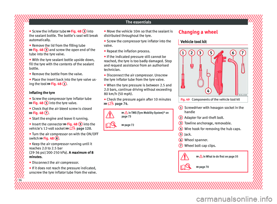
e tool kit Fig. 49
Components of the vehicle tool kit Screwdriver with hexagon socket in the
h
andl
e
Ad
apter for anti-theft bolt.
Towline anchorage, removable.
Wire hook for removing the hub caps.
Jack.
Wheel spanner.
Wheel bolt cap clips.
››› in What to do first on page 35
››› page 70 1
2
3
4
5
6
7
36
Page 40 of 232
The essentials
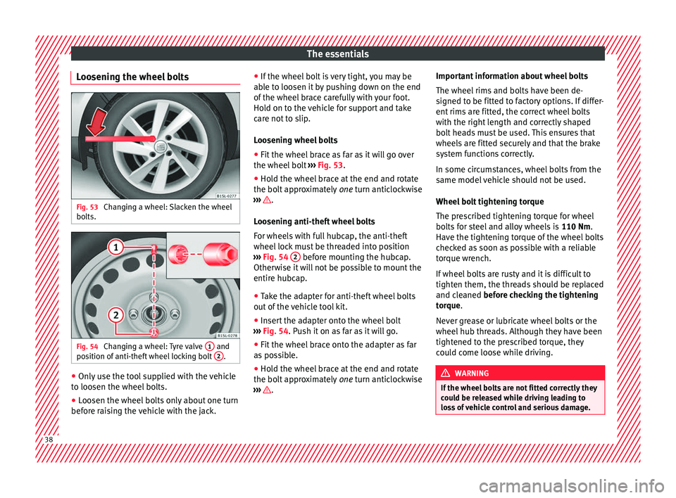
Loosening the wheel bolts Fig. 53
Changing a wheel: Slacken the wheel
bo lts. Fig. 54
Changing a wheel: Tyre valve 1 and
po s
ition of
anti-theft wheel locking bolt 2 .
●
Only use the tool supplied with the vehicle
t o loo
sen the wheel
bolts.
● Loosen the wheel bolts only about one turn
before r
aising the vehicle with the jack. ●
If the wheel bo
lt is very tight, you may be
able to loosen it by pushing down on the end
of the wheel brace carefully with your foot.
Hold on to the vehicle for support and take
care not to slip.
Loosening wheel bolts
● Fit the wheel brace as far as it will go over
the wheel bolt
››› Fig. 53.
● Hold the wheel brace at the end and rotate
the bolt ap
proximately one turn anticlockwise
››› .
L oo
senin
g anti-theft wheel bolts
For wheels with full hubcap, the anti-theft
wheel lock must be threaded into position
››› Fig. 54 2 before mounting the hubcap.
Other w
i
se it will not be possible to mount the
entire hubcap.
● Take the adapter for anti-theft wheel bolts
out of the
vehicle tool kit.
● Insert the adapter onto the wheel bolt
›››
Fig. 54. Push it on as far as it will go.
● Fit the wheel brace onto the adapter as far
as po
ssible.
● Hold the wheel brace at the end and rotate
the bolt ap
proximately one turn anticlockwise
››› .Important information about wheel bolts
The wheel
rims and bo
lts have been de-
signed to be fitted to factory options. If differ-
ent rims are fitted, the correct wheel bolts
with the right length and correctly shaped
bolt heads must be used. This ensures that
wheels are fitted securely and that the brake
system functions correctly.
In some circumstances, wheel bolts from the
same model vehicle should not be used.
Wheel bolt tightening torque
The prescribed tightening torque for wheel
bolts for steel and alloy wheels is 110 Nm.
Have the tightening torque of the wheel bolts
checked as soon as possible with a reliable
torque wrench.
If wheel bolts are rusty and it is difficult to
tighten them, the threads should be replaced
and cleaned before checking the tightening
torque.
Never grease or lubricate wheel bolts or the
wheel hub threads. Although they have been
tightened to the prescribed torque, they
could come loose while driving. WARNING
If the wheel bolts are not fitted correctly they
cou l
d be released while driving leading to
loss of vehicle control and serious damage. 38
Page 41 of 232
The essentials
●
Only u
se wheel bolts which correspond to
the wheel rims in question.
● Never use different wheel bolts.
● The bolts and threads should be clean, free
of oil
and grease and easy to thread.
● To loosen and tighten the wheel bolts, al-
way
s use the wheel brace supplied with the
vehicle.
● Loosen the wheel bolts only about one turn
before r
aising the vehicle with the jack.
● Never grease or lubricate wheel bolts or the
wheel hub thre
ads. Although they have been
tightened to the prescribed torque, they
could come loose while driving.
● Never loosen the bolted joints of wheel
rims with bo
lted ring trims.
● If the wheel bolts are not tightened to the
correct
torque, they may come loose while
driving, and the bolts and rims may come
out. If the tightening torque is too high, the
wheel bolts and threads can be damaged. Raising the vehicle with the jack
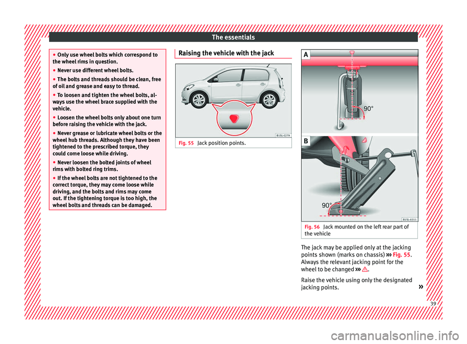
Fig. 55
Jack position points. Fig. 56
Jack mounted on the left rear part of
the v
ehic
le The jack may be applied only at the jacking
points
sho
wn (m
arks on chassis) ››› Fig. 55.
Always the relevant jacking point for the
wheel to be changed ››› .
R ai
se the
vehicle using only the designated
jacking points. » 39
Page 42 of 232
The essentials
WARNING
If the vehicle is not correctly raised, it could
fa l
l off the jack causing serious injury. Please
observe the following rules to minimise the
risk of injury:
● You should only use a jack approved by
SEAT f
or your vehicle. Other jacks, even those
approved for other SEAT models, might slip
out of place.
● The ground should be firm and flat. If the
ground i
s sloped or soft then the vehicle
could slip and fall off the jack. If necessary,
support the jack on a wide solid base.
● If the ground is slippery, such as tiles,
plac
e a non-slip surface (a floor mat, for in-
stance) beneath the jack to avoid slipping.
● Only fit the jack at the prescribed jacking
points. The c
law of the jack should grip the
reinforcement nerve on the underbody
››› Fig. 56.
● You should never place a body limb such as
an arm or leg u
nder a raised vehicle that is
solely supported by the jack.
● If you have to work underneath the vehicle,
you mus
t use suitable stands additionally to
support the vehicle, there is a risk of acci-
dent!.
● Never raise the vehicle if it is tilting to one
side or the engine i
s running.
● Never start the engine when the vehicle is
raised.
The vehicle may come loose from the
jack due to the engine vibrations. Removing and fitting a wheel
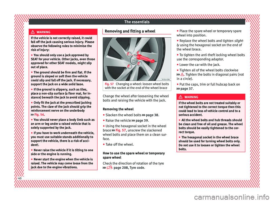
Fig. 57
Changing a wheel: loosen wheel bolts
w ith the soc
k
et at the end of the wheel brace Change the wheel after loosening the wheel
bo
lts
and r
aising the vehicle with the jack.
Removing the wheel
● Slacken the wheel bolts ›››
page 38.
● Raise the vehicle ›››
page 39.
● Using the hexagonal socket in the wheel
brace ›
›› Fig. 57, unscrew the slackened
wheel bolts and place them on a clean sur-
face.
● Take off the wheel.
How to u
se the spare wheel or temporary
spare wheel
Check the direction of rotation of the tyre
››› page 208, Tyre code. ●
Place the s
pare wheel or temporary spare
wheel into position.
● Replace the wheel bolts and tighten slight
-
ly using the hexagonal socket on the end of
the wheel brace.
● To tighten the anti-theft locking wheel bolts
use the corr
esponding adaptor.
● Lower the car with the jack.
● Tighten all of the wheel bolts clockwise
›››
. Tighten the bolts in diagonal pairs (not
in a c ir
c
le).
● Put the caps, trim or full hubcap back on
›››
page 37. WARNING
If the wheel bolts are not treated suitably or
not tight ened t
o the correct torque then this
could lead to loss of vehicle control and to a
serious accident.
● All the wheel bolts and hub threads should
be cle
an and free of oil and grease. The wheel
bolts should be easily tightened to the cor-
rect torque.
● The hexagonal socket in the wheel brace
should be u
sed for turning wheel bolts only.
Do not use it to loosen or tighten the wheel
bolts. 40
Page 73 of 232
Self-help
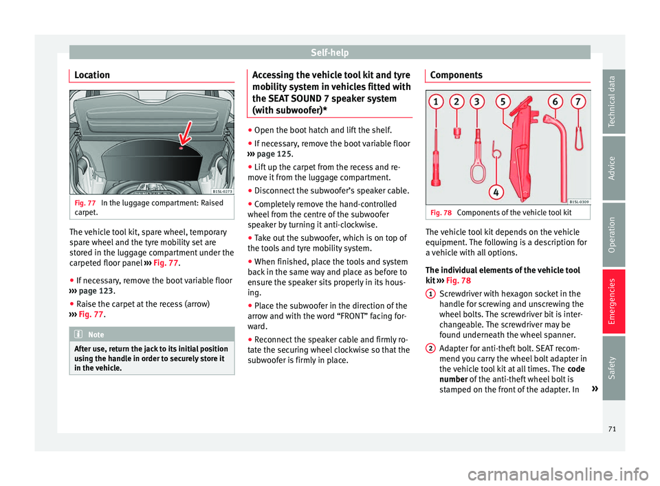
Location Fig. 77
In the luggage compartment: Raised
c arpet
. The vehicle tool kit, spare wheel, temporary
s
p
ar
e wheel and the tyre mobility set are
stored in the luggage compartment under the
carpeted floor panel ›››
Fig. 77.
● If necessary, remove the boot variable floor
›››
page 123.
● Raise the carpet at the recess (arrow)
›››
Fig. 77. Note
After use, return the jack to its initial position
us in
g the handle in order to securely store it
in the vehicle. Accessing the vehicle tool kit and tyre
mo
b
i
lity system in vehicles fitted with
the SEAT SOUND 7 speaker system
(with subwoofer)* ●
Open the boot hatch and lift the shelf.
● If necessary, remove the boot variable floor
›› ›
page 125.
● Lift up the carpet from the recess and re-
move it
from the luggage compartment.
● Disconnect the subwoofer’s speaker cable.
● Completely remove the hand-controlled
wheel fr om the c
entre of the subwoofer
speaker by turning it anti-clockwise.
● Take out the subwoofer, which is on top of
the tool
s and tyre mobility system.
● When finished, place the tools and system
back
in the same way and place as before to
ensure the speaker sits properly in its hous-
ing.
● Place the subwoofer in the direction of the
arrow and w
ith the word “FRONT” facing for-
ward.
● Reconnect the speaker cable and firmly ro-
tate the sec
uring wheel clockwise so that the
subwoofer is firmly in place. Components
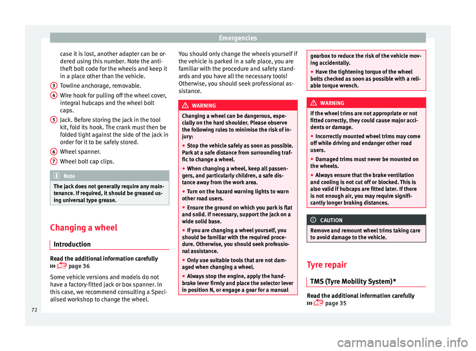
Fig. 78
Components of the vehicle tool kit The vehicle tool kit depends on the vehicle
equipment
.
The f
ollowing is a description for
a vehicle with all options.
The individual elements of the vehicle tool
kit ››› Fig. 78
Screwdriver with hexagon socket in the
handle for screwing and unscrewing the
wheel bolts. The screwdriver bit is inter-
changeable. The screwdriver may be
found underneath the wheel spanner.
Adapter for anti-theft bolt. SEAT recom-
mend you carry the wheel bolt adapter in
the vehicle tool kit at all times. The code
number of the anti-theft wheel bolt is
stamped on the front of the adapter. In »
1 2
71
Technical data
Advice
Operation
Emergencies
Safety
Page 74 of 232
Emergencies
case it is lost, another adapter can be or-
der ed u
s
ing this number. Note the anti-
theft bolt code for the wheels and keep it
in a place other than the vehicle.
Towline anchorage, removable.
Wire hook for pulling off the wheel cover,
integral hubcaps and the wheel bolt
caps.
Jack. Before storing the jack in the tool
kit, fold its hook. The crank must then be
folded tight against the side of the jack in
order for it to be safely stored.
Wheel spanner.
Wheel bolt cap clips. Note
The jack does not generally require any main-
ten anc
e. If required, it should be greased us-
ing universal type grease. Changing a wheel
Intr oduction Read the additional information carefully
› ›
›
page 36
Some vehicle versions and models do not
have a factory-fitted jack or box spanner. In
this case, we recommend consulting a Speci-
alised workshop to change the wheel. 3 4
5
6
7 You should only change the wheels yourself if
the
v
ehic
le is parked in a safe place, you are
familiar with the procedure and safety stand-
ards and you have all the necessary tools!
Otherwise, you should seek professional as-
sistance. WARNING
Changing a wheel can be dangerous, espe-
ci a
lly on the hard shoulder. Please observe
the following rules to minimise the risk of in-
jury:
● Stop the vehicle safely as soon as possible.
Park at
a safe distance from surrounding traf-
fic to change a wheel.
● When changing a wheel, keep all passen-
gers, and p
articularly children, a safe dis-
tance away from the work area.
● Turn on the hazard warning lights to warn
other roa
d users.
● Ensure the ground on which you park is flat
and solid. If nec
essary, support the jack on a
wide solid base.
● If you are changing a wheel yourself, you
should be f
amiliar with the required proce-
dure. Otherwise, you should seek professio-
nal assistance.
● Only use suitable tools that are not dam-
aged when ch
anging a wheel.
● Always stop the engine, apply the hand-
brake l
ever firmly and place the selector lever
in position N, or engage a gear for a manual gearbox to reduce the risk of the vehicle mov-
ing ac
c
identally.
● Have the tightening torque of the wheel
bolts
checked as soon as possible with a reli-
able torque wrench. WARNING
If the wheel trims are not appropriate or not
fitt ed c orr
ectly, they could cause major acci-
dents or damage.
● Incorrectly mounted wheel trims may come
off whil
e driving and endanger other road
users.
● Damaged trims must never be mounted on
the wheels.
● Alw
ays ensure that the brake ventilation
and coolin
g is not cut off or blocked. This is
also valid if hubcaps are fitted later. If there
is not enough air, you may require signifi-
cantly longer braking distances. CAUTION
Remove and remount wheel trims taking care
to av oid d
amage to the vehicle. Tyre repair
TM S (T
yre Mobility System)* Read the additional information carefully
› ›
›
page 35
72
Page 75 of 232
Self-help
The Anti-puncture kit* (Tyre Mobility System)
w i
l
l reliably seal punctures caused by the
penetration of a foreign body of up to about
4 mm in diameter. Do not remove foreign ob-
jects, e.g. screws or nails, from the tyre.
After inserting the sealant residue in the tyre,
you must again check the tyre pressure about
10 minutes after starting the engine.
You should only use the tyre mobility set if
the vehicle is parked in a safe place, you are
familiar with the procedure and you have the
necessary tyre mobility set! Otherwise, you
should seek professional assistance.
Do not use the tyre sealant in the following
cases:
● If the wheel rim has been damaged.
● In outside temperatures below -20°C (-4°F).
● In the event of cuts or perforations in the
tyre gr
eater than 4 mm.
● If you have been driving with very low pres-
sure or a c
ompletely flat tyre.
● If the sealant bottle has passed its use by
date. WARNING
Using the tyre mobility system can be dan-
ger ou
s, especially when filling the tyre at the
roadside. Please observe the following rules
to minimise the risk of injury: ●
Stop the v
ehicle safely as soon as possible.
Park it at a safe distance from surrounding
traffic to fill the tyre.
● Ensure the ground on which you park is flat
and solid.
● Al
l passengers and particularly children
must
keep a safe distance from the work area.
● Turn on the hazard warning lights to warn
other roa
d users.
● Use the tyre mobility system only if you are
famili
ar with the necessary procedures. Oth-
erwise, you should seek professional assis-
tance.
● The tyre mobility set is intended for tempo-
rary
emergency use only until you can reach
the nearest specialised workshop.
● Replace the repaired tyre with the tyre mo-
bility
set as soon as possible.
● The sealant is a health hazard and must be
cle
aned immediately if it comes into contact
with the skin.
● Always keep the tyre mobility set out of the
reac
h of small children.
● Never use an equivalent jack, even if it has
been appro
ved for your vehicle.
● Always stop the engine, apply the hand-
brake l
ever firmly and engage gear if using a
manual gearbox, in order to reduce the risk of
vehicle involuntary movement. WARNING
A tyre filled with sealant does not have the
same per f
ormance properties as a conven-
tional tyre.
● Never drive faster than 80 km/h (50 mph).
● Avoid heavy acceleration, hard braking and
fas
t cornering.
● Drive for only 10 minutes at a maximum
speed of 80
km/h (50 mph) and then check
the tyre. For the sake of the environment
Dispose of used or expired sealant observing
any l
egal requirements. Note
● A new bottle of se
alant can be purchased at
SEAT dealerships.
● Take into account the separate instruction
manual
of the tyre mobility set* manufactur-
er. 73
Technical data
Advice
Operation
Emergencies
Safety
Page 171 of 232

Care and maintenance
●
Whil e driv
ing, the mobile telephone, other
equipment including telephone accessories
such as telephone supports, notepads and
navigators must be correctly secured, away
from the airbags deployment zones, or stored
in a safe place. WARNING
When using a mobile telephone or two-way
r a dio w
ithout connecting an external aerial,
the maximum permitted levels of electromag-
netic radiation in the vehicle may be excee-
ded, thus putting the driver and the rest of
the vehicle occupants in danger. This is also
the case if the aerial has not been correctly
installed.
● A minimum of 20 centimetres should be
kept betw
een mobile phone aerials and artifi-
cial pacemakers, as mobile telephones may
affect the working of pacemakers.
● Do not keep mobile phones in breast pock-
ets dir
ectly above pacemakers.
● Immediately switch off the mobile tele-
phone if y
ou suspect any interference with
pacemakers or other types of medical equip-
ment. Support points for raising the vehicle
Fig. 159
Front jacking points for raising vehi-
c l
e w
ith lifting platform or jack Fig. 160
Rear jacking points for raising vehi-
c l
e w
ith lifting platform or jack Always use the jacking points indicated in
the figur
e
s
››› Fig. 159 and ››› Fig. 160 when
raising the vehicle. If the vehicle is not lifted
at these points, it could be seriously dam-
aged ››› or lead to serious injury
›
››
.The vehicle should not be lifted using lifting
p
latf
orms with lift pads containing fluid.
When raising a vehicle using a platform or
jack, a series of precautionary measures are
required. Do not raise the vehicle with a lift-
ing platform or jack unless you have received
training in how to do so and know how to do
so safely.
Notes on raising the vehicle with a jack
››› page 72. WARNING
The improper use of the lifting platform or
the jac k
when raising the vehicle may result
in accidents or serious injury.
● Before raising the vehicle, please observe
the manufact
urer's instructions for the plat-
form or jack, and the legal requirements,
where applicable.
● There should not be anyone inside the ve-
hicle when it
is being raised or once it is in
the air.
● Only use the jacking points indicated in the
figures
››› Fig. 159 and ››› Fig. 160 when rais-
ing the vehicle. If the vehicle is not lifted at
the indicated points, it may fall from the plat-
form while the engine or gearbox is being
dismounted, for example.
● The jacking points should be centrally
aligned and firmly
positioned on the platform
support plates. » 169
Technical data
Advice
Operation
Emergencies
Safety
Page 189 of 232
Checking and refilling levels
●
Noise s
heard when refuelling are normal
and do not indicate the presence of a fault in
the system.
● The vehicle natural gas system is prepared
both for ref
uelling with a small compressor
(slow refuel) and a large compressor (fast re-
fuel) in natural gas service stations. Bonnet
Work in
g in the engine compartment Read the additional information carefully
› ›
›
page 10
Before working in the engine compartment,
make sure that the vehicle is parked on hori-
zontal and firm ground.
The engine compartment of the vehicle is a
hazardous area. Never work on the engine or
in the engine compartment if you are not fa-
miliar with the operations to be carried out,
the applicable safety standards and especial-
ly if you do not have the necessary instru-
ments, liquids and tools ››› ! If required,
h av
e an
y work carried out by a specialised
workshop. Negligent work can cause serious
injury. WARNING
If the vehicle moves unexpectedly, this could
cau se seriou
s injury. ●
Never w ork
under the vehicle if it has not
been immobilized. If you must work under-
neath the vehicle with the wheels in contact
with the ground then it should be parked on
flat ground, the wheels should be prevented
from moving and the key should be removed
from the ignition.
● If you have to work underneath the vehicle,
you mus
t use suitable stands additionally to
support the vehicle, there is a risk of acci-
dent!. The jack is not intended for this kind of
work and its failure could lead to severe inju-
ries.
● Disconnect the Start-Stop system. WARNING
The engine compartment is a dangerous area
cap ab
le of causing serious injury.
● For all type of work, always take the utmost
precaution
s, work carefully and note the gen-
eral safety standards in force. Never take per-
sonal risks.
● Never work on the engine or in the engine
compar
tment if you are not familiar with the
necessary operations. If you are not sure
about procedures then visit a specialised
workshop to carry out the necessary work.
Working incorrectly can cause serious inju-
ries.
● Never open the bonnet if you see steam or
cool
ant escaping from the engine compart-
ment. This may cause serious burns. Always
wait until you cannot see or hear the sound of steam or coolant coming from the engine
comp
ar
tment.
● Always allow the engine to cool down be-
fore openin
g the bonnet.
● Contact with hot elements of the engine
and the exhau
st system can cause burns.
● Once the engine has cooled, follow the in-
structions
below before opening the bonnet:
– Engage the handbrake and place the gear
selector lever in N or the gear stick in
neutral.
– Remove the key from the ignition.
– Keep children away from the engine com-
partment and never leave them unsuper-
vised.
● When the engine is warm or hot, the cool-
ing sys
tem is pressurised. Do not unscrew
the cap on the expansion tank when the en-
gine is hot. Otherwise, coolant may spray out
under pressure causing burns and serious in-
jury.
– After cooling, carefully and slowly un-
screw the cap anticlockwise, gently
pressing down on it.
– Always protect your face, hands and arms
from hot coolant and steam using a large,
thick cloth.
● When refilling liquids, avoid spilling them
on part
s of the engine and the exhaust sys-
tem. Spilled liquids could cause a fire. » 187
Technical data
Advice
Operation
Emergencies
Safety
Page 226 of 232
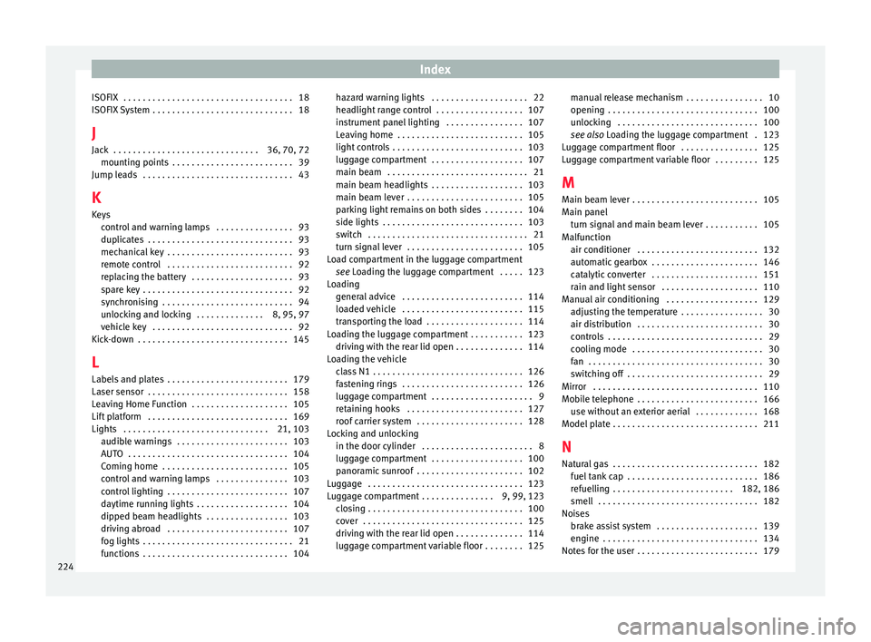
Index
ISOFIX . . . . . . . . . . . . . . . . . . . . . . . . . . . . . . . . . . . 18
ISOFIX
S
ystem . . . . . . . . . . . . . . . . . . . . . . . . . . . . . 18
J Jack . . . . . . . . . . . . . . . . . . . . . . . . . . . . . . 36, 70, 72 mounting points . . . . . . . . . . . . . . . . . . . . . . . . . 39
Jump leads . . . . . . . . . . . . . . . . . . . . . . . . . . . . . . . 43
K
Keys control and warning lamps . . . . . . . . . . . . . . . . 93
duplicates . . . . . . . . . . . . . . . . . . . . . . . . . . . . . . 93
mechanical key . . . . . . . . . . . . . . . . . . . . . . . . . . 93
remote control . . . . . . . . . . . . . . . . . . . . . . . . . . 92
replacing the battery . . . . . . . . . . . . . . . . . . . . . 93
spare key . . . . . . . . . . . . . . . . . . . . . . . . . . . . . . . 92
synchronising . . . . . . . . . . . . . . . . . . . . . . . . . . . 94
unlocking and locking . . . . . . . . . . . . . . 8, 95, 97
vehicle key . . . . . . . . . . . . . . . . . . . . . . . . . . . . . 92
Kick-down . . . . . . . . . . . . . . . . . . . . . . . . . . . . . . . 145
L
Labels and plates . . . . . . . . . . . . . . . . . . . . . . . . . 179
Laser sensor . . . . . . . . . . . . . . . . . . . . . . . . . . . . . 158
Leaving Home Function . . . . . . . . . . . . . . . . . . . . 105
Lift platform . . . . . . . . . . . . . . . . . . . . . . . . . . . . . 169
Lights . . . . . . . . . . . . . . . . . . . . . . . . . . . . . . 21, 103 audible warnings . . . . . . . . . . . . . . . . . . . . . . . 103
AUTO . . . . . . . . . . . . . . . . . . . . . . . . . . . . . . . . . 104
Coming home . . . . . . . . . . . . . . . . . . . . . . . . . . 105
control and warning lamps . . . . . . . . . . . . . . . 103
control lighting . . . . . . . . . . . . . . . . . . . . . . . . . 107
daytime running lights . . . . . . . . . . . . . . . . . . . 104
dipped beam headlights . . . . . . . . . . . . . . . . . 103
driving abroad . . . . . . . . . . . . . . . . . . . . . . . . . 107
fog lights . . . . . . . . . . . . . . . . . . . . . . . . . . . . . . . 21
functions . . . . . . . . . . . . . . . . . . . . . . . . . . . . . . 104 hazard warning lights . . . . . . . . . . . . . . . . . . . . 22
headlight
range control . . . . . . . . . . . . . . . . . . 107
instrument panel lighting . . . . . . . . . . . . . . . . 107
Leaving home . . . . . . . . . . . . . . . . . . . . . . . . . . 105
light controls . . . . . . . . . . . . . . . . . . . . . . . . . . . 103
luggage compartment . . . . . . . . . . . . . . . . . . . 107
main beam . . . . . . . . . . . . . . . . . . . . . . . . . . . . . 21
main beam headlights . . . . . . . . . . . . . . . . . . . 103
main beam lever . . . . . . . . . . . . . . . . . . . . . . . . 105
parking light remains on both sides . . . . . . . . 104
side lights . . . . . . . . . . . . . . . . . . . . . . . . . . . . . 103
switch . . . . . . . . . . . . . . . . . . . . . . . . . . . . . . . . . 21
turn signal lever . . . . . . . . . . . . . . . . . . . . . . . . 105
Load compartment in the luggage compartment see Loading the luggage compartment . . . . . 123
Loading general advice . . . . . . . . . . . . . . . . . . . . . . . . . 114
loaded vehicle . . . . . . . . . . . . . . . . . . . . . . . . . 115
transporting the load . . . . . . . . . . . . . . . . . . . . 114
Loading the luggage compartment . . . . . . . . . . . 123 driving with the rear lid open . . . . . . . . . . . . . . 114
Loading the vehicle class N1 . . . . . . . . . . . . . . . . . . . . . . . . . . . . . . . 126
fastening rings . . . . . . . . . . . . . . . . . . . . . . . . . 126
luggage compartment . . . . . . . . . . . . . . . . . . . . . 9
retaining hooks . . . . . . . . . . . . . . . . . . . . . . . . 127
roof carrier system . . . . . . . . . . . . . . . . . . . . . . 128
Locking and unlocking in the door cylinder . . . . . . . . . . . . . . . . . . . . . . . 8
luggage compartment . . . . . . . . . . . . . . . . . . . 100
panoramic sunroof . . . . . . . . . . . . . . . . . . . . . . 102
Luggage . . . . . . . . . . . . . . . . . . . . . . . . . . . . . . . . 123
Luggage compartment . . . . . . . . . . . . . . . 9, 99, 123 closing . . . . . . . . . . . . . . . . . . . . . . . . . . . . . . . . 100
cover . . . . . . . . . . . . . . . . . . . . . . . . . . . . . . . . . 125
driving with the rear lid open . . . . . . . . . . . . . . 114
luggage compartment variable floor . . . . . . . . 125 manual release mechanism . . . . . . . . . . . . . . . . 10
opening . . . . . . . . . . . . . . . . . . . . . . . . . . . . . . .
100
unlocking . . . . . . . . . . . . . . . . . . . . . . . . . . . . . 100
see also Loading the luggage compartment . 123
Luggage compartment floor . . . . . . . . . . . . . . . . 125
Luggage compartment variable floor . . . . . . . . . 125
M Main beam lever . . . . . . . . . . . . . . . . . . . . . . . . . . 105
Main panel turn signal and main beam lever . . . . . . . . . . . 105
Malfunction air conditioner . . . . . . . . . . . . . . . . . . . . . . . . . 132
automatic gearbox . . . . . . . . . . . . . . . . . . . . . . 146
catalytic converter . . . . . . . . . . . . . . . . . . . . . . 151
rain and light sensor . . . . . . . . . . . . . . . . . . . . 110
Manual air conditioning . . . . . . . . . . . . . . . . . . . 129 adjusting the temperature . . . . . . . . . . . . . . . . . 30
air distribution . . . . . . . . . . . . . . . . . . . . . . . . . . 30
controls . . . . . . . . . . . . . . . . . . . . . . . . . . . . . . . . 29
cooling mode . . . . . . . . . . . . . . . . . . . . . . . . . . . 30
fan . . . . . . . . . . . . . . . . . . . . . . . . . . . . . . . . . . . . 30
switching off . . . . . . . . . . . . . . . . . . . . . . . . . . . . 29
Mirror . . . . . . . . . . . . . . . . . . . . . . . . . . . . . . . . . . 110
Mobile telephone . . . . . . . . . . . . . . . . . . . . . . . . . 166 use without an exterior aerial . . . . . . . . . . . . . 168
Model plate . . . . . . . . . . . . . . . . . . . . . . . . . . . . . . 211
N
Natural gas . . . . . . . . . . . . . . . . . . . . . . . . . . . . . . 182 fuel tank cap . . . . . . . . . . . . . . . . . . . . . . . . . . . 186
refuelling . . . . . . . . . . . . . . . . . . . . . . . . . 182, 186
smell . . . . . . . . . . . . . . . . . . . . . . . . . . . . . . . . . 182
Noises brake assist system . . . . . . . . . . . . . . . . . . . . . 139
engine . . . . . . . . . . . . . . . . . . . . . . . . . . . . . . . . 134
Notes for the user . . . . . . . . . . . . . . . . . . . . . . . . . 179
224