key Seat Mii 2017 Owner's manual
[x] Cancel search | Manufacturer: SEAT, Model Year: 2017, Model line: Mii, Model: Seat Mii 2017Pages: 232, PDF Size: 4.91 MB
Page 5 of 232
Table of Contents
Table of Contents
The e s
senti
als . . . . . . . . . . . . . . . . . . . . . . . . 5
Exterior view . . . . . . . . . . . . . . . . . . . . . . . . . . . . 5
Exterior view . . . . . . . . . . . . . . . . . . . . . . . . . . . . 6
Interior view (left guide) . . . . . . . . . . . . . . . . . . 7
How it works . . . . . . . . . . . . . . . . . . . . . . . . . . . . 8
Unlocking and locking . . . . . . . . . . . . . . . . . . . . 8
Before driving . . . . . . . . . . . . . . . . . . . . . . . . . . . 12
Airbags . . . . . . . . . . . . . . . . . . . . . . . . . . . . . . . . 14
Child seats . . . . . . . . . . . . . . . . . . . . . . . . . . . . . 16
Starting the vehicle . . . . . . . . . . . . . . . . . . . . . . 20
Lights and visibility . . . . . . . . . . . . . . . . . . . . . . 21
SEAT information system . . . . . . . . . . . . . . . . . . 23
Cruise control . . . . . . . . . . . . . . . . . . . . . . . . . . . 24
Warning lamps . . . . . . . . . . . . . . . . . . . . . . . . . . 25
Gearbox lever . . . . . . . . . . . . . . . . . . . . . . . . . . . 26
Air conditioning . . . . . . . . . . . . . . . . . . . . . . . . . 28
Fluid Level control . . . . . . . . . . . . . . . . . . . . . . . 31
Emergencies . . . . . . . . . . . . . . . . . . . . . . . . . . . . 34
Fuses . . . . . . . . . . . . . . . . . . . . . . . . . . . . . . . . . . 34
Bulbs . . . . . . . . . . . . . . . . . . . . . . . . . . . . . . . . . . 35
Action in the event of a puncture . . . . . . . . . . . 35
Changing a wheel . . . . . . . . . . . . . . . . . . . . . . . 36
Snow chains . . . . . . . . . . . . . . . . . . . . . . . . . . . . 41
Emergency towing of the vehicle . . . . . . . . . . . 42
How to jump start . . . . . . . . . . . . . . . . . . . . . . . . 43
Changing the wiper blades . . . . . . . . . . . . . . . . 45
Safety . . . . . . . . . . . . . . . . . . . . . . . . . . . . . . . . 47
Safe driving . . . . . . . . . . . . . . . . . . . . . . . . . . . . 47
Safety first! . . . . . . . . . . . . . . . . . . . . . . . . . . . . . 47
Driving advice . . . . . . . . . . . . . . . . . . . . . . . . . . . 47
Correct position of the vehicle occupants . . . . 48
Pedal area . . . . . . . . . . . . . . . . . . . . . . . . . . . . . . 51 Seat belts
. . . . . . . . . . . . . . . . . . . . . . . . . . . . . . 52
Why wear a set belt . . . . . . . . . . . . . . . . . . . . . . 52
How to properly adjust your seatbelt . . . . . . . . 56
Seat belt tensioners . . . . . . . . . . . . . . . . . . . . . . 57
Airbag system . . . . . . . . . . . . . . . . . . . . . . . . . . 58
Brief introduction . . . . . . . . . . . . . . . . . . . . . . . . 58
Airbag safety instructions . . . . . . . . . . . . . . . . . 61
Deactivating airbags . . . . . . . . . . . . . . . . . . . . . 62
Transporting children safely . . . . . . . . . . . . . . . 64
Safety for children . . . . . . . . . . . . . . . . . . . . . . . 64
Child seats . . . . . . . . . . . . . . . . . . . . . . . . . . . . . 65
Emergencies . . . . . . . . . . . . . . . . . . . . . . . . . . 70
Self-help . . . . . . . . . . . . . . . . . . . . . . . . . . . . . . . 70
In case of emergency . . . . . . . . . . . . . . . . . . . . . 70
Vehicle tool kit* . . . . . . . . . . . . . . . . . . . . . . . . . 70
Changing a wheel . . . . . . . . . . . . . . . . . . . . . . . 72
Tyre repair . . . . . . . . . . . . . . . . . . . . . . . . . . . . . . 72
Changing the windscreen wiper blades . . . . . . 75
Tow-starting and towing . . . . . . . . . . . . . . . . . . 75
Emergency locking and unlocking . . . . . . . . . . 77
Fuses and bulbs . . . . . . . . . . . . . . . . . . . . . . . . . 78
Fuses . . . . . . . . . . . . . . . . . . . . . . . . . . . . . . . . . . 78
Changing bulbs . . . . . . . . . . . . . . . . . . . . . . . . . 79
Operation . . . . . . . . . . . . . . . . . . . . . . . . . . . . . 87
General instrument panel . . . . . . . . . . . . . . . . . 87
Instrument panel . . . . . . . . . . . . . . . . . . . . . . . . 86
Instruments . . . . . . . . . . . . . . . . . . . . . . . . . . . . 88
Opening and closing . . . . . . . . . . . . . . . . . . . . . 92
Vehicle key set . . . . . . . . . . . . . . . . . . . . . . . . . . 92
Central locking* and locking system . . . . . . . . 94
Doors . . . . . . . . . . . . . . . . . . . . . . . . . . . . . . . . . . 98
Rear lid . . . . . . . . . . . . . . . . . . . . . . . . . . . . . . . . 99
Controls for the windows . . . . . . . . . . . . . . . . . . 101
Sliding/tilting electric panoramic sunroof . . . . 102 Lights and visibility
. . . . . . . . . . . . . . . . . . . . . . 103
Lights . . . . . . . . . . . . . . . . . . . . . . . . . . . . . . . . . 103
Visibility . . . . . . . . . . . . . . . . . . . . . . . . . . . . . . . 108
Windscreen wiper and window wiper sys-
tems . . . . . . . . . . . . . . . . . . . . . . . . . . . . . . . . . . 108
Mirr
or . . . . . . . . . . . . . . . . . . . . . . . . . . . . . . . . . 110
Seats and head restraints . . . . . . . . . . . . . . . . . 112
Adjusting the seat and head restraints . . . . . . 112
Seat functions . . . . . . . . . . . . . . . . . . . . . . . . . . 113
Transport and practical equipment . . . . . . . . . 114
Transporting objects . . . . . . . . . . . . . . . . . . . . . 114
Practical equipment . . . . . . . . . . . . . . . . . . . . . . 115
Luggage compartment . . . . . . . . . . . . . . . . . . . . 123
Roof carrier . . . . . . . . . . . . . . . . . . . . . . . . . . . . . 127
Air conditioning . . . . . . . . . . . . . . . . . . . . . . . . . 129
Heating, ventilation and air conditioning . . . . . 129
Driving . . . . . . . . . . . . . . . . . . . . . . . . . . . . . . . . 133
Stopping and starting the engine . . . . . . . . . . . 133
Braking and parking . . . . . . . . . . . . . . . . . . . . . 135
Changing gear . . . . . . . . . . . . . . . . . . . . . . . . . . 142
Steering . . . . . . . . . . . . . . . . . . . . . . . . . . . . . . . 147
Run-in and economical driving . . . . . . . . . . . . . 148
Engine management and exhaust gas purifica-
tion syst
em . . . . . . . . . . . . . . . . . . . . . . . . . . . . . 151
Driving tips . . . . . . . . . . . . . . . . . . . . . . . . . . . . . 152
Driver assistance systems . . . . . . . . . . . . . . . . . 153
Parking distance warning system* . . . . . . . . . . 153
Cruise control* (Cruise control system -
CCS)
. . . . . . . . . . . . . . . . . . . . . . . . . . . . . . . . . . . 155
Safety Assist* (City Safety Assist function) . . . . 156
Hill driving assistant* . . . . . . . . . . . . . . . . . . . . 160
Start-Stop System . . . . . . . . . . . . . . . . . . . . . . . . 160
Towing bracket device . . . . . . . . . . . . . . . . . . . . 163
Driving with a trailer . . . . . . . . . . . . . . . . . . . . . . 163
3
Page 10 of 232
The essentials
How it works
Un loc
k
ing and locking
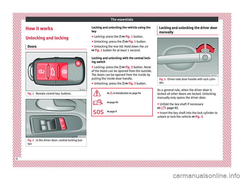
Doors Fig. 1
Remote control key: buttons. Fig. 2
In the driver door: central locking but-
t on Locking and unlocking the vehicle using the
k
ey
â Loc
king: press the ï½ âºâºâº
Fig. 1 button.
â Unlocking: press the ï¼ âºâºâº
Fig. 1 button.
â Unlocking the rear lid: Hold down the ï²
âºâºâº
Fig. 1 button for at least 1 second.
Locking and unlocking with the central lock-
ing switch
â Locking: press the ï½ âºâºâº
Fig. 2 button. None
of the doors can be opened from the outside.
The doors can be opened from the inside by
pulling the inside door handle.
â Unlocking: press the ï¼ âºâºâº
Fig. 2 button.
ïª
âºâºâº in Introduction on page 94
ï©âºâºâº page 94
ïªâºâºâº page 9 Locking and unlocking the driver door
m
anua
l
ly Fig. 3
Driver-side door handle with lock cylin-
der . As a general rule, when the driver door is
loc
k
ed al
l other doors are locked. Unlocking
manually only opens the driver door.
â Unfold the key shaft if necessary
âºâºâº
ï© page 92.
â Insert the key shaft into the lock cylinder to
unloc
k or lock the vehicle âºâºâº Fig. 3.8
Page 11 of 232
The essentials
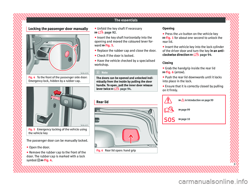
Locking the passenger door manually Fig. 4
To the front of the passenger side door:
Emer g
ency
lock, hidden by a rubber cap. Fig. 5
Emergency locking of the vehicle using
the v
ehic
le key The passenger door can be manually locked.
â Open the door.
â Remove the rubber cap to the front of the
door .
The rubber c
ap is marked with a lock
symbol ï§
âºâºâº Fig. 4. â
Unfol
d the key shaft if necessary
âºâºâº ï© page 92.
â Insert the key shaft horizontally into the
opening and mov
ed the coloured lever for-
ward âºâºâº Fig. 5.
â Replace the rubber cap and close the door.
â Check if the door is locked.
â Have the vehicle checked by a specialised
workshop
. Note
The doors can be opened and unlocked indi-
vidua l
ly from the inside by pulling the door
handle. To open, pull the inner door release
lever twice âºâºâº
ï© page 94. Rear lid
Fig. 6
Rear lid open: hand grip Opening
â Press the ï² b
utton on the
vehicle key
âºâºâº Fig. 1 for about one second to unlock the
rear lid.
â Insert the vehicle key into the lock cylinder
of the driver door and t
urn the key in an anti-
clockwise direction âºâºâº
ï© page 94.
Closing â Grab the handgrip inside the rear lid
âºâºâº
Fig. 6 (arrow).
â Push the rear lid downwards until it locks
into pl
ace in the lock.
â Ensure that it is correctly closed by pulling
on it firmly
.
ïª
âºâºâº in Introduction on page 99
ï©âºâºâº page 99
ïªâºâºâº page 10 9
Page 12 of 232
The essentials
Manual release mechanism for the
r e
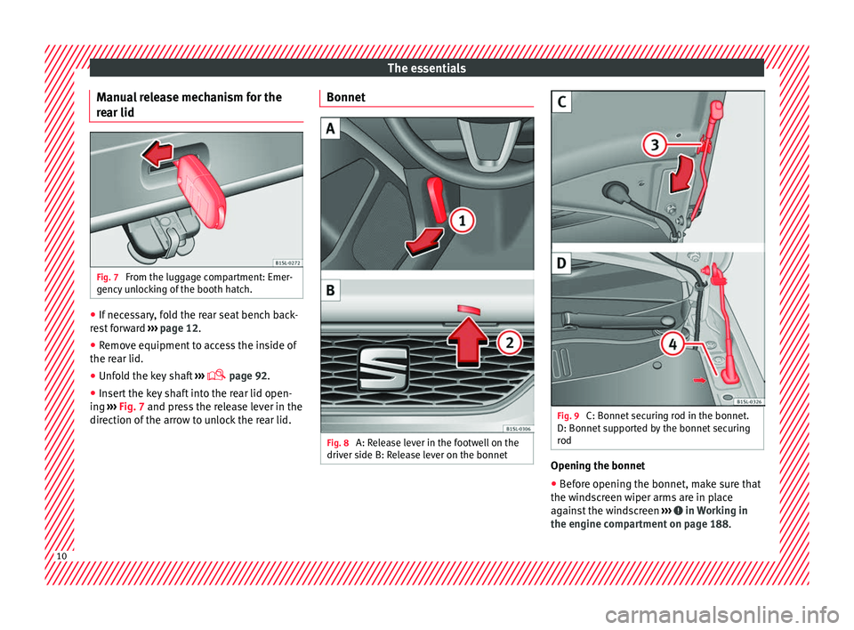
ar lid Fig. 7
From the luggage compartment: Emer-
g ency
u
nlocking of the booth hatch. â
If necessary, fold the rear seat bench back-
r e
s
t forward âºâºâº page 12.
â Remove equipment to access the inside of
the rear lid.
â Unf
old the key shaft âºâºâº
ï© page 92.
â Insert the key shaft into the rear lid open-
ing âºâº
⺠Fig. 7 and press the release lever in the
direction of the arrow to unlock the rear lid. Bonnet
Fig. 8
A: Release lever in the footwell on the
driv er side B: R
elease lever on the bonnet Fig. 9
C: Bonnet securing rod in the bonnet.
D: Bonnet s
up
ported by the bonnet securing
rod Opening the bonnet
â Before opening the bonnet, make sure that
the w ind
s
creen wiper arms are in place
against the windscreen âºâºâº in Working in
the en gine c
omp
artment on page 188. 10
Page 17 of 232
The essentials
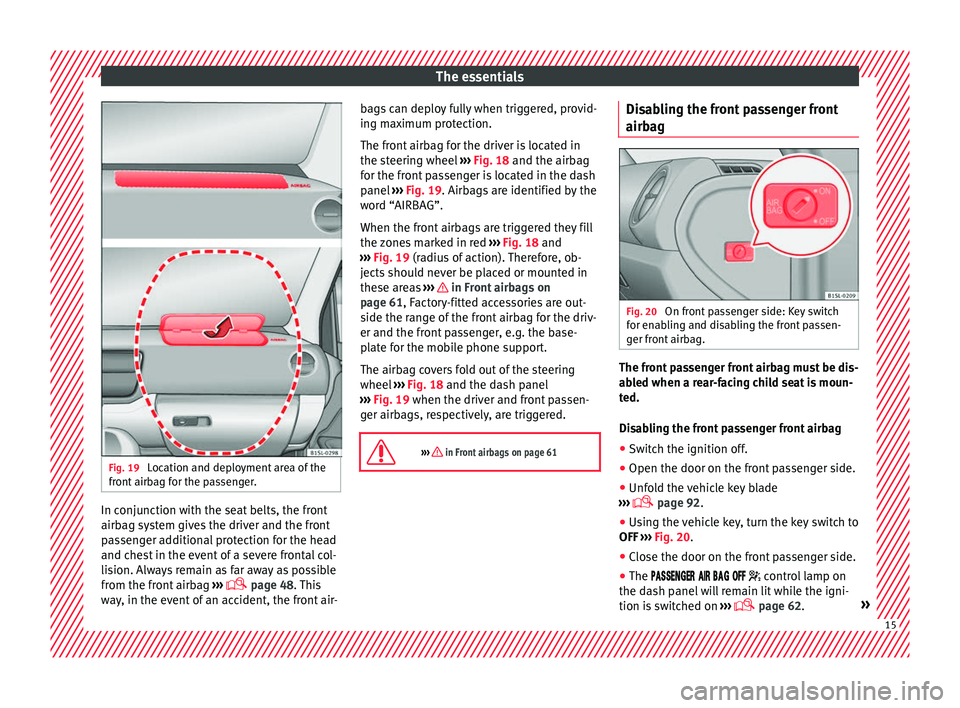
Fig. 19
Location and deployment area of the
fr ont
airb
ag for the passenger. In conjunction with the seat belts, the front
airb
ag sy
s
tem gives the driver and the front
passenger additional protection for the head
and chest in the event of a severe frontal col-
lision. Always remain as far away as possible
from the front airbag âºâºâº
ï© page 48. This
way, in the event of an accident, the front air- bags can deploy fully when triggered, provid-
ing max
imum protection.
The front airbag for the driver is located in
the steering wheel âºâºâº Fig. 18 and the airbag
for the front passenger is located in the dash
panel âºâºâº Fig. 19. Airbags are identified by the
word âAIRBAGâ.
When the front airbags are triggered they fill
the zones marked in red âºâºâº Fig. 18 and
âºâºâº Fig. 19 (radius of action). Therefore, ob-
jects should never be placed or mounted in
these areas âºâºâº in Front airbags on
p ag
e 61
, Factory-fitted accessories are out-
side the range of the front airbag for the driv-
er and the front passenger, e.g. the base-
plate for the mobile phone support.
The airbag covers fold out of the steering
wheel âºâºâº Fig. 18 and the dash panel
âºâºâº Fig. 19 when the driver and front passen-
ger airbags, respectively, are triggered.
ïª
âºâºâº in Front airbags on page 61 Disabling the front passenger front
airb
ag Fig. 20
On front passenger side: Key switch
f or en
ab
ling and disabling the front passen-
ger front airbag. The front passenger front airbag must be dis-
ab
l
ed when a r
ear-facing child seat is moun-
ted.
Disabling the front passenger front airbag
â Switch the ignition off.
â Open the door on the front passenger side.
â Unfold the vehicle key blade
âºâºâº
ï© page 92.
â Using the vehicle key, turn the key switch to
OFF âºâºâº
Fig. 20.
â Close the door on the front passenger side.
â The ïïïïï
ïïï
ï ïïï ïïï
ïïï ï¹ control lamp on
the dash panel will remain lit while the igni-
tion is switched on âºâºâº
ï© page 62. » 15
Page 18 of 232
The essentials
ïªâºâºâº in Manual disabling and enabling of
the front passenger front airbag with the
key switch on page 63
ï©âºâºâº page 62 Side airbags
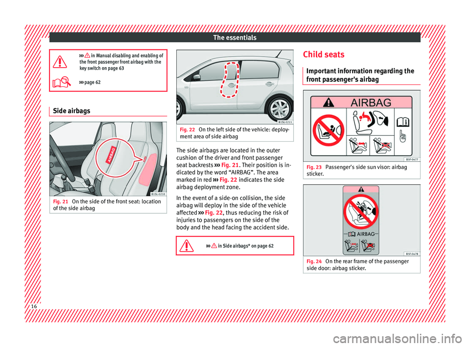
Fig. 21
On the side of the front seat: location
of the s
ide airb
ag Fig. 22
On the left side of the vehicle: deploy-
ment ar e
a of side airbag The side airbags are located in the outer
c
u
shion of
the driver and front passenger
seat backrests âºâºâº Fig. 21. Their position is in-
dicated by the word âAIRBAGâ. The area
marked in red âºâºâº Fig. 22 indicates the side
airbag deployment zone.
In the event of a side-on collision, the side
airbag will deploy in the side of the vehicle
affected âºâºâº Fig. 22, thus reducing the risk of
injuries to passengers on the side of the
body and the head facing the accident side.
ïª
âºâºâº in Side airbags* on page 62 Child seats
Impor t
ant
information regarding the
front passenger's airbag Fig. 23
Passenger's side sun visor: airbag
s tic
k
er. Fig. 24
On the rear frame of the passenger
s ide door: airb
ag s
ticker.16
Page 22 of 232
The essentials
Securing a child seat with the Top
T ether r
et
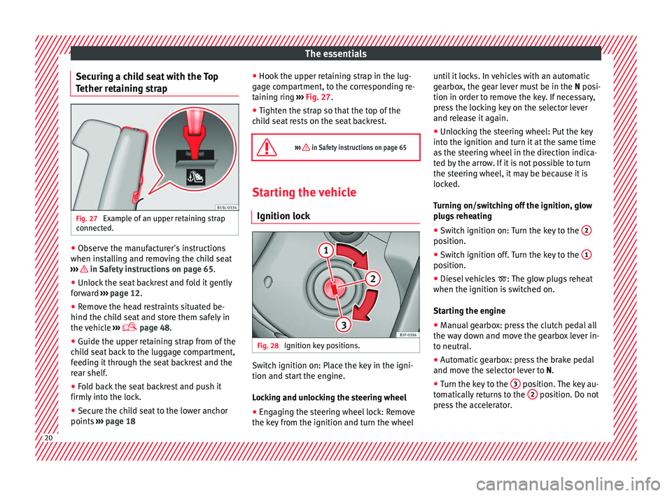
aining strapFig. 27
Example of an upper retaining strap
c onnect
ed. â
Observe the manufacturer's instructions
when in s
t
alling and removing the child seat
âºâºâº in Safety instructions on page 65.
â Unlock the seat backrest and fold it gently
f or
w
ard âºâºâº page 12.
â Remove the head restraints situated be-
hind the chil
d seat and store them safely in
the vehicle âºâºâº
ï© page 48.
â Guide the upper retaining strap from of the
chil
d seat back to the luggage compartment,
feeding it through the seat backrest and the
rear shelf.
â Fold back the seat backrest and push it
firmly int
o the lock.
â Secure the child seat to the lower anchor
points âºâº
⺠page 18 â
Hook the upper r
etaining strap in the lug-
gage compartment, to the corresponding re-
taining ring âºâºâº Fig. 27.
â Tighten the strap so that the top of the
chil
d seat rests on the seat backrest.
ïª
âºâºâº in Safety instructions on page 65 Starting the vehicle
Ignition lock Fig. 28
Ignition key positions. Switch ignition on: Place the key in the igni-
tion and s
t
ar
t the engine.
Locking and unlocking the steering wheel
â Engaging the steering wheel lock: Remove
the key fr
om the ignition and turn the wheel until it locks. In vehicles with an automatic
gearbo
x, the gear lever must be in the N posi-
tion in order to remove the key. If necessary,
press the locking key on the selector lever
and release it again.
â Unlocking the steering wheel: Put the key
into the ignition and turn it
at the same time
as the steering wheel in the direction indica-
ted by the arrow. If it is not possible to turn
the steering wheel, it may be because it is
locked.
Turning on/switching off the ignition, glow
plugs reheating
â Switch ignition on: Turn the key to the 2 position.
â
Switch ignition off. Turn the key to the 1 position.
â
Diesel vehicles ï¤: The glo
w p
lugs reheat
when the ignition is switched on.
Starting the engine
â Manual gearbox: press the clutch pedal all
the way
down and move the gearbox lever in-
to neutral.
â Automatic gearbox: press the brake pedal
and move the sel
ector lever to N.
â Turn the key to the 3 position. The key au-
t om
atic
ally returns to the 2 position. Do not
pr e
s
s the accelerator. 20
Page 24 of 232
The essentials
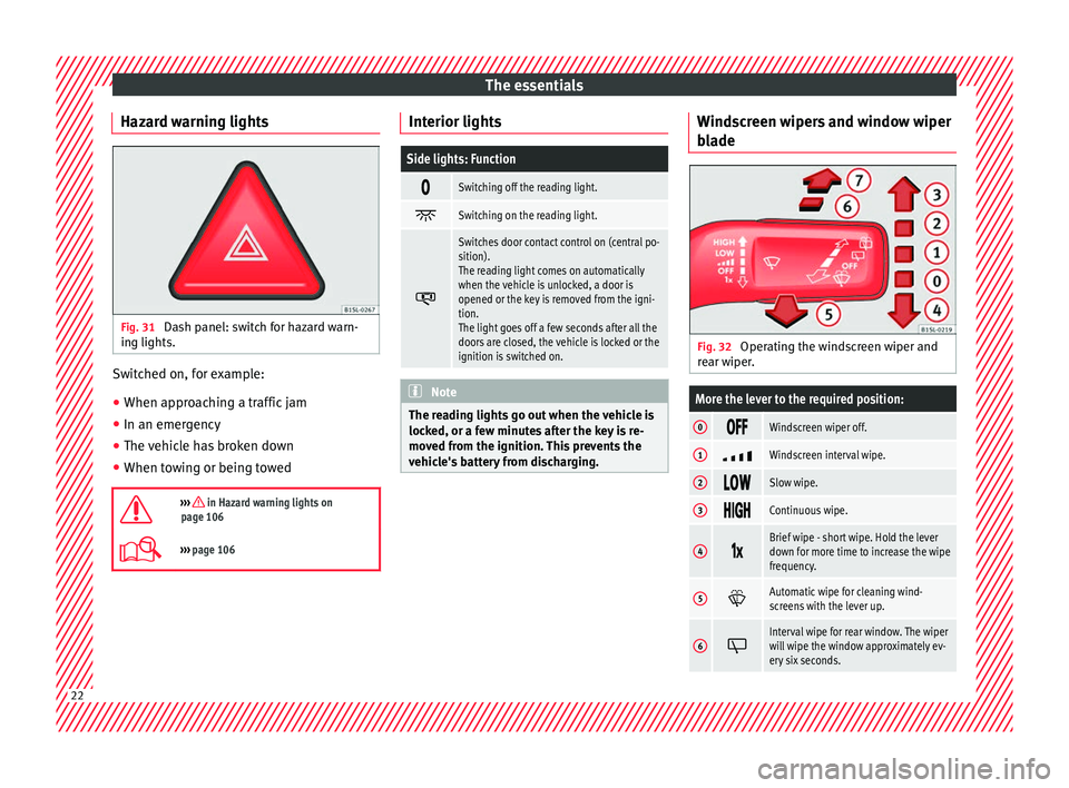
Hazard warning lights Fig. 31
Dash panel: switch for hazard warn-
in g lights. Switched on, for example:
â
When approaching a traffic jam
â In an emergency
â The vehicle has broken down
â When towing or being towed
ïªâºâºâº in Hazard warning lights on
page 106
ï©âºâºâº page 106 Interior lights
Side lights: Function
ï
Switching off the reading light.
ïº
Switching on the reading light.
ï´
Switches door contact control on (central po-
sition).
The reading light comes on automatically
when the vehicle is unlocked, a door is
opened or the key is removed from the igni-
tion.
The light goes off a few seconds after all the
doors are closed, the vehicle is locked or the
ignition is switched on.
Note
The reading lights go out when the vehicle is
lock ed, or a f
ew minutes after the key is re-
moved from the ignition. This prevents the
vehicle's battery from discharging. Windscreen wipers and window wiper
b
l
a
de Fig. 32
Operating the windscreen wiper and
r e
ar w
iper.
More the lever to the required position:
0 ïïïWindscreen wiper off.
1
ïºWindscreen interval wipe.
2
ïïïSlow wipe.
3
ïïïïContinuous wipe.
4
ï±ï³Brief wipe - short wipe. Hold the lever
down for more time to increase the wipe
frequency.
5
ï·Automatic wipe for cleaning wind-
screens with the lever up.
6
ïºInterval wipe for rear window. The wiper
will wipe the window approximately ev-
ery six seconds.
22
Page 33 of 232
The essentials
Fluid Level control Fi l
lin
g the fuel tank
Fuel tank capacity
Petrol enginesAround 35.0 l,
of which approximately 4.0 are the reserve.
Natural gas en-
gineNatural gas: approx. 11 kg; of whichmax. 1.5 kg reserve
Petrol: approx. 10 l; of which approx. 5 l reserve
Windscreen washer tank capacity
The washer bottle capacity is approximately 3 litres.Fuel
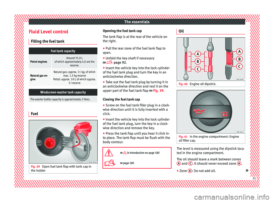
Fig. 39
Open fuel tank flap with tank cap in
the ho l
der Opening the fuel tank cap
The t
ank fl
ap is at the rear of the vehicle on
the right.
â Pull the rear zone of the fuel tank flap to
open.
â Unfold the key shaft if necessary
âºâºâº
ï© page 92.
â Insert the vehicle key into the lock cylinder
of the fuel
tank plug and turn the key in an
anticlockwise direction.
â Take out the fuel tank plug by turning it in
an anticlock
wise direction and rest it on the
upper part of the fuel tank flap âºâºâº Fig. 39.
Closing the fuel tank cap
â Screw on the fuel tank filler plug in a clock-
wise dir
ection until it is fully inserted with a
click.
â Insert the vehicle key into the lock cylinder
of the fuel
tank plug, turn the key in a clock-
wise direction and remove the key.
â Press the tank flap until you hear it click in-
to pl
ace. The tank flap must be flush with the
body contour.
ïª
âºâºâº in Introduction on page 183
ï©âºâºâº page 185 Oil
Fig. 40
Engine oil dipstick. Fig. 41
In the engine compartment: Engine
oi l
fi
ller cap. The level is measured using the dipstick loca-
t
ed in the en
gine c
ompartment.
The oil should leave a mark between zones A and
C . It should never exceed zone
A .
â Zone A : Do not add oil.
» 31
Page 59 of 232
Seat belts
â The l ap p
ar
t of the seat belt must lie across
the pelvis, never across the stomach.
â The seat belt must lie flat and fit comforta-
bly. P
ull the belt tight if necessary to take up
any slack.
In the case of pregnant women , the seat belt
must lie evenly across the chest and as low
as possible over the pelvis, never across the
stomach and must be worn properly at all
times during the pregnancy âºâºâº Fig. 73.
Adapting the position of the belt webbing to
your size
The seat belt can be adapted using the fol-
lowing equipment:
â Front seat height adjustment. WARNING
An incorrectly worn seat belt web can cause
sever e or f
atal injuries in the event of an acci-
dent.
â The seat belt cannot offer its full protection
unl
ess the seat backrest is in an upright posi-
tion and the seat belt is worn correctly, ac-
cording to your size.
â Unbuckling your seat belt while the vehicle
is in motion c
an cause severe or fatal injuries
in the event of an accident or sudden braking.
â The seat belt itself or a loose seat belt can
cause sev
ere injuries if the belt moves from hard areas of the body to soft areas (e.g. the
st
om
ach).
â The shoulder part of the seat belt must lie
on the centre of
the shoulder, never across
the neck or the arm.
â The seat belt must lie flat and fit comforta-
bly on the t
orso
â The lap part of the seat belt must lie across
the pelvis, nev
er across the stomach. The
seat belt must lie flat and fit comfortably on
the pelvis Pull the belt tight if necessary to
take up any slack.
â For pregnant women, the lap part of the
seat belt
must lie as low as possible over the
pelvis and always lie flat, âsurroundingâ the
stomach.
â Do not twist the seat belt while it is fas-
tened.
â Never p
ull the seat belt away from your
body us
ing your hand.
â Do not lie the seat belt across rigid or frag-
ile o
bjects, e.g. glasses, pens or keys.
â Never use seat belt clips, retaining rings or
simil
ar instruments to alter the position of
the belt webbing. Note
If your physical constitution prevents you
from m aint
aining the correct position of the
belt webbing, contact a specialised workshop
for help with any special devices to ensure
the optimum protection of the seat belt and airbag. SEAT recommends taking your car in
for t
ec
hnical service. Seat belt tensioners
Autom atic
belt retractor, belt tension-
er, belt tension limiter Seat belts are part of the vehicle safety con-
cept
âº
âºâº page 58 and consist of the follow-
ing important functions:
Automatic belt retainer
Every seat belt is equipped with an automatic
belt retainer on the shoulder belt. If the belt
is pulled slowly or during normal driving, the
system allows for total freedom of movement
on the shoulder belt. However, during sud-
den braking, during travel in mountains or
bends and during acceleration, the automat-
ic belt retainer on the seat belt is locked is
pulled quickly.
Belt tensioners
The seat belts for the occupants in the front
seats are equipped with belt tensioners.
Sensors trigger the belt tensioners during se-
vere head-on, lateral and rear collisions and
retract and tighten the seat belts. If the seat
belt is loose, it is retracted to reduce the for-
wards movement of occupants or movement »
57
Technical data
Advice
Operation
Emergencies
Safety