instrument panel Seat Toledo 2013 Owner's manual
[x] Cancel search | Manufacturer: SEAT, Model Year: 2013, Model line: Toledo, Model: Seat Toledo 2013Pages: 258, PDF Size: 3.94 MB
Page 35 of 258
33
Airbag system
Control lamp for airbag and seat belt tensioner
This control lamp monitors the airbag and seat belt tension-
er system.
The control lamp monitors all airbags and seat belt tensioners in the vehi-
cle, including control units and wiring connections.
Monitoring of airbag and belt tensioner system
Both the airbag and belt tensioner systems operation is constantly moni-
tored electronically. Each time the ignition is switched on, the control lamp
lights for several seconds and the instrument panel display* shows AIR-
BAG/TENSIONER.
The system must be checked when the control lamp :
● does not light up when the ignition is switched on
● turns off after 4 seconds after the ignition is switched on
● turns off and then lights up again after the ignition is switched on
● lights up or flashes while the vehicle is moving
In the event of a malfunction, the warning lamp remains on continuously. In
addition, depending on the malfunction, a fault message appears in the in-
strument panel display for approx. 10 seconds and a short audible warning
is given. In this event, you should have a specialised workshop check the
system immediately.
If any of the airbags are disabled by a Technical Service, the warning lamp
lights for several seconds more after the verification and will turn off if there
is no fault.WARNING
● If there is a malfunction, the airbag and belt tensioner system cannot
properly perform its protective function.
● If a malfunction occurred, have the system checked immediately by a
specialised workshop. Otherwise, in the event of an accident, the airbag
system and belt tensioners may not be triggered, or may not be triggered
correctly.
Repairs, maintenance and disposal of airbags
The parts of the airbag system are installed in various places in your vehi-
cle. If work is carried out on the airbag system or parts have to be removed
and fitted on the system when performing other repair work, parts of the air-
bag system may be damaged. In the event of an accident this could cause
the airbag to inflate incorrectly or not inflate at all.
The relevant safety requirements must be observed when the vehicle or
components of the airbag are scrapped. Specialised workshops and vehicle
disposal centres are familiar with these requirements.
WARNING
● If repairs are not carried out by a professional, or if the airbags are
used incorrectly, the risk of severe or fatal injuries is increased. The air-
bags may fail to inflate, or could inflate in the wrong circumstances.
● Do not cover or stick anything on the steering wheel hub or the sur-
face of the airbag unit on the passenger side of the dash panel, and do
not obstruct or modify them in any way.
● It is important not to attach any objects such as cup holders or tele-
phone mountings to the surfaces covering the airbag units.
Safety FirstOperating instructionsPractical TipsTechnical specifications
Page 57 of 258
55
Controls and displays
Operating instructions Controls and displays
Overview
Electric window controls . . . . . . . . . . . . . . . . . . . . . . . . . . . . . . . . . . . 95
Control for adjusting electric exterior mirrors . . . . . . . . . . . . . . . .109
Air outlets . . . . . . . . . . . . . . . . . . . . . . . . . . . . . . . . . . . . . . . . . . . . . . . . 129
Multifunction switch lever:
– turn signals, main beams, parking lights, headlight flash-
er . . . . . . . . . . . . . . . . . . . . . . . . . . . . . . . . . . . . . . . . . . . . . . . . . . . . . . 100
– cruise control . . . . . . . . . . . . . . . . . . . . . . . . . . . . . . . . . . . . . . . . . . 152
Steering wheel:
– with horn
– with the driver front airbag . . . . . . . . . . . . . . . . . . . . . . . . . . . . . . 35
– with controls for audio, navigation system and telephone .78
General instrument panel: instruments and warning lamps . .55
Multifunction switch lever:
– multifunction display . . . . . . . . . . . . . . . . . . . . . . . . . . . . . . . . . . . 61
– Windscreen wiper and washer . . . . . . . . . . . . . . . . . . . . . . . . . . . 106
Air outlets . . . . . . . . . . . . . . . . . . . . . . . . . . . . . . . . . . . . . . . . . . . . . . . . 129
Depending on the equipment:
– audio system
– navigation system
Hazard warning lights switch . . . . . . . . . . . . . . . . . . . . . . . . . . . . . . 101
Control lamp for front passenger airbag deactivated warning
lamp . . . . . . . . . . . . . . . . . . . . . . . . . . . . . . . . . . . . . . . . . . . . . . . . . . . . . 44
1234
5
67
89
1011
Front passenger airbag switch
. . . . . . . . . . . . . . . . . . . . . . . . . . . . . 44
Passenger side storage compartment . . . . . . . . . . . . . . . . . . . . . .123
Front passenger airbag . . . . . . . . . . . . . . . . . . . . . . . . . . . . . . . . . . . . 35
Switch for the lights and the main lights range control . . . . . .97, 99
Bonnet release lever . . . . . . . . . . . . . . . . . . . . . . . . . . . . . . . . . . . . . . 183
Fuse housing . . . . . . . . . . . . . . . . . . . . . . . . . . . . . . . . . . . . . . . . . . . . . 220
Steering column adjustment lever . . . . . . . . . . . . . . . . . . . . . . . . . . 140
Ignition lock . . . . . . . . . . . . . . . . . . . . . . . . . . . . . . . . . . . . . . . . . . . . . . 141
Driver seat heating control . . . . . . . . . . . . . . . . . . . . . . . . . . . . . . . . . 112
ASR switch . . . . . . . . . . . . . . . . . . . . . . . . . . . . . . . . . . . . . . . . . . . . . . . . 144
Central lock button . . . . . . . . . . . . . . . . . . . . . . . . . . . . . . . . . . . . . . . . 88
Depending on the equipment:
– gear lever (manual gearbox) . . . . . . . . . . . . . . . . . . . . . . . . . . . . 145
– selector lever (automatic gearbox) . . . . . . . . . . . . . . . . . . . . . . .147
Depending on the equipment:
– drink holder . . . . . . . . . . . . . . . . . . . . . . . . . . . . . . . . . . . . . . . . . . . . 120
– ashtray holder . . . . . . . . . . . . . . . . . . . . . . . . . . . . . . . . . . . . . . . . . . 121
glove compartment/storage compartment . . . . . . . . . . . . . . . . . .123
Heated rear window control . . . . . . . . . . . . . . . . . . . . . . . . . . . . . . . . 104
Passenger seat heating control . . . . . . . . . . . . . . . . . . . . . . . . . . . . 112
Depending on the equipment:
– heating controls . . . . . . . . . . . . . . . . . . . . . . . . . . . . . . . . . . . . . . . . 130
– air conditioning controls . . . . . . . . . . . . . . . . . . . . . . . . . . . . . . . . 132
– Climatronic controls . . . . . . . . . . . . . . . . . . . . . . . . . . . . . . . . . . . . 135
121314151617181920212223
24
25262728
Safety FirstOperating instructionsPractical TipsTechnical specifications
Page 59 of 258
57
Controls and displays
Instruments and warning lamps
General instrument panel – summary
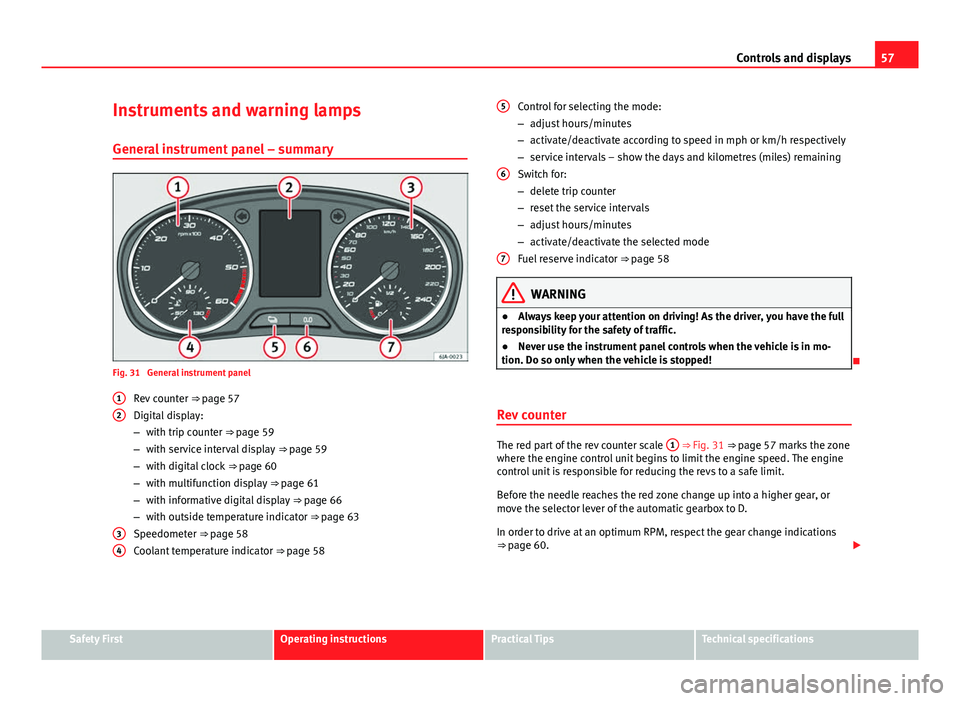
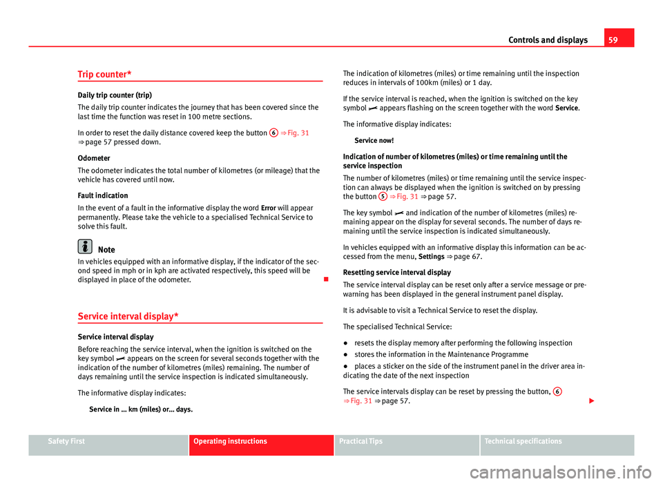
Fig. 31 General instrument panel Rev counter ⇒ page 57
Digital display:
– with trip counter
⇒ page 59
– with service interval display
⇒ page 59
– with digital clock
⇒ page 60
– with multifunction display
⇒ page 61
– with informative digital display
⇒ page 66
– with outside temperature indicator
⇒ page 63
Speedometer ⇒ page 58
Coolant temperature indicator ⇒ page 58
1
2
34
Control for selecting the mode:
–
adjust hours/minutes
– activate/deactivate according to speed in mph or km/h respectively
– service intervals – show the days and kilometres (miles) remaining
Switch for:
– delete trip counter
– reset the service intervals
– adjust hours/minutes
– activate/deactivate the selected mode
Fuel reserve indicator ⇒ page 58
WARNING
● Always keep your attention on driving! As the driver, you have the full
responsibility for the safety of traffic.
● Never use the instrument panel controls when the vehicle is in mo-
tion. Do so only when the vehicle is stopped!
Rev counter
The red part of the rev counter scale 1 ⇒ Fig. 31 ⇒
page 57 marks the zone
where the engine control unit begins to limit the engine speed. The engine
control unit is responsible for reducing the revs to a safe limit.
Before the needle reaches the red zone change up into a higher gear, or
move the selector lever of the automatic gearbox to D.
In order to drive at an optimum RPM, respect the gear change indications
⇒ page 60.
5
6
7
Safety FirstOperating instructionsPractical TipsTechnical specifications
Page 60 of 258
58Controls and displays
For the sake of the environment
Changing to higher gears in advance helps to reduce fuel consumption and
noise levels, helps to protect the environment and benefits both the useful
life and the reliability of the engine.
Speedometer
Speed warning
An audible warning will be heard on exceeding 120 km/h (75 mph). If the
speed falls below this limit, the audible warning switches off.
Note
This function is only valid for certain countries.
Coolant temperature gauge
The coolant temperature gauge 4
⇒ Fig. 31
⇒ page 57 only works when
the ignition is switched on.
Damage to the engine can be avoided by observing the indications regard-
ing the temperature zones.
Engine cold
If the needle is still on the left of the scale, the engine has not yet reached
operating temperature. Avoid high engine speeds, hard acceleration and
submitting the engine to high loads.
Operating temperature zone
When the needle has reached the central part of the scale, this means the
engine has reached operating temperature. Running the engine at full throt- tle and the high temperatures involved can cause the needle to be posi-
tioned in the zone on the right.
CAUTION
The additional headlights and other parts placed in front of the fresh air in-
lets reduce the effect of engine cooling. With high outside temperatures
and engine speeds a risk becomes present of the engine overheating
⇒ page 72, Coolant level and temperature .
Fuel gauge
The fuel gauge 7 ⇒ Fig. 31 ⇒
page 57 operates only when the ignition is
switched on.
The fuel tank has a capacity of approx. 55 litres. When the needle reaches
the reserve area, the warning symbol ⇒ page 75 lights up on the gener-
al instrument panel and an audible warning can be heard.
CAUTION
Never completely empty the tank! An irregularity in the fuel supply system
can cause irregularities when the engine is running. Unburned fuel can
reach the exhaust gas system, which can cause deterioration of the catalytic
converter.
Note
Some vehicles come fitted with the fuel gauge on the general instrument
panel.
Page 61 of 258
59
Controls and displays
Trip counter*
Daily trip counter (trip)
The daily trip counter indicates the journey that has been covered since the
last time the function was reset in 100 metre sections.
In order to reset the daily distance covered keep the button 6
⇒ Fig. 31
⇒ page 57 pressed down.
Odometer
The odometer indicates the total number of kilometres (or mileage) that the
vehicle has covered until now.
Fault indication
In the event of a fault in the informative display the word Error will appear
permanently. Please take the vehicle to a specialised Technical Service to
solve this fault.
Note
In vehicles equipped with an informative display, if the indicator of the sec-
ond speed in mph or in kph are activated respectively, this speed will be
displayed in place of the odometer.
Service interval display*
Service interval display
Before reaching the service interval, when the ignition is switched on the
key symbol appears on the screen for several seconds together with the
indication of the number of kilometres (miles) remaining. The number of
days remaining until the service inspection is indicated simultaneously.
The informative display indicates:
Service in … km (miles) or… days. The indication of kilometres (miles) or time remaining until the inspection
reduces in intervals of 100km (miles) or 1 day.
If the service interval is reached, when the ignition is switched on the key
symbol
appears flashing on the screen together with the word Service.
The informative display indicates: Service now!
Indication of number of kilometres (miles) or time remaining until the
service inspection
The number of kilometres (miles) or time remaining until the service inspec-
tion can always be displayed when the ignition is switched on by pressing
the button 5
⇒ Fig. 31 ⇒
page 57.
The key symbol and indication of the number of kilometres (miles) re-
maining appear on the display for several seconds. The number of days re-
maining until the service inspection is indicated simultaneously.
In vehicles equipped with an informative display this information can be ac-
cessed from the menu, Settings ⇒ page 67.
Resetting service interval display
The service interval display can be reset only after a service message or pre-
warning has been displayed in the general instrument panel display.
It is advisable to visit a Technical Service to reset the display.
The specialised Technical Service:
● resets the display memory after performing the following inspection
● stores the information in the Maintenance Programme
● places a sticker on the side of the instrument panel in the driver area in-
dicating the date of the next inspection
The service intervals display can be reset by pressing the button, 6
⇒ Fig. 31 ⇒
page 57.
Safety FirstOperating instructionsPractical TipsTechnical specifications
Page 62 of 258
60Controls and displays
In vehicles equipped with an informative display the service interval display
can be reset from the menu, Settings ⇒ page 67.
CAUTION
We advise against resetting the service interval display yourself, given that
this action could cause an imbalance in the service intervals, and as a re-
sult, faults in the vehicle.
Note
● Never reset the display between service intervals as this could lead to
erroneous indications.
● After disconnecting the battery of the vehicle, the service interval dis-
play values remain stored.
● If the general instrument panel is changed after a repair, the correct val-
ues must be input in the service interval display. This operation is carried
out by a specialised service.
● After resetting the display with flexible service intervals, the information
will be indicated in the same way as vehicles with fixed service intervals.
Therefore, we recommend that a SEAT Authorised Service resets the service
interval display, who will do so correctly using diagnostics equipment.
● For more detailed information please consult the Maintenance Pro-
gramme.
Digital clock
The clock is set using the buttons 5 to 6
⇒ Fig. 31
⇒ page 57.
Select the indication you want to change with button 5
and make the ad-
justment with button 6.
In vehicles equipped with an informative display this can be reset from the
menu, Time ⇒ page 67. Recommended gear display
Fig. 32 Recommended
gear display
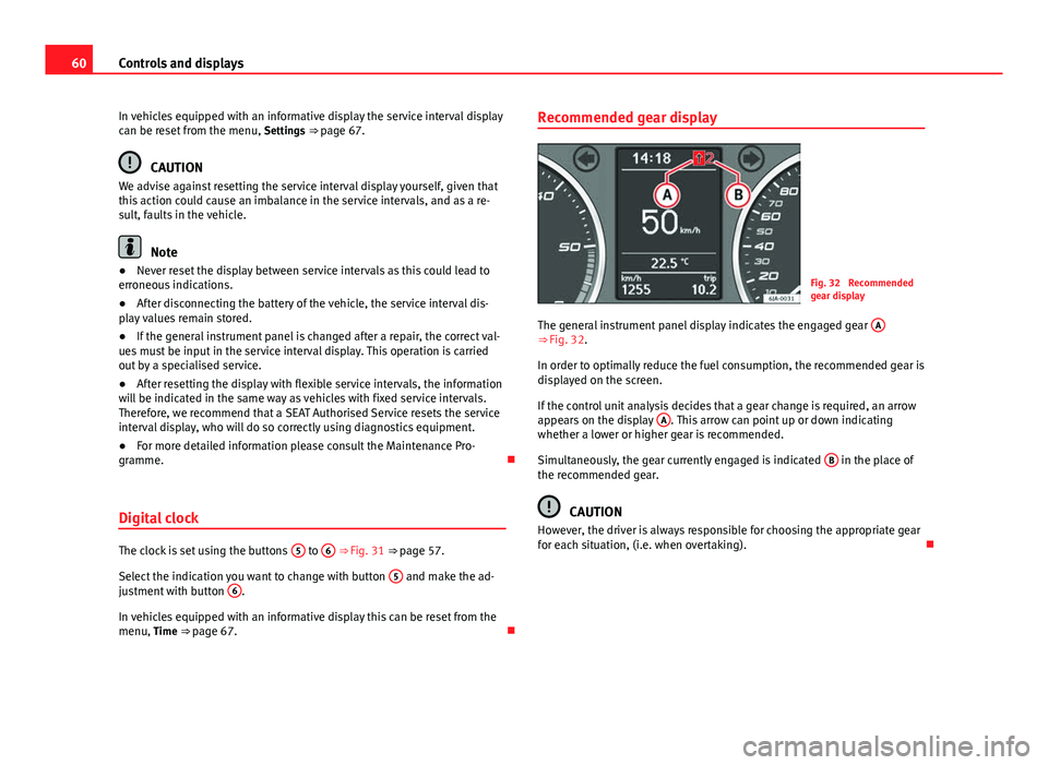
The general instrument panel display indicates the engaged gear A
⇒ Fig. 32.
In order to optimally reduce the fuel consumption, the recommended gear is
displayed on the screen.
If the control unit analysis decides that a gear change is required, an arrow
appears on the display A
. This arrow can point up or down indicating
whether a lower or higher gear is recommended.
Simultaneously, the gear currently engaged is indicated B
in the place of
the recommended gear.
CAUTION
However, the driver is always responsible for choosing the appropriate gear
for each situation, (i.e. when overtaking).
Page 70 of 258
68Controls and displays
Door, rear lid or bonnet open indicator
If at least one of the doors, rear lid or bonnet is open, a symbol is shown on
the informative display indicating that the door, rear lid or bonnet con-
cerned is open.
An audible warning is also given simultaneously if the vehicle is being driv-
en at a speed of above 6 km/h (4 mph).
Auto-check system
Vehicle status
When the ignition is switched on, some vehicle functions such as the condi-
tion of its systems are automatically checked.
The warning messages about eventual faults in addition to other informa-
tion is displayed on the informative display. This information is displayed
together with their respective symbols on the informative display or by
warning lamps that light up on the general instrument panel ⇒ page 69.
The option, Vehicle status, appears in the menu when at least one warning
message is present. The first of the warnings given is displayed upon se-
lecting this option. If there is more than one message present, this is dis-
played on the screen, i.e. 1/3. This means that the warning currently dis- played is the first of a total of three.
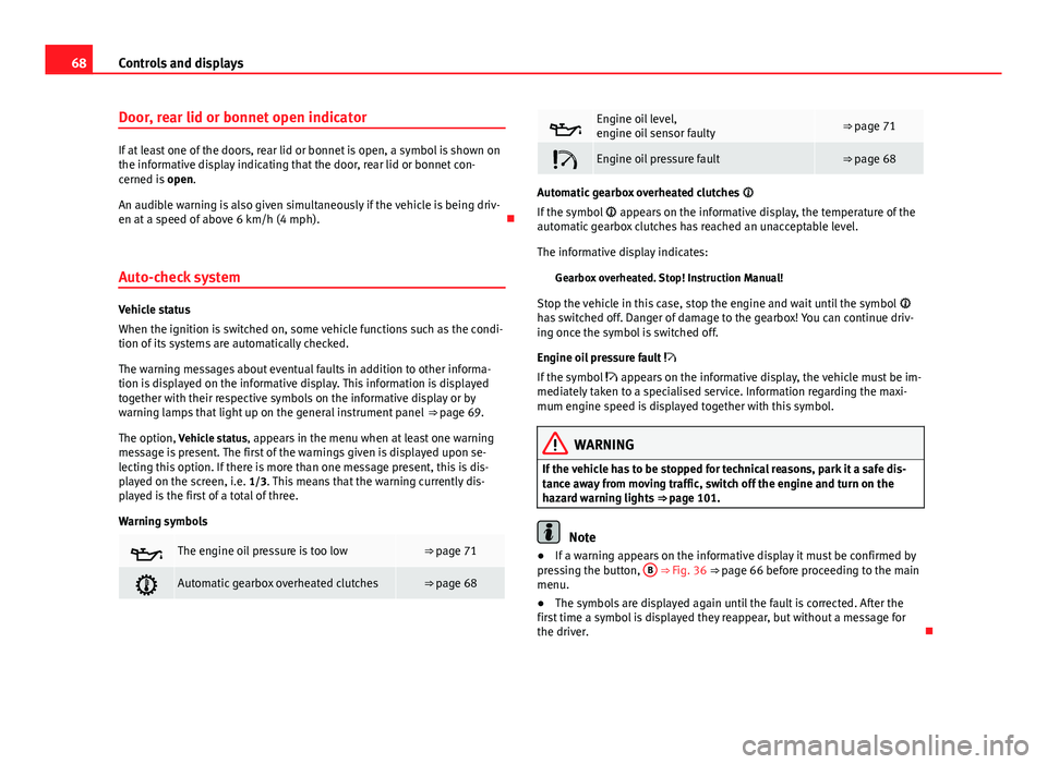
Warning symbols
The engine oil pressure is too low⇒ page 71
Automatic gearbox overheated clutches⇒ page 68
Engine oil level,
engine oil sensor faulty⇒ page 71
Engine oil pressure fault⇒ page 68
Automatic gearbox overheated clutches
If the symbol appears on the informative display, the temperature of the
automatic gearbox clutches has reached an unacceptable level.
The informative display indicates:
Gearbox overheated. Stop! Instruction Manual!
Stop the vehicle in this case, stop the engine and wait until the symbol
has switched off. Danger of damage to the gearbox! You can continue driv-
ing once the symbol is switched off.
Engine oil pressure fault
If the symbol appears on the informative display, the vehicle must be im-
mediately taken to a specialised service. Information regarding the maxi-
mum engine speed is displayed together with this symbol.
WARNING
If the vehicle has to be stopped for technical reasons, park it a safe dis-
tance away from moving traffic, switch off the engine and turn on the
hazard warning lights ⇒ page 101.
Note
● If a warning appears on the informative display it must be confirmed by
pressing the button, B
⇒ Fig. 36 ⇒
page 66 before proceeding to the main
menu.
● The symbols are displayed again until the fault is corrected. After the
first time a symbol is displayed they reappear, but without a message for
the driver.
Page 82 of 258
80Communication
Audio + Telephone system operation
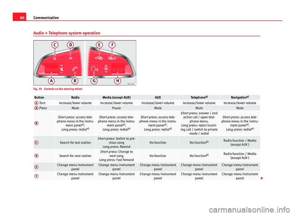
Fig. 39 Controls on the steering wheel
ButtonRadioMedia (except AUX)AUXTelephone a)Navigation a)A TurnIncrease/lower volumeIncrease/lower volumeIncrease/lower volumeIncrease/lower volumeIncrease/lower volumeA PressMutePauseMuteMuteMute
B
Short press:
access tele-
phone menu in the instru- ment panel a)
.
Long press: redial a)Short press:
access tele-
phone menu in the instru- ment panel a)
.
Long press: redial a)Short press:
access tele-
phone menu in the instru- ment panel a)
.
Long press: redial a)Short press:
answer / end
active call / open tele- phone menu.
Long press: reject incom-
ing call / switch to private mode / redialShort press: access tele-
phone menu in the instru- ment panel a)
.
Long press: redial a)
CSearch for last stationShort press:
Switch to pre-
vious song
Long press: RewindNo functionNo function b)Radio function / Media
(except AUX )
DSearch for next stationShort press: Change to
next song
Long press: Fast forwardNo functionNo function b)Radio function / Media
(except AUX )
EChange menu instrument panelChange menu instrumentpanelChange menu instrumentpanelChange menu instrumentpanelChange menu instrumentpanel
FChange menu instrument panelChange menu instrumentpanelChange menu instrumentpanelChange menu instrumentpanelChange menu instrumentpanel
Page 83 of 258

81
Communication
ButtonRadioMedia (except AUX)AUXTelephone a)Navigation a)
GActivating/deactivating
voice control a)Activating/deactivating
voice control a)Activating/deactivating
voice control a)No functionb)Activating/deactivating
voice control
H TurnNext / previous preset c)Next / previous presetc)Operates on the instrument
panel menu you are inOperates on the instru-
ment panel menu you are inOperates on the instru-
ment panel menu you are in
H Press
Operates on the MFA or
confirms instrument panel
menu option depending on the menu optionOperates on the MFA or
confirms instrument panel
menu option depending on the menu optionOperates on the MFA or
confirms instrument panel
menu option depending on the menu optionOperates on the MFA or
confirms instrument panel menu option depending on the menu optionOperates on the MFA or
confirms instrument panel menu option depending on the menu option
a) Depending on the vehicle equipment.
b) In call-in-progress situation, if not Radio/Media function (except AUX).
c) Only if the instrument panel is in the Audio menu.
Multimedia AUX-IN and MDI Inputs
Fig. 40 AUX-IN input/MDI input The operating description is located in the respective Instruction Manuals of
the audio system or the navigation system.
AUX-IN Input
The AUX-IN input is located in one of the following places:
●
in the centre console between the front seats ⇒ Fig. 40 - ;
● above the storage compartment in the front centre console ⇒ Fig. 40 -
;
● in the front panel of the SEAT Media System 2.2 navigation system.
The purpose of the AUX-IN input is to connect external devices in order to
play music (i.e. iPod ®
or an mp3 player) using the factory-fitted audio sys-
tem or the navigation system.
MDI Input
The MDI input is located above the storage compartment in the front centre
console ⇒ Fig. 40 - ;
Safety FirstOperating instructionsPractical TipsTechnical specifications
Page 89 of 258
87
Opening and closing
If the Safe lock is out of service, the control lamp on the driver door will
flash quickly for 2 seconds before switching off for 30 seconds and then
flashing at a slower rate.
The Safe lock is re-activated on unlocking and locking the vehicle again.
If the vehicle is locked and the Safe lock is deactivated, the vehicle can be
opened from inside by pulling on the door handle.
WARNING
Do not leave people or animals in locked vehicles with the Safe lock acti-
vated: the doors and windows cannot then be opened from the inside.
Doors locked in this manner could delay assistance in an emergency.
Risk of death!
Note
● The anti-theft alarm switches on automatically when the vehicle is
locked, even if the Safe lock is deactivated. The Vehicle interior monitoring,
however, is not activated.
● Given that the Safe function will be activated on locking the vehicle,
CHECK DEADLOCK will be shown on the general instrument panel display. On
vehicles equipped with an informative display, Caution SAFE! On-board docu-
mentation! will be indicated. Unlocking the vehicle with the key
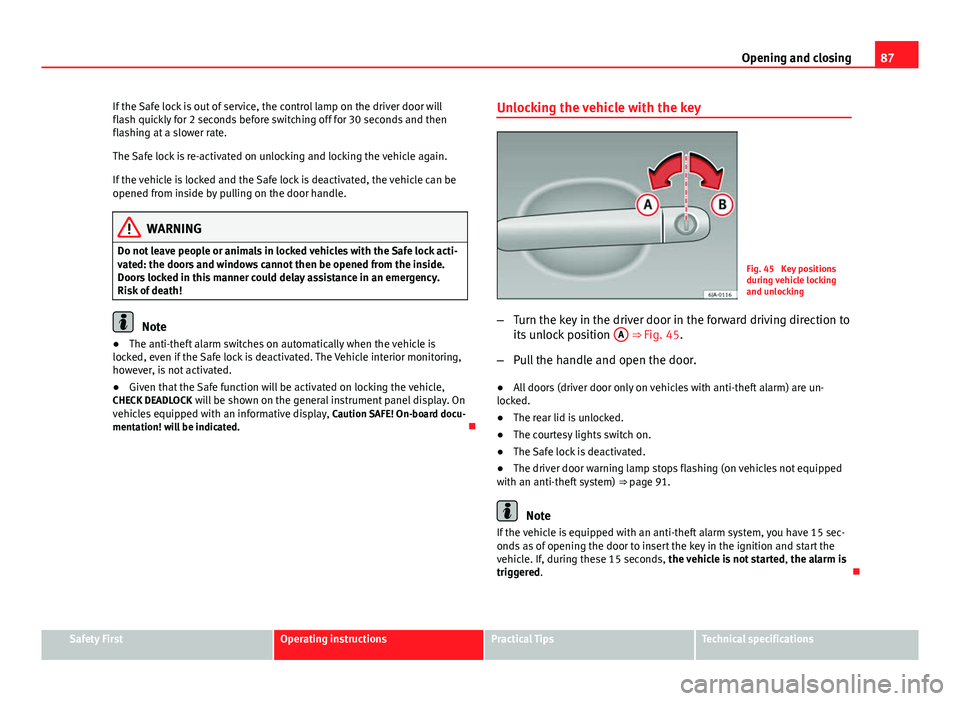
Fig. 45 Key positions
during vehicle locking
and unlocking
– Turn the key in the driver door in the forward driving direction to
its unlock position A
⇒ Fig. 45.
– Pull the handle and open the door.
● All doors (driver door only on vehicles with anti-theft alarm) are un-
locked.
● The rear lid is unlocked.
● The courtesy lights switch on.
● The Safe lock is deactivated.
● The driver door warning lamp stops flashing (on vehicles not equipped
with an anti-theft system) ⇒ page 91.
Note
If the vehicle is equipped with an anti-theft alarm system, you have 15 sec-
onds as of opening the door to insert the key in the ignition and start the
vehicle. If, during these 15 seconds, the vehicle is not started , the alarm is
triggered.
Safety FirstOperating instructionsPractical TipsTechnical specifications