PAGE Seat Toledo 2014 Owner's manual
[x] Cancel search | Manufacturer: SEAT, Model Year: 2014, Model line: Toledo, Model: Seat Toledo 2014Pages: 200, PDF Size: 4.37 MB
Page 167 of 200

Fuses and bulbs
Changing fuses in the engine
compartment Fig. 140
Battery: fuse cover (version 1). Fig. 141
Battery: fuse cover (version 2). ●
Press the flexible tabs on the fuse box cov-
er in the direction indicated by the arrows 1 ›››
Fig. 140 .
● Remo
ve the cover by sliding it in the direc-
tion indicated by arrow 2 .
● Use a flat-headed screwdriver to unlock the
holes 3 .
● Open the cover in the direction indicated
by the arrow 4 .Replacing a blown fuse
Fig. 142
Image of a blown fuse Preparation
● Switch off the ignition, lights and all elec-
trical equipment.
● Open the corresponding fuse box
››› page 164 .
Identif y
ing a blown fuse
A fuse is blown if its metal strip is ruptured
››› Fig. 142.
Point a lamp at the fuse. This will make it
easier to see if the fuse is blown.
To replace a fuse ● Remove the fuse.
● Replace the blown fuse by one with an
identical amperage rating (same colour and
mark
ings) and identical size ››› .
»
165
Technical specifications
Advice
Operation
Safety
Page 174 of 200
Advice
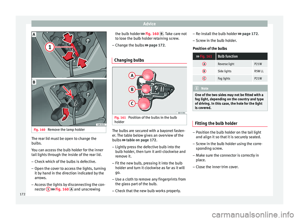
Fig. 160
Remove the lamp holder The rear lid must be open to change the
bulbs.
You can access the bulb holder for the inner
tail lights through the inside of the rear lid.
–
Check which of the bulbs is defective.
– Open the cover to access the lights, turning
it by hand in the direction indicated by the
arrows.
– Access the lights by disconnecting the con-
nector 1
››› Fig. 160 and u
nscrewing the b ulb holder
››› Fig. 160
. Take care not
to lose the bulb holder retaining screw.
– Change the bulbs ››› page 172.
Changing bulbs Fig. 161
Position of the bulbs in the bulb
holder The bulbs are secured with a bayonet fasten-
er. The table below gives an overview of the
bulbs
››› table on page 172 .
– Lightly pr
ess the defective bulb into the
bulb holder, then turn it anti-clockwise and
remove it.
– Fit the new bulb, pressing it into the bulb
holder and turn it clockwise as far as it will
go.
– Use a cloth to remove any fingerprints from
the glass part of the bulb.
– Check that the new bulb works properly. –
Re-install the bulb holder ››› page 172.
– Screw in the bulb holder.
Position of the bulbs
››› Fig. 161Bulb function
AReverse lightP21W
BSide lightsR5W LL
CFog lightsP21W Note
One of the two sides may not be fitted with a
fog light, depending on the country and type
of driving. In this case, the hole for the light
is covered. Fitting the bulb holder
–
Position the bulb holder on the tail light
and align it so that it is securely seated.
– Screw in the bulb holder using the corre-
sponding screw.
– Make sure the connector is correctly in
place.
– Close the inner trim cover.
172
Page 199 of 200

SEAT S.A. is permanently concerned about continuous development of its t\
ypes and models. For this reason we ask you to under-
stand, that at any given time, changes regarding shape, equipment and te\
chnique may take place on the car delivered. For this reason
no right at all may derive based on the data, drawings and descriptions \
in this current handbook.
All texts, illustrations and standards in this handbook are based on the\
status of information at the time of printing. Except for error
or omission, the information included in the current handbook is valid a\
s of the date of closing print.
Re-printing, copying or translating, whether total or partial is not all\
owed unless SEAT allows it in written form.
SEAT reserves all rights in accordance with the “Copyright” Act.
All rights on changes are reserved.
❀This paper has been manufactured using bleached non-chlorine cellulose.
© SEAT S.A. - Reprint: 15.11.14
About this manual
This manual contains a description of the
equipment supplied with the vehicle at the
time this manual was published. Some of the
units described herein will not be available
until a later date or are only available in cer -
tain markets.
Because this is a general manual for the
ALTEA range, some of the equipment and
functions that are described in this manual
are not included in all types or variants of the
model; they may vary or be modied depend -
ing on the technical requirements and on the
market; this is in no way deceptive advertis-
ing.
The illustrations are intended as a general
guide and may vary from the equipment tted
in your vehicle in some details.
The steering indications (left, right, forward,
reverse) appearing in this manual refer to the
normal driving movements of the vehicle ex -
cept when otherwise indicated.
* The equipment marked with an aster -
isk* is tted as standard only in certain
versions, and is only supplied as op -
tional extras for some versions, or are
only offered in certain countries. ®
All registered marks are indicated with
®. Although the copyright symbol does
not appear, it is a copyrighted mark.
>> The section is continued on the follow -
ing page.
WARNING
Texts preceded by this symbol contain infor -
mation on safety. They warn you about possi -
ble dangers of accident or injury.
CAUTION
Texts with this symbol draw your attention to
potential sources of damage to your vehicle.
For the sake of the environment
Texts preceded by this symbol contain rele-
vant information concerning environmental
protection.
Note
Texts preceded by this symbol contain additio -
nal information.
This manual is divided into ve large parts,
which are:
1. Safety
2. Operation
3. Tips
4. Technical data
5. Alphabetical index
At the end of this manual, there is a detailed
alphabetical index that will help you quickly
nd the information you require.