tow bar Seat Toledo 2014 Owner's manual
[x] Cancel search | Manufacturer: SEAT, Model Year: 2014, Model line: Toledo, Model: Seat Toledo 2014Pages: 200, PDF Size: 4.37 MB
Page 116 of 200

Operation
CAUTION
Switch off the Start-Stop system ››› page 107
before driving through a pool of water on the
road. Note
● The battery temperature may reflect
changes in outside temperature after several
hours. If the vehicle has been stopped out-
side at temperatures below zero or in direct
sunlight, for example, the battery tempera-
ture may take several hours to reach the val-
ues required for the correct operating of the
Start-Stop system.
● If the Climatronic system is operating auto-
matically, this could impair automatic engine
shut down under certain conditions. Towing bracket device
Driving the vehicle with a
trailer Technical requirements If your vehicle has a factory-fitted towing
bracket or is equipped with a selection of
SEAT Original Accessories, it meets all the rel-
evant technical and legal requirements.
In vehicles with a towing bracket it is possi-
ble to remove the ball joint, situated (togeth-
er with the special assembly instructions) in
the housing for the spare wheel in the vehi-
cle luggage compartment
›››
page 150, Vehi-
cle tool kit* .
Y our
vehicle is fitted with a 13-pole power
socket for the electrical connection between
the trailer and the vehicle. If the trailer you
are going to use has a 7-pin connector, the
corresponding adaptor, acquired from the
SEAT Original Accessories Catalogue, can be
used.
If a towing bracket is to be retro-fitted to the
car, it must be done according to the instruc-
tions of the towing bracket manufacturer. Note
Any queries that may arise can be directed to
an authorised SEAT dealer. Trailer weight
Trailer weight
The combined vehicle and trailer must be
balanced. To do so use the maximum permit-
ted towing bracket load. An insufficient
weight exerted by the trailer drawbar on the
ball joint of the towing bracket will have a
negative impact upon the response of the ve-
hicle-trailer assembly on the road.
Weight distribution
Distribute loads in the trailer so that heavy
objects are as near to the axle as possible.
Ensure that the objects do not move.
If the towing vehicle is empty and the trailer
loaded then the load distribution is incorrect.
However, if these conditions cannot be avoi-
ded, drive very slowly.
Tyre pressure values
Correct the tyre pressure in your vehicle to
“total load”
›››
page 144, Life cycle of tyres .
Trailer weight
Never exceed the authorised trailer weight
under any circumstances ›››
page 174, Tech-
nical specifications .
The trailer weights listed are only applicable
for altitudes up to 1000 m above sea level.
D
ue to lower air density, engine power de-
creases depending on the increase in
114
Page 118 of 200

Operation
Please observe the following indications
››› page 35, Coolant level and temperature
.
The coolant temperature can be reduced by
switching on the heating. WARNING
● Adjust your speed to suit the road and traf-
fic conditions.
● An electrical installation that is connected
incorrectly or by non-specialised personnel
can prevent the connection of the current to
the trailer and cause faults in the operation of
the electrical system throughout the entire
vehicle, leading to accidents and serious in-
jury.
● All electrical work must be carried out only
by specialised services.
● Never directly connect the trailer electrical
device to the electrical sockets of the reverse
driving lights or other sources of electrical
current. CAUTION
● Avoid corners, and sudden and sharp brak-
ing.
● Once the trailing arm has been removed,
place the corresponding cover on the hole of
the fastening point. This prevents dirt from
entering the hole – see the trailer system as-
sembly manual. Note
● In the event of frequent journeys with a
trailer, we recommend also having the vehi-
cle inspected in between the service inter-
vals.
● When connecting and disconnecting the
trailer, the handbrake must be applied.
● For technical reasons, trailers with LED re-
verse lights cannot be incorporated into the
vehicle anti-theft alarm system. Towing bracket device
Introduction If the vehicle is equipped with a towing
bracket device from the factory or is a genu-
ine SEAT accessory, it meets all national tech-
nical and legal requirements for towing.
Your vehicle is fitted with a 13-pin power
socket for the electrical connection between
the trailer and the vehicle. If the towing
bracket is equipped with a
7-pin connector,
y ou c
an use the corresponding available
adaptor that is a genuine SEAT accessory.
The towing device has a maximum vertical
load of 50 kg
. WARNING
● Before driving with the ball-headed bar fit-
ted, verify its correct assembly and place-
ment in the clamping bush.
● Do not use the ball-headed bar if it is not
correctly placed and fixed in the clamping
bush.
● Do not use the towing device for towing if it
is damaged or has missing parts.
● Do not modify or adapt the towing device
connection.
● Never disengage the ball-headed bar with
the trailer still hitched. CAUTION
Be careful not to damage the paint on the
bumper when handling the ball-headed bar. 116
Page 119 of 200

Towing bracket device
Description Fig. 99
Towing bracket device support for
hitching/ball-headed bar. The ball-headed bar is detachable. It is loca-
ted in the spare wheel compartment or in the
spare wheel compartment in the boot
››› page 150, Vehicle tool kit*.
Key to ››› Fig. 99
13-pin socket
Safety flange
1 2 Clamping bush
Clamping bush cap
Ball head cover
Ball-headed bar
Locking balls
Centred
Red marking on the manual regulator
Manual regulator
Key
Key slot cover
Red marking on the manual regulator
White marking on the ball-headed bar
Note
Contact an Authorised Service Partner if you
lose your key. 3
4
5
6
7
8
9
10
11
12
13
14 Placing in service position
Fig. 100
Placing in service position.
» 117Technical specifications
Advice
Operation
Safety
Page 120 of 200

Operation
Fig. 101
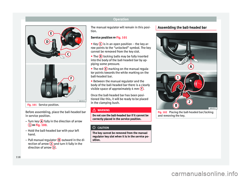
Service position. Before assembling, place the ball-headed bar
in service position.
–
Turn key A fully in the direction of arrow
1
››› Fig. 100 .
– Ho l
d the ball-headed bar with your left
hand.
– Pull manual regulator B outward in the di-
rection of arrow 2 and turn it fully in the
direction of arrow 3 .The manual regulator will remain in this posi-
tion.
Service position
› ››
Fig. 101
● K
ey C is in an open position – the key ar-
row points to the “unlocked” symbol. The key
cannot be removed from the key slot.
● The D locking balls may be fully inserted
into the body of the ball-headed bar by ap-
plying some pressure.
● The red E marking on the manual regula-
tor points towards the white marking on the
ball-headed bar.
● Between the manual regulator and the
body of the ball-headed bar there is a clearly
visible space of approximately 4 mm F .
Once the ball-headed bar has been posi-
tioned like this, it will be ready to be placed
in the clamping bush. WARNING
Do not use the ball-headed bar if it cannot be
correctly placed in the service position. CAUTION
The key cannot be removed from the manual
regulator key slot when it is in the service po-
sition. Assembling the ball-headed bar
Fig. 102
Placing the ball-headed bar/locking
and removing the key. 118
Page 121 of 200

Towing bracket device
Fig. 103
Placing the key slot cover. –
Remove the cap from the clamping bush 4›››
Fig. 99 by pulling downwards.
– Plac
e the ball-headed bar in the service po-
sition ››› page 117.
– Hol
d the ball-headed bar from underneath
››› Fig. 102
and push it into the clamping
bush as far as possible until you hear it
click into place ››› .
The manual regulator A
automatically turns
in the op po
site direction, adjusting to the
ball-headed bar ››› .
– Switch off the manual regulator lock with
key B by turning the key fully to the right
in the direction of arrow 1 – the arrow in
the key displays the “locked” symbol.
– Remove the key in the direction of arrow
2 .
– Place cover C over the manual regulator
lock in the direction of arrow 3
››› Fig. 103 .–
Verif
y the correct placement of the ball-
headed bar ››› page 119. WARNING
● Do not hold the manual regulator with your
hand when fitting the ball-headed bar since
you could sustain injuries to your fingers.
● When mounting the ball-headed bar, al-
ways lock it with a key and remove the key
from the slot.
● The ball-headed bar must not be in the
service position with the key in the key slot.
● If the ball-headed bar is not placed in the
service position you will not be able to place
it in the clamping bush. CAUTION
When removing the key, always place the
cover over the key slot of the manual regula-
tor to prevent dirt from entering. Note
Once removed, place the clamping bush cap
in an appropriate location in the boot. Verification of correct placement
Fig. 104
Correct placement of the ball-head-
ed bar. Before using the ball-headed bar, ensure it is
correctly fitted.
Ensure that:
● The ball-headed bar does not come out of
the clamping bush in a “jerky” manner.
● The red mark A
››› Fig. 104 on the manual
r e
gulator signals toward the white mark on
the ball-headed bar.
● The manual regulator is adjusted to the
ball-headed bar, leaving no space between
them.
● The regulator is locked and the key has
been removed.
● Cover B has been placed over the manual
regulator lock. »
119
Technical specifications
Advice
Operation
Safety
Page 122 of 200

Operation
WARNING
Only use the towing bracket device when the
ball-headed bar is properly fitted! Disassembly of the ball-headed bar
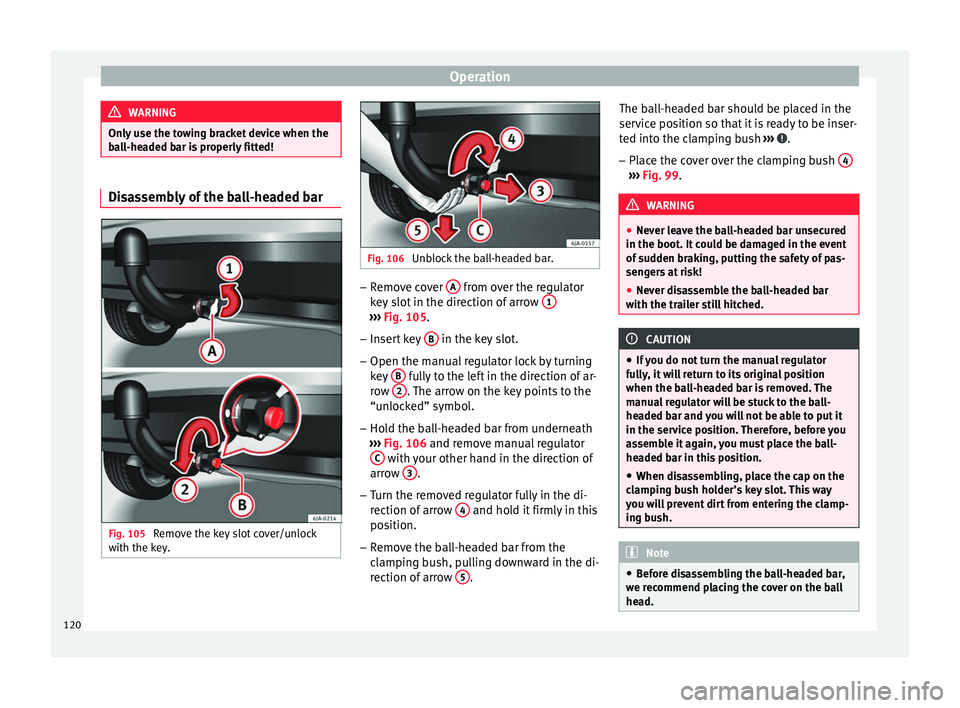
Fig. 105
Remove the key slot cover/unlock
with the key. Fig. 106
Unblock the ball-headed bar. –
Remove cover A from over the regulator
key slot in the direction of arrow 1 ›››
Fig. 105 .
– Inser
t key B in the key slot.
– Open the manual regulator lock by turning
key B fully to the left in the direction of ar-
row 2 . The arrow on the key points to the
“unlocked” symbol.
– Hold the ball-headed bar from underneath
››› Fig. 106 and remove manual regulator
C with your other hand in the direction of
arrow 3 .
– Turn the removed regulator fully in the di-
rection of arrow 4 and hold it firmly in this
position.
– Remove the ball-headed bar from the
clamping bush, pulling downward in the di-
rection of arrow 5 .The ball-headed bar should be placed in the
service position so that it is ready to be inser-
ted into the clamping bush
››› .
– Place the cover over the clamping bush 4 ›››
Fig. 99 . WARNING
● Never leave the ball-headed bar unsecured
in the boot. It could be damaged in the event
of sudden braking, putting the safety of pas-
sengers at risk!
● Never disassemble the ball-headed bar
with the trailer still hitched. CAUTION
● If you do not turn the manual regulator
fully, it will return to its original position
when the ball-headed bar is removed. The
manual regulator will be stuck to the ball-
headed bar and you will not be able to put it
in the service position. Therefore, before you
assemble it again, you must place the ball-
headed bar in this position.
● When disassembling, place the cap on the
clamping bush holder’s key slot. This way
you will prevent dirt from entering the clamp-
ing bush. Note
● Before disassembling the ball-headed bar,
we recommend placing the cover on the ball
head. 120
Page 123 of 200

Towing bracket device
●
Clean the ball-headed bar thoroughly be-
fore returning it to the on-board toolbox. Use and maintenance
Cover the clamping bush with the cap to pre-
vent dirt from entering.
Before hooking on the trailer, check the ball
head and, if necessary, lubricate it with ade-
quate lubricant.
Place the protective cover over the ball head
when storing the bar. This way, you will avoid
getting the boot dirty.
If it gets dirty, clean and dry the clamping
bush thoroughly with an appropriate prod-
uct.
CAUTION
The top part of the clamping bush opening is
lubricated. Be careful not to remove this lu-
brication. 121Technical specifications
Advice
Operation
Safety
Page 157 of 200

Emergencies
●
Do not drive faster than 80 km/h (50 mph).
● Avoid heavy acceleration, hard braking and
fast cornering.
● Check the tyre pressure after 10 minutes of
driving!
● The sealant is harmful to health and must
be immediately rinsed from affected skin. For the sake of the environment
Used or out-of-date sealant must be disposed
of in line with environmental protection regu-
lations. Note
● Observe the usage instructions provided by
the snow chain manufacturer.
● A new can of sealant can be acquired from
the selection of SEAT Original Accessories.
● Change the tyre repaired using the Tyre
Mobility System as soon as possible or ask
an official service about the possibility of re-
pairing it for you. Components of the Tyre Mobility
System*
Fig. 128
Contents of the Tyre Mobility System. The Tyre Mobility System contains the follow-
ing components:
An adapter to fit and remove the valve
Sticker indicating the speed: “max. 80
km/h” or “max. 50 mph”
Flexible filling hose with cap
Compressor
Flexible tyre inflating hose
Tyre pressure gauge
Air release screw
ON/OFF button
12 V cable connector ››› page 79
Can of sealant
1 2
3
4
5
6
7
8
9
10 Spare valve
The valve extractor 1
››› Fig. 128 has a slot
in its lo
wer end that fits onto the valve insert.
This is used to remove the valve insert from
the tyre and to replace it. This is also valid for
the spare valve insert 11 .
Work prior to using the Tyre Mobility
System The following jobs must be performed before
using the Tyre Mobility System:
– If you have a flat tyre, stop the vehicle well
away from moving traffic. Stop on flat, solid
ground.
– All vehicle occupants should leave the ve-
hicle . Vehicle occupants should wait in a
s af
e place (e.g. behind the roadside crash
barrier) while the wheel is being changed.
– Switch off the ignition and engage neutral
or move the selector lever on the automatic
g
earbox to position P.
– Apply the handbrake firmly.
– Check
whether the tyre can be repaired us-
ing the Tyre Mobility System ›››
page 154.
– If towing a trailer, unhitch it.
– Remove the Tyre Mobility System from the
boot
. »
11
155
Technical specifications
Advice
Operation
Safety
Page 161 of 200

Emergencies
on battery). Failure to comply could result in
an explosion.
●
Never use jump leads when one of the bat-
teries is frozen. Danger of explosion! Even af-
ter the battery has thawed, battery acid could
leak and cause chemical burns. If a battery
freezes, it should be replaced.
● Keep sparks, flames and lighted cigarettes
away from batteries, danger of explosion.
Failure to comply could result in an explo-
sion.
● Observe the instructions provided by the
manufacturer of the jump leads.
● Do not connect the negative cable from the
other vehicle directly to the negative terminal
of the flat battery. The gas emitted from the
battery could be ignited by sparks. Danger of
explosion.
● Do not attach the negative cable from the
other vehicle to parts of the fuel system or to
the brake line.
● The non-insulated parts of the battery
clamps must not be allowed to touch. The
jump lead attached to the positive battery
terminal must not touch metal parts of the ve-
hicle, this can cause a short circuit.
● Position the leads in such a way that they
cannot come into contact with any moving
parts in the engine compartment.
● Do not lean on the batteries. This could re-
sult in chemical burns. Note
The vehicles must not touch each other, oth-
erwise electricity could flow as soon as the
positive terminals are connected. Towing the vehicle
Introduction Vehicles with manual gearbox can be towed
using a towbar or towrope. They can also be
towed with either the front or rear wheels lif-
ted off the road.
Vehicles with automatic gearbox can be tow-
ed using a towbar or towrope. They can also
be towed with the front wheels lifted off the
road. If the vehicle is towed with the rear
wheels lifted off the road the automatic gear-
box will be damaged!
It is safer to tow a vehicle with a
towbar. A
towrope should only be used if you do not
h av
e a towbar.
Follow the instructions below when towing a
vehicle:
Notes for the driver of the towing vehicle
– Engage the clutch very gently when starting
to move or on vehicles with automatic gear-
box press the accelerator carefully. –
On vehicles with a manual gearbox, the
towrope must be taut before driving off.
Maximum towing speed is 50 km/h (31
mph).
Note
s for the driver of the towed vehicle
– The ignition should be switched on so that
the steering wheel lock is not engaged and
the turn signals, horn and windscreen wip-
ers and washers can be used.
– Put the gear lever in neutral or move the se-
lector lever to position N (automatic gear-
bo
x).
The brake servo and power steering only
work when the engine is running. Considera-
bly more effort is required on the brake pedal
and steering wheel when the engine is
switched off.
Ensure the towrope remains taut at all times
when towing. CAUTION
● Do not tow-start the engine. Risk of engine
damage! In vehicles with a catalytic convert-
er, fuel that has not been burned could reach
the catalytic converter and catch fire in it.
This could damage and destroy the catalytic
converter. You may use the battery from an-
other vehicle to help you start your engine
››› page 158.
» 159
Technical specifications
Advice
Operation
Safety
Page 162 of 200

Advice
●
If, due to a fault, there is no oil in the gear-
box, the car may only be towed with the
driven wheels lifted clear of the road and
transported on a special vehicle transporter
or trailer.
● If normal towing is not possible or if the ve-
hicle is to be towed for further than 50 km,
the vehicle must be transported on a special
vehicle transporter or trailer.
● The towrope should be slightly elastic to
reduce the load on both vehicles during tow-
ing. It is advisable to use a towrope made of
synthetic fibre or similar material only.
● Do not pull too hard with the towing vehicle
and always take care to avoid jerking the tow-
rope. When towing on a loose surface there is
always a risk of overloading and damaging
the anchorage points.
● Attach the towrope or towbar only to the
towline anchorages or to the removable tow-
ing bracket ››› page 114, or ››› page 161. Note
● We recommend you use the towrope or tow-
bar available in the SEAT Original Accessories
programme from authorised SEAT dealers.
● Towing a vehicle requires a certain degree
of practical skill. Both drivers should be fa-
miliar with the technique required for towing.
Inexperienced drivers should not attempt to
tow away another vehicle or to have their ve-
hicle towed. ●
Note the legal regulations concerning tow-
ing, particularly those regarding the signal-
ling of the towed and towing vehicle.
● The towrope must not be twisted, as under
certain circumstances this could unscrew the
front towline anchorage. Towline anchorage
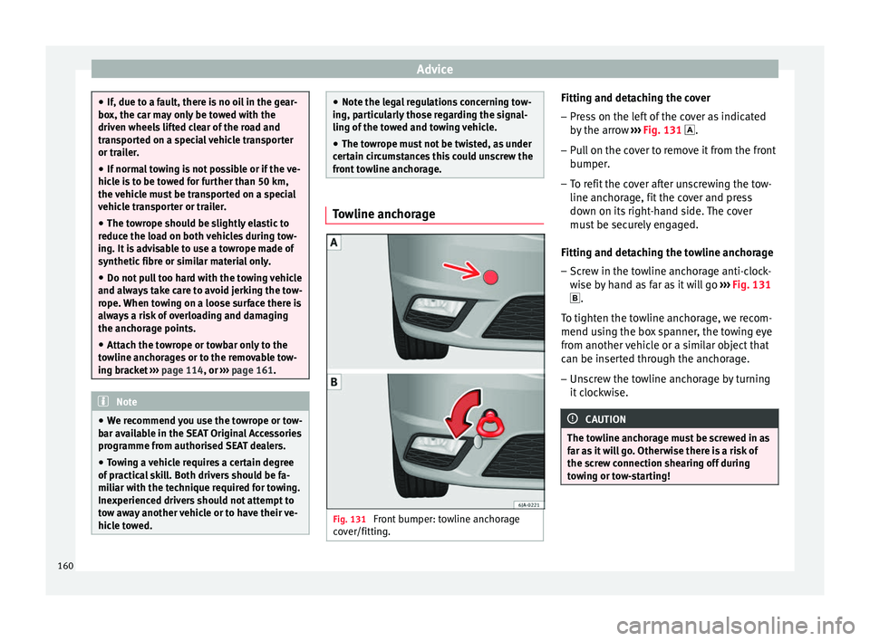
Fig. 131
Front bumper: towline anchorage
cover/fitting. Fitting and detaching the cover
– Press on the left of the cover as indicated
by the arrow ››› Fig. 131 .
– Pull on the cover to remove it from the front
bumper.
– To refit the cover after unscrewing the tow-
line anchorage, fit the cover and press
down on its right-hand side. The cover
must be securely engaged.
Fitting and detaching the towline anchorage
– Screw in the towline anchorage anti-clock-
wise by hand as far as it will go ››› Fig. 131
.
To tighten the towline anchorage, we recom-
mend using the box spanner, the towing eye
from another vehicle or a similar object that
can be inserted through the anchorage.
– Unscrew the towline anchorage by turning
it clockwise. CAUTION
The towline anchorage must be screwed in as
far as it will go. Otherwise there is a risk of
the screw connection shearing off during
towing or tow-starting! 160