clock Seat Toledo 2017 User Guide
[x] Cancel search | Manufacturer: SEAT, Model Year: 2017, Model line: Toledo, Model: Seat Toledo 2017Pages: 248, PDF Size: 5.86 MB
Page 92 of 248
Emergencies
Position of the bulbs››› Fig. 101Bulb function
ATurn signals: PY21W NA LL
BSide lights-brake lights: P21/5W
CSide lights: P21/5W Note
Check the condition of the seal. If damaged, a
repl
acement can be acquired from an Official
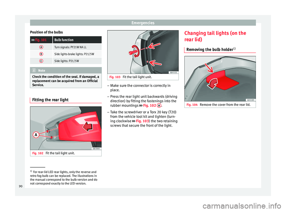
Service. Fitting the rear light
Fig. 102
Fit the tail light unit. Fig. 103
Fit the tail light unit. –
Make sure the connector is correctly in
pl
ac
e.
– Press the rear light unit backwards (driving
direction) by
fitting the fastenings into the
rubber mountings ››› Fig. 102 A .
– Take the screwdriver or a Torx 20 key (T20)
from the
v
ehicle tool kit and tighten (turn-
ing clockwise ››› Fig. 103) the two retaining
screws that secure the front of the light. Changing tail lights (on the
rear lid)
R
emoving the bulb holder 1) Fig. 104
Remove the cover from the rear lid. 1)
For rear-lid LED rear lights, only the reverse and
retr o f
og bulb can be replaced. The illustrations in
the manual correspond to the bulb version and do
not correspond exactly to the LED version.
90
Page 93 of 248
Fuses and bulbs
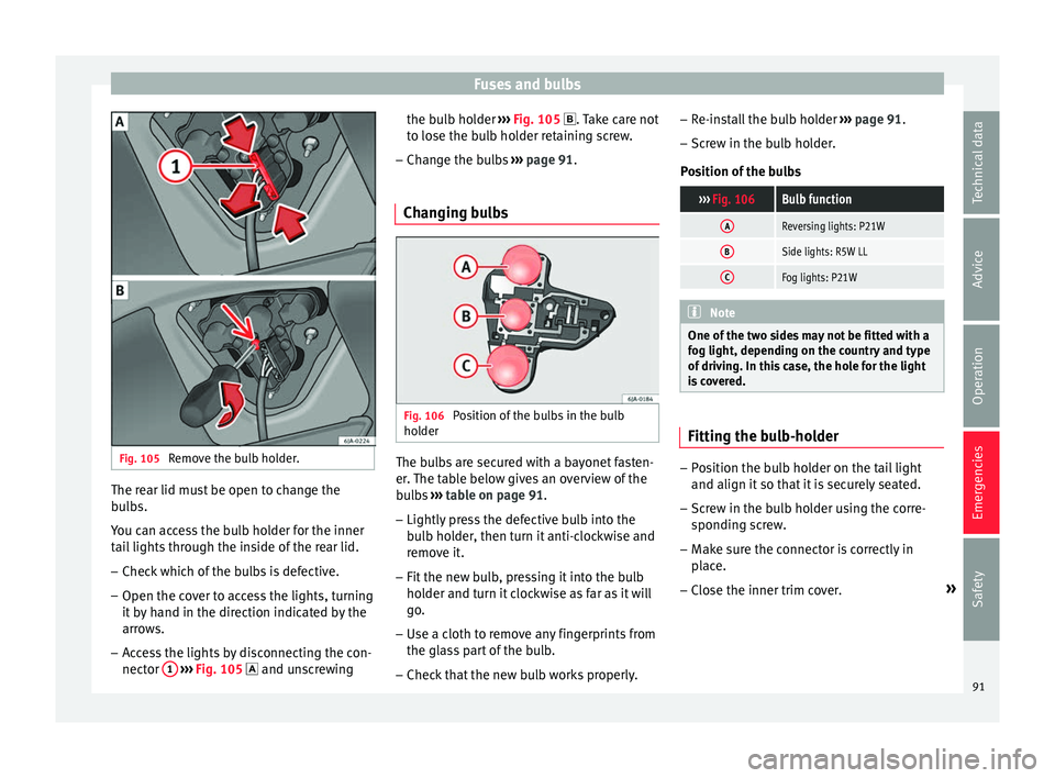
Fig. 105
Remove the bulb holder. The rear lid must be open to change the
b
u
l
bs.
You can access the bulb holder for the inner
tail lights through the inside of the rear lid.
– Check which of the bulbs is defective.
– Open the cover to access the lights, turning
it by
hand in the direction indicated by the
arrows.
– Access the lights by disconnecting the con-
nector 1
› ›
› Fig. 105
and unscrewing the bulb holder
›››
Fig. 105 . Take care not
to lose the bulb holder retaining screw.
– Change the bulbs ›››
page 91.
Changing bulbs Fig. 106
Position of the bulbs in the bulb
ho l
der The bulbs are secured with a bayonet fasten-
er
.
The t
able below gives an overview of the
bulbs ››› table on page 91.
– Lightly press the defective bulb into the
bul
b holder, then turn it anti-clockwise and
remove it.
– Fit the new bulb, pressing it into the bulb
holder and t
urn it clockwise as far as it will
go.
– Use a cloth to remove any fingerprints from
the glas
s part of the bulb.
– Check that the new bulb works properly. –
Re-ins
tall the bulb holder ››› page 91.
– Screw in the bulb holder.
Pos
ition of the bulbs
››› Fig. 106Bulb function
AReversing lights: P21W
BSide lights: R5W LL
CFog lights: P21W Note
One of the two sides may not be fitted with a
fog light, depending on the c
ountry and type
of driving. In this case, the hole for the light
is covered. Fitting the bulb-holder
–
Position the bulb holder on the tail light
and align it so th
at
it is securely seated.
– Screw in the bulb holder using the corre-
sponding s
crew.
– Make sure the connector is correctly in
plac
e.
– Close the inner trim cover. »
91
Technical data
Advice
Operation
Emergencies
Safety
Page 150 of 248
Operation
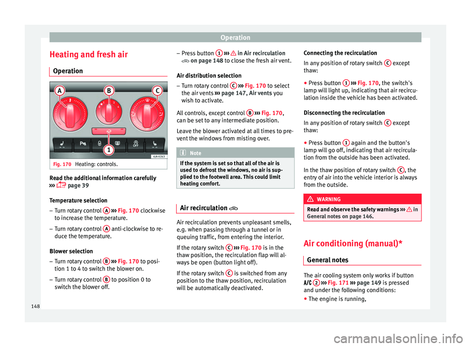
Heating and fresh air Oper ation Fig. 170
Heating: controls. Read the additional information carefully
› ›
›
page 39
Temperature selection
– Turn rotary control A
› ›
› Fig. 170
clockwise
to increase the temperature.
– Turn rotary control A anti-clockwise to re-
duc e the t
emper
ature.
Blower selection
– Turn rotary control B
› ›
› Fig. 170
to posi-
tion 1 to 4 to switch the blower on.
– Turn rotary control B to position 0 to
sw it
c
h the blower off. –
Pres
s button 1
› ›› in Air recirculation
on p ag
e 148
to close the fresh air vent.
Air distribution selection – Turn rotary control C
› ››
Fig. 170
t
o select
the air vents ››› page 147, Air vents you
wish to activate.
All controls, except control B
› ››
Fig. 170
,
c
an be set to any intermediate position.
Leave the blower activated at all times to pre-
vent the windows from misting over. Note
If the system is set so that all of the air is
used t o defr
ost the windows, no air is sup-
plied to the footwell area. This could limit
heating comfort. Air recirculation
Air recirculation prevents unpleasant smells,
e.
g. when p
a
ssing through a tunnel or in
queuing traffic, from entering the interior.
If the rotary switch C
› ›
›
Fig. 170 is in the
thaw position, the recirculation flap will al-
ways be open (button light off).
If the rotary switch C is switched from any
po sition t
o the thaw position, recirculation
will be automatically deactivated. Connecting the recirculation
In any po
sition of rotary switch C except
th a
w:
● Pr
ess button 1
› ››
Fig. 170
, the sw
itch's
lamp will light up, indicating that air recircu-
lation inside the vehicle has been activated.
Disconnecting the recirculation
In any position of rotary switch C except
th a
w:
● Pr
ess button 1 again and the button's
l amp w
i
ll go off, indicating that air recircula-
tion from the outside has been activated.
In the thaw position of rotary switch C , the
entr y
of
air into the vehicle interior is always
from the outside. WARNING
Read and observe the safety warnings ›››
in
Genera l
notes on page 146. Air conditioning (manual)*
Gener a
l
notes The air cooling system only works if button
2
› ›
›
Fig. 171 ›››
page 149 is pressed
and under the following conditions:
● The engine is running,
148
Page 151 of 248
Air conditioning
● The outs ide t
emper
ature is above +2°C
(+36°F),
● The blower control is in position 1–4.
When the coolin
g system is on and under cer-
tain conditions, air can be blown from the
vents at a temperature of approximately +5°C
(+41°F). In the event of prolonged, irregular
distribution of the air flow from the outlets
and significant differences in temperature,
e.g. on leaving the vehicle, sensitive people
may catch cold. Note
A visit to the specialised service once a year
is r
ecommended to clean the air conditioning
system. Manual operation
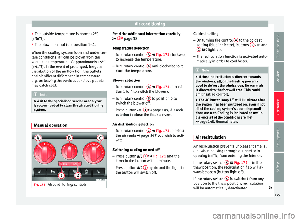
Fig. 171
Air conditioning: controls. Read the additional information carefully
› ›
›
page 38
Temperature selection – Turn rotary control A
› ››
Fig. 171
c
lockwise
to increase the temperature.
– Turn rotary control A anti-clockwise to re-
duc e the t
emper
ature.
Blower selection
– Turn rotary control B
› ››
Fig. 171
t
o posi-
tion 1 to 4 to switch the blower on.
– Turn rotary control B to position 0 to
sw it
c
h the blower off.
– Press button 1
› ›
› p
age 149, Air recir-
culation to close the fresh air vent.
Air distribution selection – Turn rotary control C
› ›
› Fig. 171
to select
the air vents ››› page 147 you wish to acti-
vate.
Switching cooling on and off
– Press button 2
› ›
› Fig. 171
and the
lamp in the button will illuminate.
– Press button 2 again and the light in
the b utt
on w
ill switch off. Coldest setting
– On turning the control A to the coldest
settin g (b
lue indic
ator), buttons 1 and
2
light up.
– The r ec
irculation function is activated auto-
matical
ly in order to cool faster. Note
● If the air di s
tribution is directed towards
the windows, all, of the heating power is
used to defrost the windscreen. No warm air
is directed to the footwell area. This could
limit heating comfort.
● The AC button lamp w
ill illuminate after
the system has been switched on, even if not
all of the cooling system's operating condi-
tions are met. Cooling is indicated as availa-
ble once all of the conditions are met
››› page 148, General notes . Air recirculation
Air recirculation prevents unpleasant smells,
e.
g. when p
a
ssing through a tunnel or in
queuing traffic, from entering the interior.
If the rotary switch C
› ›
›
Fig. 171 is in the
thaw position, the recirculation flap will al-
ways be open (button light off).
If the rotary switch C is switched from any
po sition t
o the thaw position, recirculation
will be automatically deactivated. »
149
Technical data
Advice
Operation
Emergencies
Safety
Page 154 of 248
Operation
In the event of prolonged, irregular distribu-
tion of the air flo
w fr
om the outlets (particu-
larly the footwells) and significant differen-
ces in temperature, e.g. on leaving the vehi-
cle, sensitive people may catch cold.
Air recirculation Air recirculation prevents unpleasant smells,
e.g. when p
a
ssing through a tunnel or in
queuing traffic, from entering the interior.
Switching on air recirculation mode
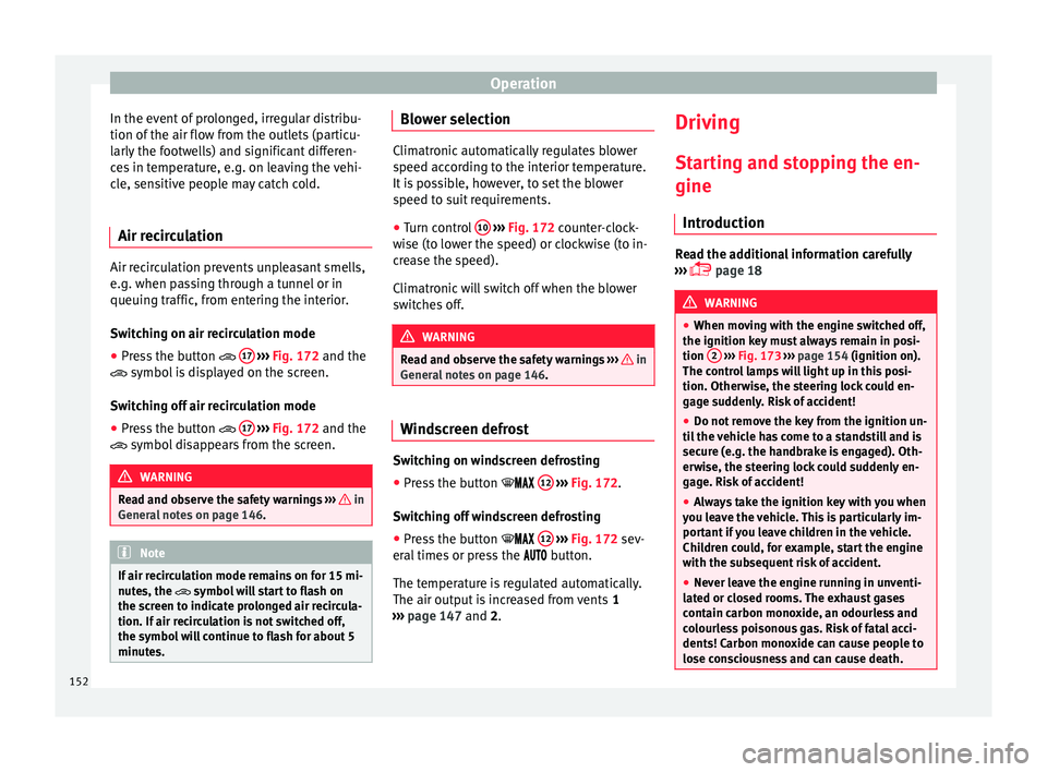
● Press the button 17
› ›
› Fig. 172
and the
symbol is displayed on the screen.
Switching off air recirculation mode
● Press the button 17
› ›
› Fig. 172
and the
symbol disappears from the screen. WARNING
Read and observe the safety warnings ›››
in
Genera l
notes on page 146. Note
If air recirculation mode remains on for 15 mi-
nute s, the
symbol will start to flash on
the screen to indicate prolonged air recircula-
tion. If air recirculation is not switched off,
the symbol will continue to flash for about 5
minutes. Blower selection
Climatronic automatically regulates blower
speed ac
c
ording to the interior temperature.
It is possible, however, to set the blower
speed to suit requirements.
● Turn control 10
››› Fig. 172 c
ounter-clock-
wise (to lower the speed) or clockwise (to in-
crease the speed).
Climatronic will switch off when the blower
switches off. WARNING
Read and observe the safety warnings ›››
in
Genera l
notes on page 146. Windscreen defrost
Switching on windscreen defrosting
●
Press the button
12
› ›
›
Fig. 172.
Switching off windscreen defrosting
● Press the button 12
› ›
›
Fig. 172 sev-
eral times or press the button.
The temperature is regulated automatically.
The air output is increased from vents 1
››› page 147 and 2. Driving
St ar
tin
g and stopping the en-
gine
Introduction Read the additional information carefully
›› ›
page 18 WARNING
● When mov in
g with the engine switched off,
the ignition key must always remain in posi-
tion 2
››› Fig. 173 ›
›› page 154 (ignition on).
The control lamps will light up in this posi-
tion. Otherwise, the steering lock could en-
gage suddenly. Risk of accident!
● Do not remove the key from the ignition un-
til the
vehicle has come to a standstill and is
secure (e.g. the handbrake is engaged). Oth-
erwise, the steering lock could suddenly en-
gage. Risk of accident!
● Always take the ignition key with you when
you le
ave the vehicle. This is particularly im-
portant if you leave children in the vehicle.
Children could, for example, start the engine
with the subsequent risk of accident.
● Never leave the engine running in unventi-
lated or c
losed rooms. The exhaust gases
contain carbon monoxide, an odourless and
colourless poisonous gas. Risk of fatal acci-
dents! Carbon monoxide can cause people to
lose consciousness and can cause death. 152
Page 203 of 248
Checking and refilling levels
Check the condition of all seat belts at regu-
l ar int
er
vals.
Very soiled belts may not retract properly. WARNING
● The seat belt
s should never be removed
from the vehicle for cleaning.
● Never clean using chemical products, as
chemica
l detergents destroy the fabric. En-
sure that the seat belts do not come into con-
tact with corrosive fluids such as acids, etc.
● If you find any damage to the belt webbing,
belt fitting
s, the belt retractor or the buckle,
the belt in question must be replaced by an
Official Service.
● Make sure that the inertia reel seat belts
are comp
letely dry before allowing them to
retract. Checking and refilling levels
F uel
R ef
uelling Fig. 202
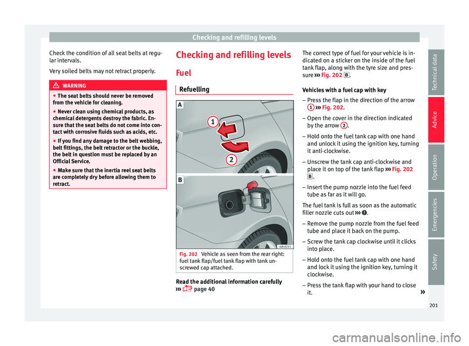
Vehicle as seen from the rear right:
f uel t
ank flap/fuel tank flap with tank un-
screwed cap attached. Read the additional information carefully
› ›
›
page 40 The correct type of fuel for your vehicle is in-
dicated on a s
ticker on the inside of the fuel
tank flap, along with the tyre size and pres-
sure ››› Fig. 202 .
Vehicles with a fuel cap with key
– Press the flap in the direction of the arrow
1
› ››
Fig. 202
.
– Open the c
over in the direction indicated
by the arr
ow 2 .
– Hold onto the fuel tank cap with one hand
and u n
loc
k it using the ignition key, turning
it anti-clockwise.
– Unscrew the tank cap anti-clockwise and
plac
e it on top of the tank flap ››› Fig. 202
.
– Insert the pump nozzle into the fuel feed
tube as
far as it will go.
The fuel tank is full as soon as the automatic
filler nozzle cuts out ››› .
– Remove the pump nozzle from the fuel feed
tube and p
l
ace it back on the pump.
– Screw the tank cap clockwise until it clicks
into pl
ace.
– Hold onto the fuel tank cap with one hand
and lock it
using the ignition key, turning it
clockwise.
– Press the tank flap with your hand to close
it. »
201
Technical data
Advice
Operation
Emergencies
Safety
Page 204 of 248
Advice
– Chec k
th
at the fuel flap is correctly closed.
Vehicles with a keyless fuel cap (the side
flap will unlock using the central locking sys-
tem)
– Once the vehicle has been unlocked using
the central
locking button, press the fuel
flap in the direction of the arrow 1›››
Fig. 202.
– Open the cover in the direction indicated
by
the arr
ow 2 .
– Unscrew the tank cap anti-clockwise and
pl
ac
e it on top of the tank flap ››› Fig. 202
.
– Insert the pump nozzle into the fuel feed
tube as
far as it will go.
The fuel tank is full as soon as the automatic
filler nozzle cuts out ››› .
– Remove the pump nozzle from the fuel feed
tube and p
l
ace it back on the pump.
– Screw the tank cap clockwise until it clicks
into pl
ace.
– Close the tank flap. Make sure you hear it
click
into place.
– Check that the fuel flap is properly closed. WARNING
Observe all relevant statutory regulations on
tran s
porting spare fuel canisters. For safety reasons, we do not recommend carrying a
sp
ar
e canister in the vehicle. The canister
could be damaged in an accident and fuel
may leak. Risk of fire! CAUTION
● Sw itc
h off the auxiliary heater (heater and
independent heater) before filling the tank.
● The fuel tank is full as soon as the automat-
ic fil
ler nozzle cuts out. Do not continue fill-
ing, as this will fill the expansion chamber.
● Never completely empty the tank! An irreg-
ular f
uel supply can cause ignition faults,
which can result in damage to a substantial
amount of engine parts and the exhaust sys-
tem.
● If any fuel is spilt onto the paintwork of the
vehicl
e, it should be removed immediately.
Risk of damage to paintwork! Note
There is no emergency mechanism for the
manua l
release of the fuel tank flap. If neces-
sary, request assistance from specialised per-
sonnel. Note
The fuel tank capacity is around 55 litres, of
which 7 litr e
s are the reserve. Types of petrol
The correct grade of petrol is listed inside the
fuel
t
ank flap.
The vehicle is equipped with a catalytic con-
verter and must only be run on unleaded pet-
rol. The petrol must comply with European
Standard EN 228 or German standard DIN
51626-1 and must be unleaded. You can re-
fuel with a maximum ethanol proportion of
10 % (E10). The types of petrol are differenti-
ated by their octane rating (RON).
The following titles appear on the corre-
sponding adhesive on the fuel tank flap:
Super unleaded 95 octane or normal 91 oc-
tane unleaded petrol
We recommend you use super 95 octane pet-
rol. If this is not available: normal 91 octane
petrol, with a slight decrease in power.
Super unleaded petrol with a minimum of 95
octanes
You should use super petrol with a minimum
of 95 octanes.
If super is not available, in an emergency you
may refuel with normal 91 octane petrol. In
this case only use moderate engine speeds
and a light throttle. Refuel with super as soon
as possible.
202
Page 218 of 248
Advice
“Fast-charging” a battery is dan
g erous and
requires a battery charger and special knowl-
edge. Fast charges should be performed by
an official technical service.
The battery caps should not be opened while
the battery is being charged. CAUTION
In vehicles fitted with the “Start-Stop” sys-
tem, the c h
arger cable cannot be directly con-
nected to the negative terminal of the vehicle
battery but must be attached to the engine
ground point ›››
page 53. Disconnecting and connecting the
b
att
er
y The following functions will either be inoper-
ativ
e or w
i
ll not work properly after discon-
necting and reconnecting the battery:
FunctionInstallation
Setting the clock››› page 97
The multifunction display data
is deleted››› page 99 Note
We recommend having the vehicle checked by
an authorised S EA
T dealer to guarantee the
correct working order of all electrical sys-
tems. Changing the battery
A replacement battery must have the same
cap
ac
ity, voltage, current rating and size as
the original. The appropriate types of battery
can be acquired from authorised SEAT deal-
ers.
We recommend having the battery changed
by an authorised SEAT dealer, where the new
battery will be correctly installed and the
original disposed of in line with regulations.
Automatic disconnection of electrical
equipment When heavily-charging a battery, the pro-
gr
amme sel
ect
ed by the electrical system
control unit prevents the battery from auto-
matically discharging. This may result in the
following:
● Increase in idling speed so that the alterna-
tor can s
upply more current to the electrical
system.
● The performance of certain electrical com-
ponents cou
ld be limited or some may switch
off temporarily, e.g. the heated seats, the
heated rear window, the 12 V power socket. Note
Despite any measures taken by the control
unit, the b att
ery could drain. e.g. with the en- gine is switched off, the key is turned in the
ignition for a lon
g period or the s
ide lights or
parking lights are switched on. The switching
off of certain electrical components does not
impair driving comfort and often the driver
will not even notice. 216
Page 239 of 248
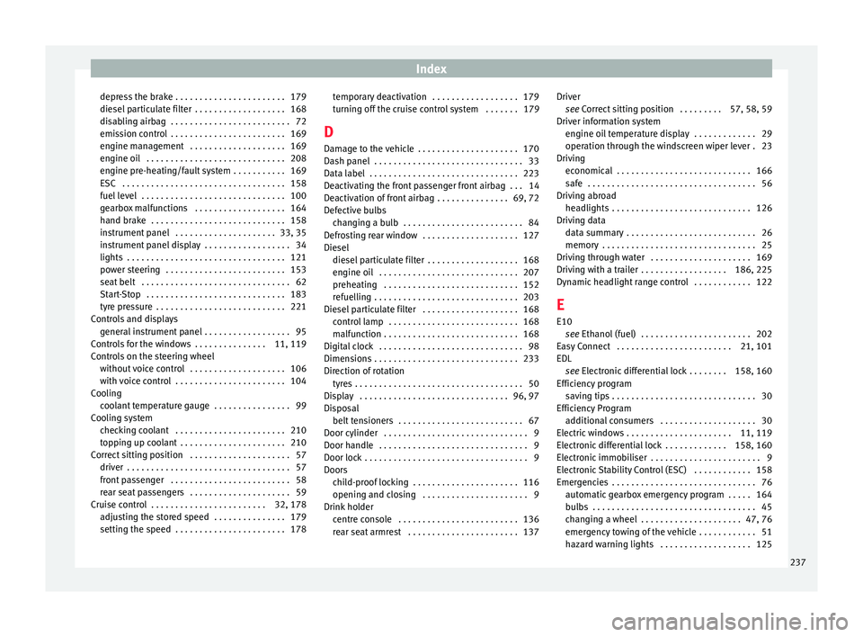
Index
depress the brake . . . . . . . . . . . . . . . . . . . . . . . 179
die sel
p
articulate filter . . . . . . . . . . . . . . . . . . . 168
disabling airbag . . . . . . . . . . . . . . . . . . . . . . . . . 72
emission control . . . . . . . . . . . . . . . . . . . . . . . . 169
engine management . . . . . . . . . . . . . . . . . . . . 169
engine oil . . . . . . . . . . . . . . . . . . . . . . . . . . . . . 208
engine pre-heating/fault system . . . . . . . . . . . 169
ESC . . . . . . . . . . . . . . . . . . . . . . . . . . . . . . . . . . 158
fuel level . . . . . . . . . . . . . . . . . . . . . . . . . . . . . . 100
gearbox malfunctions . . . . . . . . . . . . . . . . . . . 164
hand brake . . . . . . . . . . . . . . . . . . . . . . . . . . . . 158
instrument panel . . . . . . . . . . . . . . . . . . . . . 33, 35
instrument panel display . . . . . . . . . . . . . . . . . . 34
lights . . . . . . . . . . . . . . . . . . . . . . . . . . . . . . . . . 121
power steering . . . . . . . . . . . . . . . . . . . . . . . . . 153
seat belt . . . . . . . . . . . . . . . . . . . . . . . . . . . . . . . 62
Start-Stop . . . . . . . . . . . . . . . . . . . . . . . . . . . . . 183
tyre pressure . . . . . . . . . . . . . . . . . . . . . . . . . . . 221
Controls and displays general instrument panel . . . . . . . . . . . . . . . . . . 95
Controls for the windows . . . . . . . . . . . . . . . 11, 119
Controls on the steering wheel without voice control . . . . . . . . . . . . . . . . . . . . 106
with voice control . . . . . . . . . . . . . . . . . . . . . . . 104
Cooling coolant temperature gauge . . . . . . . . . . . . . . . . 99
Cooling system checking coolant . . . . . . . . . . . . . . . . . . . . . . . 210
topping up coolant . . . . . . . . . . . . . . . . . . . . . . 210
Correct sitting position . . . . . . . . . . . . . . . . . . . . . 57 driver . . . . . . . . . . . . . . . . . . . . . . . . . . . . . . . . . . 57
front passenger . . . . . . . . . . . . . . . . . . . . . . . . . 58
rear seat passengers . . . . . . . . . . . . . . . . . . . . . 59
Cruise control . . . . . . . . . . . . . . . . . . . . . . . . 32, 178 adjusting the stored speed . . . . . . . . . . . . . . . 179
setting the speed . . . . . . . . . . . . . . . . . . . . . . . 178 temporary deactivation . . . . . . . . . . . . . . . . . . 179
turning off
the cruise control system . . . . . . . 179
D Damage to the vehicle . . . . . . . . . . . . . . . . . . . . . 170
Dash panel . . . . . . . . . . . . . . . . . . . . . . . . . . . . . . . 33
Data label . . . . . . . . . . . . . . . . . . . . . . . . . . . . . . . 223
Deactivating the front passenger front airbag . . . 14
Deactivation of front airbag . . . . . . . . . . . . . . . 69, 72
Defective bulbs changing a bulb . . . . . . . . . . . . . . . . . . . . . . . . . 84
Defrosting rear window . . . . . . . . . . . . . . . . . . . . 127
Diesel diesel particulate filter . . . . . . . . . . . . . . . . . . . 168
engine oil . . . . . . . . . . . . . . . . . . . . . . . . . . . . . 207
preheating . . . . . . . . . . . . . . . . . . . . . . . . . . . . 152
refuelling . . . . . . . . . . . . . . . . . . . . . . . . . . . . . . 203
Diesel particulate filter . . . . . . . . . . . . . . . . . . . . 168 control lamp . . . . . . . . . . . . . . . . . . . . . . . . . . . 168
malfunction . . . . . . . . . . . . . . . . . . . . . . . . . . . . 168
Digital clock . . . . . . . . . . . . . . . . . . . . . . . . . . . . . . 98
Dimensions . . . . . . . . . . . . . . . . . . . . . . . . . . . . . . 233
Direction of rotation tyres . . . . . . . . . . . . . . . . . . . . . . . . . . . . . . . . . . . 50
Display . . . . . . . . . . . . . . . . . . . . . . . . . . . . . . . 96, 97
Disposal belt tensioners . . . . . . . . . . . . . . . . . . . . . . . . . . 67
Door cylinder . . . . . . . . . . . . . . . . . . . . . . . . . . . . . . 9
Door handle . . . . . . . . . . . . . . . . . . . . . . . . . . . . . . . 9
Door lock . . . . . . . . . . . . . . . . . . . . . . . . . . . . . . . . . . 9
Doors child-proof locking . . . . . . . . . . . . . . . . . . . . . . 116
opening and closing . . . . . . . . . . . . . . . . . . . . . . 9
Drink holder centre console . . . . . . . . . . . . . . . . . . . . . . . . . 136
rear seat armrest . . . . . . . . . . . . . . . . . . . . . . . 137 Driver
see Correct sitting position . . . . . . . . . 57, 58, 59
Driver information system engine oil temperature display . . . . . . . . . . . . . 29
operation through the windscreen wiper lever . 23
Driving economical . . . . . . . . . . . . . . . . . . . . . . . . . . . . 166
safe . . . . . . . . . . . . . . . . . . . . . . . . . . . . . . . . . . . 56
Driving abroad headlights . . . . . . . . . . . . . . . . . . . . . . . . . . . . . 126
Driving data data summary . . . . . . . . . . . . . . . . . . . . . . . . . . . 26
memory . . . . . . . . . . . . . . . . . . . . . . . . . . . . . . . . 25
Driving through water . . . . . . . . . . . . . . . . . . . . . 169
Driving with a trailer . . . . . . . . . . . . . . . . . . 186, 225
Dynamic headlight range control . . . . . . . . . . . . 122
E
E10 see Ethanol (fuel) . . . . . . . . . . . . . . . . . . . . . . . 202
Easy Connect . . . . . . . . . . . . . . . . . . . . . . . . 21, 101
EDL see Electronic differential lock . . . . . . . . 158, 160
Efficiency program saving tips . . . . . . . . . . . . . . . . . . . . . . . . . . . . . . 30
Efficiency Program additional consumers . . . . . . . . . . . . . . . . . . . . 30
Electric windows . . . . . . . . . . . . . . . . . . . . . . 11, 119
Electronic differential lock . . . . . . . . . . . . . 158, 160
Electronic immobiliser . . . . . . . . . . . . . . . . . . . . . . . 9
Electronic Stability Control (ESC) . . . . . . . . . . . . 158
Emergencies . . . . . . . . . . . . . . . . . . . . . . . . . . . . . . 76 automatic gearbox emergency program . . . . . 164
bulbs . . . . . . . . . . . . . . . . . . . . . . . . . . . . . . . . . . 45
changing a wheel . . . . . . . . . . . . . . . . . . . . . 47, 76
emergency towing of the vehicle . . . . . . . . . . . . 51
hazard warning lights . . . . . . . . . . . . . . . . . . . 125
237