heating Seat Toledo 2017 Owner's manual
[x] Cancel search | Manufacturer: SEAT, Model Year: 2017, Model line: Toledo, Model: Seat Toledo 2017Pages: 248, PDF Size: 5.86 MB
Page 5 of 248
Table of Contents
Table of Contents
The e s
senti
als . . . . . . . . . . . . . . . . . . . . . . . . 5
Exterior view . . . . . . . . . . . . . . . . . . . . . . . . . . . . 5
Exterior view . . . . . . . . . . . . . . . . . . . . . . . . . . . . 6
Interior view (left-hand drive) . . . . . . . . . . . . . . 7
Interior view (right-hand drive) . . . . . . . . . . . . . 8
How it works . . . . . . . . . . . . . . . . . . . . . . . . . . . . 9
Unlocking and locking . . . . . . . . . . . . . . . . . . . . 9
Before driving . . . . . . . . . . . . . . . . . . . . . . . . . . . 11
Airbags . . . . . . . . . . . . . . . . . . . . . . . . . . . . . . . . 14
Child seats . . . . . . . . . . . . . . . . . . . . . . . . . . . . . 16
Starting the vehicle . . . . . . . . . . . . . . . . . . . . . . 18
Lights and visibility . . . . . . . . . . . . . . . . . . . . . . 18
Easy Connect . . . . . . . . . . . . . . . . . . . . . . . . . . . 21
Driver information System . . . . . . . . . . . . . . . . . 23
Status display . . . . . . . . . . . . . . . . . . . . . . . . . . . 28
Cruise control . . . . . . . . . . . . . . . . . . . . . . . . . . . 32
Warning lamps . . . . . . . . . . . . . . . . . . . . . . . . . . 33
Gearbox lever . . . . . . . . . . . . . . . . . . . . . . . . . . . 35
Air conditioning . . . . . . . . . . . . . . . . . . . . . . . . . 37
Fluid Level control . . . . . . . . . . . . . . . . . . . . . . . 40
Emergencies . . . . . . . . . . . . . . . . . . . . . . . . . . . . 44
Fuses . . . . . . . . . . . . . . . . . . . . . . . . . . . . . . . . . . 44
Bulbs . . . . . . . . . . . . . . . . . . . . . . . . . . . . . . . . . . 45
Action in the event of a puncture . . . . . . . . . . . 45
Changing a wheel . . . . . . . . . . . . . . . . . . . . . . . 47
Snow chains . . . . . . . . . . . . . . . . . . . . . . . . . . . . 50
Emergency towing of the vehicle . . . . . . . . . . . 51
How to jump start . . . . . . . . . . . . . . . . . . . . . . . . 52
Changing the windscreen wiper blades . . . . . . 54
Safety . . . . . . . . . . . . . . . . . . . . . . . . . . . . . . . . 56
Safe driving . . . . . . . . . . . . . . . . . . . . . . . . . . . . 56
Safety first! . . . . . . . . . . . . . . . . . . . . . . . . . . . . . 56
Advice about driving . . . . . . . . . . . . . . . . . . . . . 56 Correct position of the vehicle occupants . . . . 57
Pedal area . . . . . . . . . . . . . . . . . . . . . . . . . . . . . . 61
Seat belts
. . . . . . . . . . . . . . . . . . . . . . . . . . . . . . 62
The whys and wherefores of seat belts . . . . . . . 62
How to properly adjust your seatbelt . . . . . . . . 65
Seat belt tensioners . . . . . . . . . . . . . . . . . . . . . . 66
Airbag system . . . . . . . . . . . . . . . . . . . . . . . . . . 67
Brief introduction . . . . . . . . . . . . . . . . . . . . . . . . 67
Airbag safety instructions . . . . . . . . . . . . . . . . . 70
Deactivating airbags . . . . . . . . . . . . . . . . . . . . . 72
Transporting children safely . . . . . . . . . . . . . . . 73
Safety for children . . . . . . . . . . . . . . . . . . . . . . . 73
Child seats . . . . . . . . . . . . . . . . . . . . . . . . . . . . . 75
Emergencies . . . . . . . . . . . . . . . . . . . . . . . . . . 76
Self-help . . . . . . . . . . . . . . . . . . . . . . . . . . . . . . . 76
Emergency equipment . . . . . . . . . . . . . . . . . . . . 76
Changing a wheel . . . . . . . . . . . . . . . . . . . . . . . 76
Tyre repairs . . . . . . . . . . . . . . . . . . . . . . . . . . . . . 77
Towing the vehicle . . . . . . . . . . . . . . . . . . . . . . . 79
Fuses and bulbs . . . . . . . . . . . . . . . . . . . . . . . . . 81
Fuses . . . . . . . . . . . . . . . . . . . . . . . . . . . . . . . . . . 81
Changing bulbs . . . . . . . . . . . . . . . . . . . . . . . . . 84
Changing the fog light bulbs . . . . . . . . . . . . . . . 88
Changing the rear lights (on the side panel) . . 88
Changing tail lights (on the rear lid) . . . . . . . . . 90
Changing the bulb on the number plate . . . . . . 92
Side turn signals . . . . . . . . . . . . . . . . . . . . . . . . 92
Operation . . . . . . . . . . . . . . . . . . . . . . . . . . . . . 95
Controls and displays . . . . . . . . . . . . . . . . . . . . 95
General instrument panel . . . . . . . . . . . . . . . . . 94
Instruments and warning lamps . . . . . . . . . . . . 96
Instruments . . . . . . . . . . . . . . . . . . . . . . . . . . . . 96
Control lamps . . . . . . . . . . . . . . . . . . . . . . . . . . . 100
Introduction to the Easy Connect system* . . . . 101
System settings (CAR)* . . . . . . . . . . . . . . . . . . . 101 Communications and multimedia
. . . . . . . . . . . 103
Steering wheel controls* . . . . . . . . . . . . . . . . . . 103
Multimedia . . . . . . . . . . . . . . . . . . . . . . . . . . . . . 108
Opening and closing . . . . . . . . . . . . . . . . . . . . . 108
Remote control . . . . . . . . . . . . . . . . . . . . . . . . . . 108
Keys . . . . . . . . . . . . . . . . . . . . . . . . . . . . . . . . . . . 109
Central locking system . . . . . . . . . . . . . . . . . . . . 111
Anti-theft alarm* . . . . . . . . . . . . . . . . . . . . . . . . 116
Rear lid . . . . . . . . . . . . . . . . . . . . . . . . . . . . . . . . 118
Controls for the windows . . . . . . . . . . . . . . . . . . 119
Lights and visibility . . . . . . . . . . . . . . . . . . . . . . 120
Lights . . . . . . . . . . . . . . . . . . . . . . . . . . . . . . . . . 120
Interior lights . . . . . . . . . . . . . . . . . . . . . . . . . . . 126
Visibility . . . . . . . . . . . . . . . . . . . . . . . . . . . . . . . 127
Windscreen wipers and windscreen wash-
ers . . . . . . . . . . . . . . . . . . . . . . . . . . . . . . . . . . . . 128
Mirr
ors . . . . . . . . . . . . . . . . . . . . . . . . . . . . . . . . . 130
Seats and head restraints . . . . . . . . . . . . . . . . . 131
Adjusting seats and head restraints . . . . . . . . . 131
Seat functions . . . . . . . . . . . . . . . . . . . . . . . . . . 132
Transport and practical equipment . . . . . . . . . 135
Practical equipment . . . . . . . . . . . . . . . . . . . . . . 135
Storing objects . . . . . . . . . . . . . . . . . . . . . . . . . . 140
Luggage compartment . . . . . . . . . . . . . . . . . . . . 141
Roof rack* . . . . . . . . . . . . . . . . . . . . . . . . . . . . . . 144
Air conditioning . . . . . . . . . . . . . . . . . . . . . . . . . 146
Heating and air conditioning . . . . . . . . . . . . . . . 146
Heating and fresh air . . . . . . . . . . . . . . . . . . . . . 148
Air conditioning (manual)* . . . . . . . . . . . . . . . . 148
Climatronic* (automatic air conditioning) . . . . 150
Driving . . . . . . . . . . . . . . . . . . . . . . . . . . . . . . . . 152
Starting and stopping the engine . . . . . . . . . . . 152
Brakes and brake servo systems . . . . . . . . . . . . 156
Braking and stability systems . . . . . . . . . . . . . . 158
Manual gearbox . . . . . . . . . . . . . . . . . . . . . . . . . 160
Automatic gearbox . . . . . . . . . . . . . . . . . . . . . . . 160
Run-in and economical driving . . . . . . . . . . . . . 165
3
Page 20 of 248
The essentials
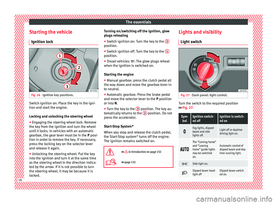
Starting the vehicle Ignition loc kFig. 26
Ignition key positions. Switch ignition on: Place the key in the igni-
tion and s
t
ar
t the engine.
Locking and unlocking the steering wheel
● Engaging the steering wheel lock: Remove
the key fr
om the ignition and turn the wheel
until it locks. In vehicles with an automatic
gearbox, the gear lever must be in the P posi-
tion in order to remove the key. If necessary,
press the locking key on the selector lever
and release it again.
● Unlocking the steering wheel: Put the key
into the ignition and turn it
at the same time
as the steering wheel in the direction indica-
ted by the arrow. If it is not possible to turn
the steering wheel, it may be because it is
locked. Turning on/switching off the ignition, glow
plugs
reheating
● Switch ignition on: Turn the key to the 2 position.
●
Switch ignition off. Turn the key to the 1 position.
●
Diesel vehicles : The glo
w p
lugs reheat
when the ignition is switched on.
Starting the engine
● Manual gearbox: press the clutch pedal all
the way
down and move the gearbox lever in-
to neutral.
● Automatic gearbox: Press the brake pedal
and move the sel
ector lever to the P position
or into N.
● Turn the key to the 3 position. The key au-
t om
atic
ally returns to the 2 position. Do not
pr e
s
s the accelerator.
Start-Stop System*
When you stop and release the clutch pedal,
the Start-Stop system* turns off the engine.
The ignition remains switched on.
››› in Introduction on page 152
››› page 152 Lights and visibility
Light sw
it
ch Fig. 27
Dash panel: light control. Turn the switch to the required position
› ›
›
Fig. 27.
Sym-
bolIgnition switch-
ed offIgnition is switch-
ed on
Fog lights, dipped
beam and side
lights off.Light off or daytime
driving light on.
The “Coming home”
and “Leaving
home” guide lights
may be switched
on.Automatic control of
dipped beam and day-
time running light.
Side light on.
Dipped beam head-
light offDipped beam switch-
ed on.
18
Page 36 of 248
The essentials
Yellow warning lamps Central warning lamp: additional
information on the instrument
panel display–
Front brake pads worn.›››
page
157
it lights up:
Fault in the ESC, or
disconnection caused by the sys-
tem.
››› page
158
flashes: ESC or ASR activated.
ASR manually deactivated.›››
page
158
ABS faulty or does not work.
Rear fog light switched on.›››
page 18
lights up or flashes:
fault in the
emission control system.››› page
167
it lights up:
pre-heating of diesel
engine.
››› page
169
flashes: fault in the diesel engine
management.
fault in the petrol engine man-
agement.›››
page
169
lights up or flashes:
fault in the
steering system.››› page
153
Tyre pressure too low, or fault in
the tyre pressure monitoring sys-
tem.›››
page
221
Fuel tank almost empty.›››
page
100
Fault in airbag system and seat
belt tensioners.›››
page
67 Other warning lamps
Left or right turn signal.›››
page 19
Hazard warning lights on.››› page
125
Trailer turn signals›››
page
186
it lights up:
Press the foot brake!
flashes: the selector lever locking
button has not engaged.››› page
163
it lights up:
cruise control activa-
ted or speed limiter switched on
and active.
››› page 32
flashes: the speed set by the
speed limiter has been exceeded.
Main beam on or flasher on.›››
page 19
››› in Control and warning lamps on
page 101
››› page 100 On the instrument panel display
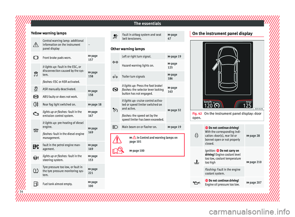
Fig. 42
On the instrument panel display: door
open.
Do not continue driving!
With the corresponding indi-
cation: door(s), rear lid or
bonnet open or not properly
closed.
››› page 28
Ignition: Do not carry on
driving! Engine coolant level
too low, coolant temperature
too high
››› page 210
Flashing: Fault in the engine
coolant system.
Do not continue driving!
Engine oil pressure too low.››› page 207 34
Page 40 of 248
The essentials
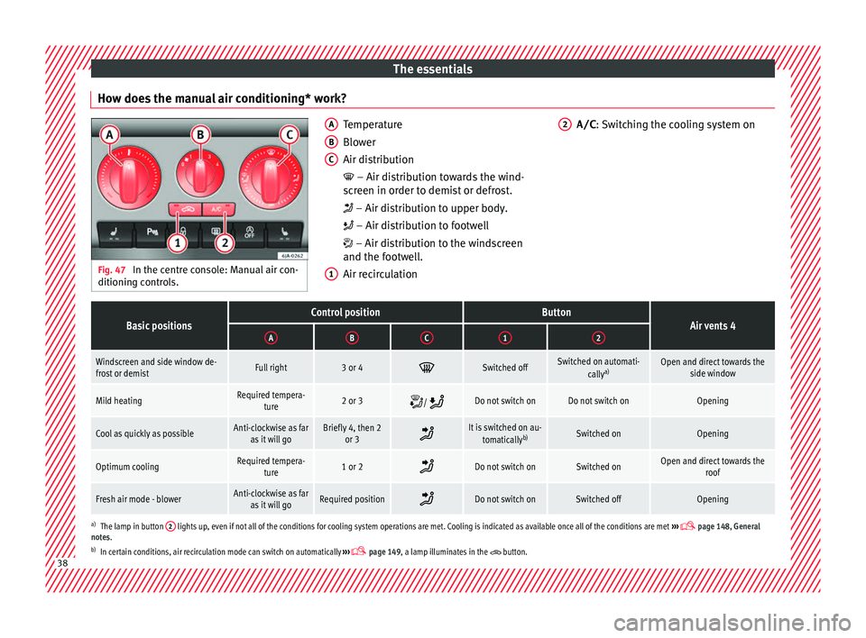
How does the manual air conditioning* work? Fig. 47
In the centre console: Manual air con-
ditioning c ontr
ols. Temperature
Blow
er
Air di
stribution
– Air distribution towards the wind-
screen in order to demist or defrost.
– Air distribution to upper body.
– Air distribution to footwell
– Air distribution to the windscreen
and the footwell.
Air recirculation
A B
C
1 A/C
: Switching the cooling system on
2
Basic positionsControl positionButtonAir vents 4ABC12
Windscreen and side window de-
frost or demistFull right3 or 4 Switched offSwitched on automati-
callya)Open and direct towards the
side window
Mild heatingRequired tempera-ture2 or 3 / Do not switch onDo not switch onOpening
Cool as quickly as possibleAnti-clockwise as far
as it will goBriefly 4, then 2 or 3 It is switched on au-
tomatically b)Switched onOpening
Optimum coolingRequired tempera-
ture1 or 2 Do not switch onSwitched onOpen and direct towards the
roof
Fresh air mode - blowerAnti-clockwise as faras it will goRequired position Do not switch onSwitched offOpening
a)
The lamp in button 2 lights up, even if not all of the conditions for cooling system operations are met. Cooling is indicated as available once all of the conditions are met
››› page 148, General
notes.
b) In certain conditions, air recirculation mode can switch on automatically ›››
page 149, a lamp illuminates in the button.38
Page 41 of 248
The essentials
››› in General notes on page 146
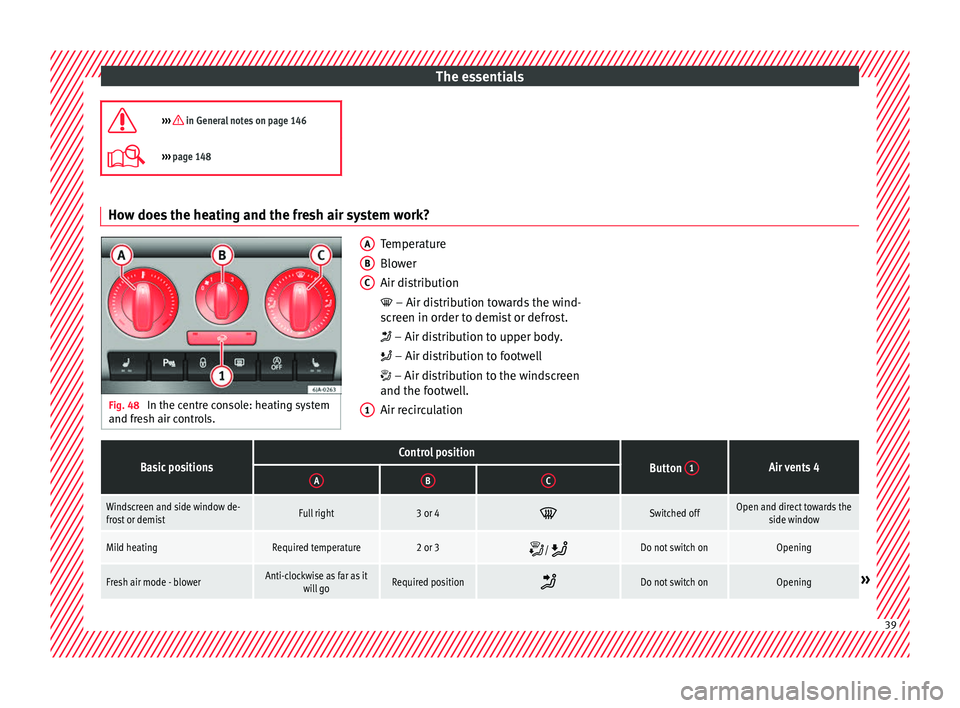
››› page 148 How does the heating and the fresh air system work?
Fig. 48
In the centre console: heating system
and fre sh air c
ontrols. Temperature
Blow
er
Air di
stribution
– Air distribution towards the wind-
screen in order to demist or defrost.
– Air distribution to upper body.
– Air distribution to footwell
– Air distribution to the windscreen
and the footwell.
Air recirculation
A B
C
1
Basic positionsControl positionButton
1Air vents 4ABC
Windscreen and side window de-
frost or demistFull right3 or 4 Switched offOpen and direct towards the
side window
Mild heatingRequired temperature2 or 3 / Do not switch onOpening
Fresh air mode - blowerAnti-clockwise as far as it
will goRequired position Do not switch onOpening»
39
Page 81 of 248
Self-help
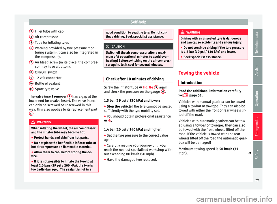
Filler tube with cap
Air c ompr
e
ssor
Tube for inflating tyres
Warning provided by tyre pressure moni-
toring system (it can also be integrated in
the compressor).
Air bleed screw (in its place, the compres-
sor may have a button).
ON/OFF switch
12 volt connector
Bottle of sealant
Spare tyre valve
The valve insert remover 1 has a gap at the
lo w
er end f
or a valve insert. The valve insert
can only be screwed or unscrewed in this
way. This also applies to its replacement part 11 .
WARNING
When inflating the wheel, the air compressor
and the inflat or t
ube may become hot.
● Protect hands and skin from hot parts.
● Do not place the hot flexible inflator tube or
hot air compr
essor on flammable material.
● Allow them to cool before storing the de-
vice.
● If
it is not possible to inflate the tyre to at
lea
st 2.0 bars (29 psi / 200 kPa), the tyre is
too badly damaged. The sealant is not in a 3
4
5
6
7
8
9
10
11 good condition to seal the tyre. Do not con-
tinue drivin
g.
Seek specialist assistance. CAUTION
Switch off the air compressor after a maxi-
mum of 8 operation
al minutes to avoid over-
heating! Before switching on the air compres-
sor again, let it cool for several minutes. Check after 10 minutes of driving
Screw the inflator tube
››
›
Fig. 84 5 again
and c hec
k
the pressure on the gauge 6 .
1.3 b ar (19 p
s
i / 130 kPa) and lower:
● Stop the vehicle! The tyre c
annot be sealed
sufficiently with the tyre mobility set.
● You should obtain professional assistance
›››
.
1.4 b ar (20 p
s
i / 140 kPa) and higher:
● Set the tyre pressure to the correct value
again.
● Car
efully resume your journey until you
reac
h the nearest specialised workshop with-
out exceeding 80 km/h (50 mph).
● Have the damaged tyre replaced. WARNING
Driving with an unsealed tyre is dangerous
and can c au
se accidents and serious injury.
● Do not continue driving if the tyre pressure
is 1.3
bar (19 psi / 130 kPa) and lower.
● Seek specialist assistance. Towing the vehicle
Introduction Read the additional information carefully
› ›
›
page 51.
Vehicles with manual gearbox can be towed
using a towbar or towrope. They can also be
towed with either the front or rear wheels lif-
ted off the road.
Vehicles with automatic gearbox can be tow-
ed using a towbar or towrope. They can also
be towed with the front wheels lifted off the
road. If the vehicle is towed with the rear
wheels lifted off the road the automatic gear-
box will be damaged!
Maximum towing speed is 50 km/h (31
mph). »
79
Technical data
Advice
Operation
Emergencies
Safety
Page 85 of 248
Fuses and bulbsNo.Consumer
24Air conditioning fan, heating, control unit for air
conditioning, heating
26Front seat heating switch.
27Rear window wiper
29Airbag
30
Electric windows, reversing light switch, air con-
ditioning control unit, Park Assist control unit,
exterior mirror, power supply for middle button
bar, power supply for the side button bar, interi-
or mirror
31Fuel pump, radiator fan control unit, cruise con-
trol, relay coil for the windscreen and rear win-
dow washer system, switch for the lights
32Diagnostics socket, headlight range regulator,
control lever under the steering wheel, ambient
lighting regulator
33Ignition relay coil, clutch pedal switch
34Heatable washer jets of windscreen washer
36USB charging socket
37Radar
39Additional electric heating
41Rear window heater
42Electric windows - passenger
43Towing bracket - Connector contact
No.Consumer
4412 V connection in the interior, 12 V connection
in the boot
45Rear right window
46Windshield and front window washing system,
control lever under the steering wheel
47Towing bracket - Connector contact
48Towing bracket - Right hand light
49Fuel pump control unit
50Radio
51Heat for exterior mirrors
52Keyless Access
53Steering lock (Keyless Access)
54ABS/ESC control unit
56Diagnosis
59Full LED
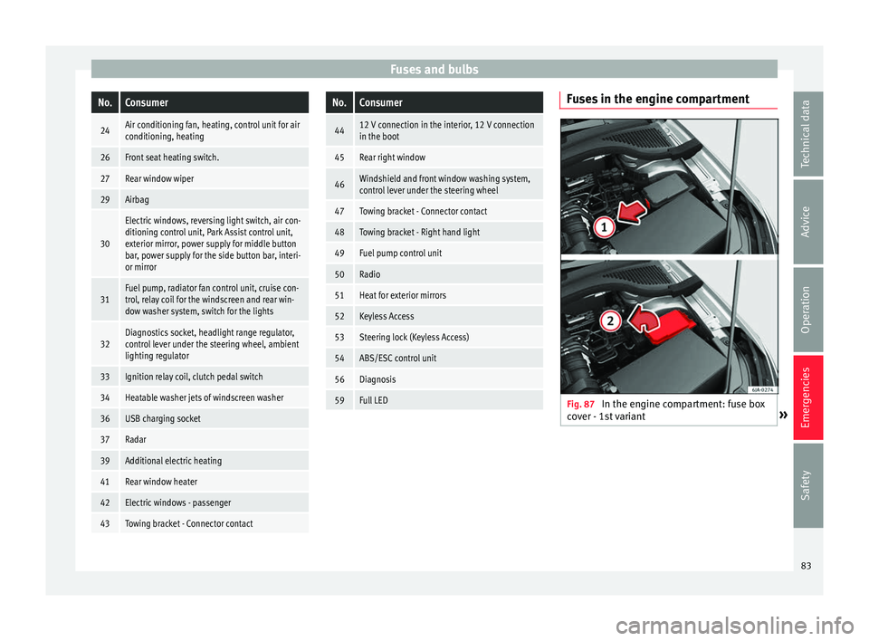
Fuses in the engine compartment
Fig. 87
In the engine compartment: fuse box
c o
v
er - 1st variant » 83
Technical data
Advice
Operation
Emergencies
Safety
Page 86 of 248
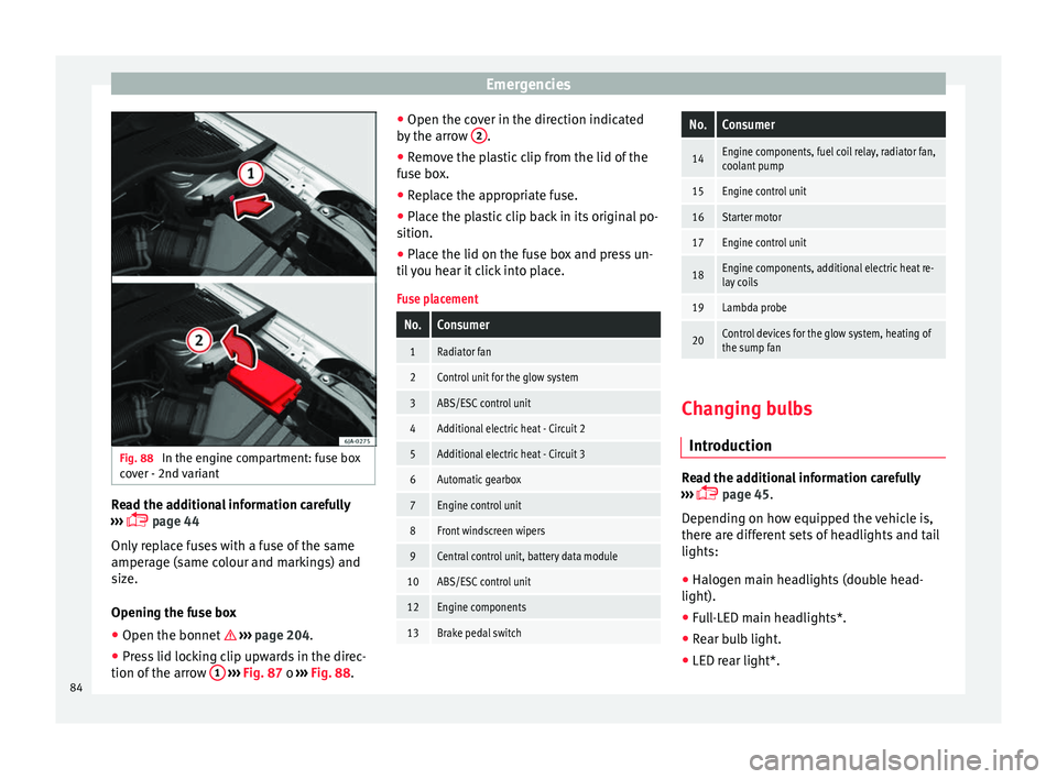
Emergencies
Fig. 88
In the engine compartment: fuse box
c o
v
er - 2nd variant Read the additional information carefully
› ›
›
page 44
Only replace fuses with a fuse of the same
amperage (same colour and markings) and
size.
Opening the fuse box ● Open the bonnet ›››
page 204.
● Press lid locking clip upwards in the direc-
tion of the arro
w 1
› ›
› Fig. 87 o ››› Fig. 88. ●
Open the cov
er in the direction indicated
by the arrow 2 .
● Remove the plastic clip from the lid of the
f u
se bo
x.
● Replace the appropriate fuse.
● Place the plastic clip back in its original po-
sition.
● Plac
e the lid on the fuse box and press un-
til
you hear it click into place.
Fuse placement
No.Consumer
1Radiator fan
2Control unit for the glow system
3ABS/ESC control unit
4Additional electric heat - Circuit 2
5Additional electric heat - Circuit 3
6Automatic gearbox
7Engine control unit
8Front windscreen wipers
9Central control unit, battery data module
10ABS/ESC control unit
12Engine components
13Brake pedal switch
No.Consumer
14Engine components, fuel coil relay, radiator fan,
coolant pump
15Engine control unit
16Starter motor
17Engine control unit
18Engine components, additional electric heat re-
lay coils
19Lambda probe
20Control devices for the glow system, heating of
the sump fan Changing bulbs
Intr oduction Read the additional information carefully
› ›
›
page 45.
Depending on how equipped the vehicle is,
there are different sets of headlights and tail
lights:
● Halogen main headlights (double head-
light).
● Full-LED main headlights*.
● Rear bulb light.
● LED rear light*.
84
Page 97 of 248
Controls and displays
Operation
C ontr
o
ls and displays
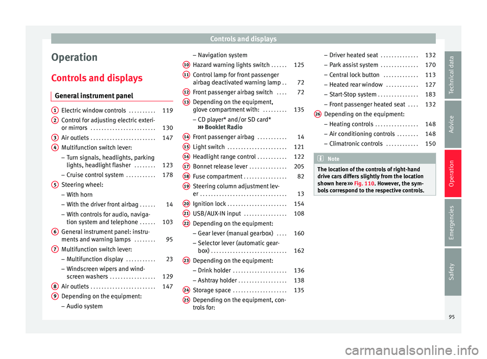
General instrument panel Electric window controls
. . . . . . . . . .119
Control for adjusting electric exteri-
or mirror s . . . . . . . . . . . . . . . . . . . . . . . . 130
Air outl
ets . . . . . . . . . . . . . . . . . . . . . . . . 147
Multifunction switch lever:
– Turn s ign
als, headlights, parking
lights, headlight flasher . . . . . . . .123
– Crui se c
ontrol system . . . . . . . . . . .178
Steering wheel:
– With horn
– With the driv
er front airbag . . . . . .14
– With c ontr
ols for audio, naviga-
tion system and telephone . . . . . .103
General instrument panel: instru-
ments and w arnin
g lamps . . . . . . . . 95
Multifunction switch lever:
– Multif
unction display . . . . . . . . . . .23
– Wind s
creen wipers and wind-
screen washers . . . . . . . . . . . . . . . . . 129
Air outlets . . . . . . . . . . . . . . . . . . . . . . . . 147
Depending on the equipment:
– Audio sy st
em
1 2
3
4
5
6
7
8
9 –
Nav ig
ation sy
stem
Hazard warning lights switch . . . . . .125
Control lamp for front passenger
airbag deactiv
ated warning lamp . .72
Front passenger airbag switch . . . .72
Depending on the equipment,
glove c
ompartment with: . . . . . . . . .135
– CD pla
yer* and/or SD card*
››› Booklet Radio
Front passenger airbag . . . . . . . . . . .14
Light switch . . . . . . . . . . . . . . . . . . . . . . 121
Headlight range control . . . . . . . . . . .122
Bonnet release lever . . . . . . . . . . . . . .205
Fuse compartment . . . . . . . . . . . . . . . . 82
Steering column adjustment lev-
er . . . . . . . . . . . . . . . . . . . . . . . . . . . . . . . . 13
Ignition lock . . . . . . . . . . . . . . . . . . . . . . 154
USB/AUX-IN input . . . . . . . . . . . . . . . . 108
Depending on the equipment: – Gear lev
er (manual gearbox) . . . .160
– Select or l
ever (automatic gear-
box) . . . . . . . . . . . . . . . . . . . . . . . . . . . . 162
Depending on the equipment:
– Drink ho l
der . . . . . . . . . . . . . . . . . . . . 136
– Ashtra y
holder . . . . . . . . . . . . . . . . . . 138
Storage space . . . . . . . . . . . . . . . . . . . . 135
Depending on the equipment, con-
tro l
s for:
10 11
12
13
14
15
16
17
18
19
20
21
22
23
24
25 –
Driv er he
at
ed seat . . . . . . . . . . . . . . 132
– Park a
ssist system . . . . . . . . . . . . . . 170
– Central
lock button . . . . . . . . . . . . . 113
– Heated r
ear window . . . . . . . . . . . . 127
– Start
-Stop system . . . . . . . . . . . . . . . 183
– Front p
assenger heated seat . . . .132
Depending on the equipment: – Heating c
ontrols . . . . . . . . . . . . . . . . 148
– Air conditioning c
ontrols . . . . . . . . 148
– Climatr
onic controls . . . . . . . . . . . . 150 Note
The location of the controls of right-hand
drive c ar
s differs slightly from the location
shown here ››› Fig. 110. However, the sym-
bols correspond to the respective controls. 26
95
Technical data
Advice
Operation
Emergencies
Safety
Page 102 of 248
Operation
Normal temperature
If in norm
al
operations, the diodes light up
until the central zone, it means that the en-
gine has reached operating temperature. At
high outside temperatures and when making
the engine work hard, the diodes may contin-
ue lighting up and reach the upper zone. This
is no cause for concern, provided the control
lamp does not light up on the instrument
panel digital display.
Heat range
When the LEDs light up in the upper area of
the display and the control lamp appears
on the instrument panel display, the coolant
temperature is too high ››› page 210. CAUTION
● To en s
ure a long useful life for the engine,
avoid high revs, driving at high speed and
making the engine work hard for approxi-
mately the first 15 minutes when the engine
is cold. The phase until the engine is warm al-
so depends on the outside temperature. If
necessary, use the engine oil temperature*
››› page 207 as a guide.
● Additional lights and other accessories in
front of
the air inlet reduce the cooling effect
of the coolant. At high outside temperatures
and high engine loads, there is a risk of the
engine overheating.
● The front spoiler also ensures proper distri-
bution of the c
ooling air when the vehicle is moving. If the spoiler is damaged this can re-
duce the c
oo
ling effect, which could cause
the engine to overheat. Seek specialist assis-
tance. Fuel level gauge
Fig. 114
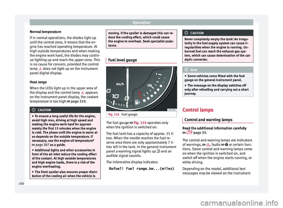
Fuel gauge. The fuel gauge
››
›
Fig. 114 operates only
when the ignition is switched on.
The fuel tank has a capacity of approx. 55 li-
tres. When the needle reaches the fuel re-
serve area there are only approximately 7 li-
tres left in the tank. In the general instrument
panel a warning signal lights up and an
audible signal sounds.
The informative display indicates:
Refuel! Fuel range…km...(miles) CAUTION
Never completely empty the tank! An irregu-
larity in the f
uel supply system can cause ir-
regularities when the engine is running. Un-
burned fuel can reach the exhaust gas sys-
tem, which can cause deterioration of the cat-
alytic converter. Note
● Some v ehic
les come fitted with the fuel
gauge on the general instrument panel.
● The message on the display switches off
only af
ter refuelling and carrying out a short
journey. Control lamps
C ontr
o
l and warning lamps Read the additional information carefully
› ›
›
page 33.
The control and warning lamps are indicators
of warnings, ››› , faults
››
›
or certain func-
tion s.
Some c
ontrol and warning lamps come
on when the ignition is switched on, and
switch off when the engine starts running, or
while driving.
Depending on the model, additional text
messages may be viewed on the instrument
100