towing Seat Toledo 2017 Owner's manual
[x] Cancel search | Manufacturer: SEAT, Model Year: 2017, Model line: Toledo, Model: Seat Toledo 2017Pages: 248, PDF Size: 5.86 MB
Page 5 of 248
Table of Contents
Table of Contents
The e s
senti
als . . . . . . . . . . . . . . . . . . . . . . . . 5
Exterior view . . . . . . . . . . . . . . . . . . . . . . . . . . . . 5
Exterior view . . . . . . . . . . . . . . . . . . . . . . . . . . . . 6
Interior view (left-hand drive) . . . . . . . . . . . . . . 7
Interior view (right-hand drive) . . . . . . . . . . . . . 8
How it works . . . . . . . . . . . . . . . . . . . . . . . . . . . . 9
Unlocking and locking . . . . . . . . . . . . . . . . . . . . 9
Before driving . . . . . . . . . . . . . . . . . . . . . . . . . . . 11
Airbags . . . . . . . . . . . . . . . . . . . . . . . . . . . . . . . . 14
Child seats . . . . . . . . . . . . . . . . . . . . . . . . . . . . . 16
Starting the vehicle . . . . . . . . . . . . . . . . . . . . . . 18
Lights and visibility . . . . . . . . . . . . . . . . . . . . . . 18
Easy Connect . . . . . . . . . . . . . . . . . . . . . . . . . . . 21
Driver information System . . . . . . . . . . . . . . . . . 23
Status display . . . . . . . . . . . . . . . . . . . . . . . . . . . 28
Cruise control . . . . . . . . . . . . . . . . . . . . . . . . . . . 32
Warning lamps . . . . . . . . . . . . . . . . . . . . . . . . . . 33
Gearbox lever . . . . . . . . . . . . . . . . . . . . . . . . . . . 35
Air conditioning . . . . . . . . . . . . . . . . . . . . . . . . . 37
Fluid Level control . . . . . . . . . . . . . . . . . . . . . . . 40
Emergencies . . . . . . . . . . . . . . . . . . . . . . . . . . . . 44
Fuses . . . . . . . . . . . . . . . . . . . . . . . . . . . . . . . . . . 44
Bulbs . . . . . . . . . . . . . . . . . . . . . . . . . . . . . . . . . . 45
Action in the event of a puncture . . . . . . . . . . . 45
Changing a wheel . . . . . . . . . . . . . . . . . . . . . . . 47
Snow chains . . . . . . . . . . . . . . . . . . . . . . . . . . . . 50
Emergency towing of the vehicle . . . . . . . . . . . 51
How to jump start . . . . . . . . . . . . . . . . . . . . . . . . 52
Changing the windscreen wiper blades . . . . . . 54
Safety . . . . . . . . . . . . . . . . . . . . . . . . . . . . . . . . 56
Safe driving . . . . . . . . . . . . . . . . . . . . . . . . . . . . 56
Safety first! . . . . . . . . . . . . . . . . . . . . . . . . . . . . . 56
Advice about driving . . . . . . . . . . . . . . . . . . . . . 56 Correct position of the vehicle occupants . . . . 57
Pedal area . . . . . . . . . . . . . . . . . . . . . . . . . . . . . . 61
Seat belts
. . . . . . . . . . . . . . . . . . . . . . . . . . . . . . 62
The whys and wherefores of seat belts . . . . . . . 62
How to properly adjust your seatbelt . . . . . . . . 65
Seat belt tensioners . . . . . . . . . . . . . . . . . . . . . . 66
Airbag system . . . . . . . . . . . . . . . . . . . . . . . . . . 67
Brief introduction . . . . . . . . . . . . . . . . . . . . . . . . 67
Airbag safety instructions . . . . . . . . . . . . . . . . . 70
Deactivating airbags . . . . . . . . . . . . . . . . . . . . . 72
Transporting children safely . . . . . . . . . . . . . . . 73
Safety for children . . . . . . . . . . . . . . . . . . . . . . . 73
Child seats . . . . . . . . . . . . . . . . . . . . . . . . . . . . . 75
Emergencies . . . . . . . . . . . . . . . . . . . . . . . . . . 76
Self-help . . . . . . . . . . . . . . . . . . . . . . . . . . . . . . . 76
Emergency equipment . . . . . . . . . . . . . . . . . . . . 76
Changing a wheel . . . . . . . . . . . . . . . . . . . . . . . 76
Tyre repairs . . . . . . . . . . . . . . . . . . . . . . . . . . . . . 77
Towing the vehicle . . . . . . . . . . . . . . . . . . . . . . . 79
Fuses and bulbs . . . . . . . . . . . . . . . . . . . . . . . . . 81
Fuses . . . . . . . . . . . . . . . . . . . . . . . . . . . . . . . . . . 81
Changing bulbs . . . . . . . . . . . . . . . . . . . . . . . . . 84
Changing the fog light bulbs . . . . . . . . . . . . . . . 88
Changing the rear lights (on the side panel) . . 88
Changing tail lights (on the rear lid) . . . . . . . . . 90
Changing the bulb on the number plate . . . . . . 92
Side turn signals . . . . . . . . . . . . . . . . . . . . . . . . 92
Operation . . . . . . . . . . . . . . . . . . . . . . . . . . . . . 95
Controls and displays . . . . . . . . . . . . . . . . . . . . 95
General instrument panel . . . . . . . . . . . . . . . . . 94
Instruments and warning lamps . . . . . . . . . . . . 96
Instruments . . . . . . . . . . . . . . . . . . . . . . . . . . . . 96
Control lamps . . . . . . . . . . . . . . . . . . . . . . . . . . . 100
Introduction to the Easy Connect system* . . . . 101
System settings (CAR)* . . . . . . . . . . . . . . . . . . . 101 Communications and multimedia
. . . . . . . . . . . 103
Steering wheel controls* . . . . . . . . . . . . . . . . . . 103
Multimedia . . . . . . . . . . . . . . . . . . . . . . . . . . . . . 108
Opening and closing . . . . . . . . . . . . . . . . . . . . . 108
Remote control . . . . . . . . . . . . . . . . . . . . . . . . . . 108
Keys . . . . . . . . . . . . . . . . . . . . . . . . . . . . . . . . . . . 109
Central locking system . . . . . . . . . . . . . . . . . . . . 111
Anti-theft alarm* . . . . . . . . . . . . . . . . . . . . . . . . 116
Rear lid . . . . . . . . . . . . . . . . . . . . . . . . . . . . . . . . 118
Controls for the windows . . . . . . . . . . . . . . . . . . 119
Lights and visibility . . . . . . . . . . . . . . . . . . . . . . 120
Lights . . . . . . . . . . . . . . . . . . . . . . . . . . . . . . . . . 120
Interior lights . . . . . . . . . . . . . . . . . . . . . . . . . . . 126
Visibility . . . . . . . . . . . . . . . . . . . . . . . . . . . . . . . 127
Windscreen wipers and windscreen wash-
ers . . . . . . . . . . . . . . . . . . . . . . . . . . . . . . . . . . . . 128
Mirr
ors . . . . . . . . . . . . . . . . . . . . . . . . . . . . . . . . . 130
Seats and head restraints . . . . . . . . . . . . . . . . . 131
Adjusting seats and head restraints . . . . . . . . . 131
Seat functions . . . . . . . . . . . . . . . . . . . . . . . . . . 132
Transport and practical equipment . . . . . . . . . 135
Practical equipment . . . . . . . . . . . . . . . . . . . . . . 135
Storing objects . . . . . . . . . . . . . . . . . . . . . . . . . . 140
Luggage compartment . . . . . . . . . . . . . . . . . . . . 141
Roof rack* . . . . . . . . . . . . . . . . . . . . . . . . . . . . . . 144
Air conditioning . . . . . . . . . . . . . . . . . . . . . . . . . 146
Heating and air conditioning . . . . . . . . . . . . . . . 146
Heating and fresh air . . . . . . . . . . . . . . . . . . . . . 148
Air conditioning (manual)* . . . . . . . . . . . . . . . . 148
Climatronic* (automatic air conditioning) . . . . 150
Driving . . . . . . . . . . . . . . . . . . . . . . . . . . . . . . . . 152
Starting and stopping the engine . . . . . . . . . . . 152
Brakes and brake servo systems . . . . . . . . . . . . 156
Braking and stability systems . . . . . . . . . . . . . . 158
Manual gearbox . . . . . . . . . . . . . . . . . . . . . . . . . 160
Automatic gearbox . . . . . . . . . . . . . . . . . . . . . . . 160
Run-in and economical driving . . . . . . . . . . . . . 165
3
Page 6 of 248
Table of Contents
Engine management and emission control sys-
t em
. . . . . . . . . . . . . . . . . . . . . . . . . . . . . . . . . . . 167
Driv
ing tips . . . . . . . . . . . . . . . . . . . . . . . . . . . . . 169
Driver assistance systems . . . . . . . . . . . . . . . . . 170
Parking aid . . . . . . . . . . . . . . . . . . . . . . . . . . . . . 170
Rear Assist “Rear View Camera”* . . . . . . . . . . . 175
Cruise speed (Cruise Control)* . . . . . . . . . . . . . 178
Emergency brake assist system (Front As-
sis
t)* . . . . . . . . . . . . . . . . . . . . . . . . . . . . . . . . . . 179
Start-Stop System* . . . . . . . . . . . . . . . . . . . . . . . 183
Fatigue detection (break recommendation)* . . 185
Towing bracket device . . . . . . . . . . . . . . . . . . . . 186
Driving with a trailer . . . . . . . . . . . . . . . . . . . . . . 186
Towing bracket device . . . . . . . . . . . . . . . . . . . . 188
Advice . . . . . . . . . . . . . . . . . . . . . . . . . . . . . . . . 194
Care and maintenance . . . . . . . . . . . . . . . . . . . . 194
Accessories and modifications to the vehi-
cle
. . . . . . . . . . . . . . . . . . . . . . . . . . . . . . . . . . . . 194
Care and cleaning . . . . . . . . . . . . . . . . . . . . . . . 195
Checking and refilling levels . . . . . . . . . . . . . . . 201
Fuel . . . . . . . . . . . . . . . . . . . . . . . . . . . . . . . . . . . 201
Engine compartment . . . . . . . . . . . . . . . . . . . . . 204
Engine oil . . . . . . . . . . . . . . . . . . . . . . . . . . . . . . 207
Coolant . . . . . . . . . . . . . . . . . . . . . . . . . . . . . . . . 210
Brake fluid . . . . . . . . . . . . . . . . . . . . . . . . . . . . . 211
Window washer system . . . . . . . . . . . . . . . . . . . 212
Battery . . . . . . . . . . . . . . . . . . . . . . . . . . . . . . . . . 213
Wheels and tyres . . . . . . . . . . . . . . . . . . . . . . . . 217
Tyres . . . . . . . . . . . . . . . . . . . . . . . . . . . . . . . . . . 217
Spare wheel . . . . . . . . . . . . . . . . . . . . . . . . . . . . 220
Tyre monitoring systems . . . . . . . . . . . . . . . . . . 221
Winter service . . . . . . . . . . . . . . . . . . . . . . . . . . . 222
Technical data . . . . . . . . . . . . . . . . . . . . . . . . 223
Technical specifications . . . . . . . . . . . . . . . . . . 223
Important information . . . . . . . . . . . . . . . . . . . . 223
Information on fuel consumption . . . . . . . . . . . 224 Driving with a trailer . . . . . . . . . . . . . . . . . . . . . . 225
Wheels . . . . . . . . . . . . . . . . . . . . . . . . . . . . . . . . 226
Engine data . . . . . . . . . . . . . . . . . . . . . . . . . . . . . 227
Dimensions . . . . . . . . . . . . . . . . . . . . . . . . . . . . . 233
Index . . . . . . . . . . . . . . . . . . . . . . . . . . . . . . . . . 235
4
Page 31 of 248
The essentials
Gear-change indicator Fig. 38
Instrument panel: gear-change indica-
t or (m
anual
gearbox). A gear change will be recommended if the
g
e
ar
you are in is not the most economical
choice. If no gear-change is recommended, it
means that you are already in the most eco-
nomical gear.
Vehicles with a manual gearbox
The following display symbols ›››
Fig. 38
mean:
● Chan ge to a higher gear: the suggested
g
ear appears to the right of the current gear
when a higher gear is recommended .
● Change to a lower gear: the suggested
g
ear appears to the left of the current gear
when a lower gear is recommended .
The gear recommendation may occasionally
skip a gear (2nd 4th). Vehicles with an automatic gearbox*
The dis
p
lay is only visible in tiptronic mode
››› page 163.
The following display symbols mean:
● Shiftin g up a gear
●
Shifting down a gear CAUTION
The gear-change indicator is intended to help
sav e f
uel, but it is not intended to recom-
mend the right gear for all driving situations.
In certain situations, only the driver can
choose the correct gear (for instance when
overtaking, driving up a steep gradient or
towing a trailer). Note
The display disappears from the instrument
panel when
you press the clutch pedal. Outside temperature display
Outside temperature
When the outs
ide t
emper
ature is below +4°C
(+39°F), the “ice crystal” symbol (warning of
risk of freezing) is also displayed. At first, this
symbol flashes and then it remains lit until
the outside temperature rises above +6°C
(+43°F) ››› in Indications on the display on
p ag
e 98
. When the vehicle is at a standstill or when
travel
ling at very low speeds, the tempera-
ture displayed may be higher than the true
outside temperature as a result of the heat
produced by the engine.
The temperatures measured range from
-40°C to +50°C (-40°F to +122°F).
Engine oil temperature display Vehicles without multifunction steering
wheel
● Press the rocker switch ›
››
Fig. 35 2 until
the m ain menu ap
pe
ars. Enter into Driving
data . With the button 2 move to the oil
t emper
at
ure gauge.
Vehicles with multifunction steering wheel
● Enter the submenu Driving data and
turn the thumbwheel
until the oil tempera-
ture display appears.
The engine reaches its operating temperature
when in normal driving conditions, the oil
temperature is between 80°C (180°F) and
120°C (250°F) . If the engine is required to
work hard and the outside temperature is
high, the engine oil temperature can in-
crease. This does not present any problem as
long as the warning lamps ›››
table on
page 34 or ››› table on page 34 do not
appear on the display. 29
Page 47 of 248
The essentials
To replace a fuse
● Remove the fuse.
● Replace the blown fuse by one with an
iden tic
a
l amperage rating (same colour and
markings) and identical size.
● Replace the cover again or close the fuse
box lid.
B
ulbs
Bul
bs (12 V) Full-LED headlights are designed to last the
lif
etime of
the c
ar and cannot be replaced. If
the headlight becomes damaged, go to a
specialised workshop.
Below, the light source used for all functions
is broken down.
Halogen headlights.Type
Daytime running light/side
lightP21W SLL
Dipped beam headlightsH7 LL
Main beam headlightsH7 LL
Turn signalPY21W
Full-LED main headlightsType
No bulbs may be replaced. All functions are with LEDs
Front fog lightType
Fog/cornering lights*H8
Rear bulb lightType
Brake light/tail lightP21/5W
Side lightsP21/5W (side panel)
R5W (rear lid)
Turn signalPY21W
Retro fog lightP21W
Reverse lightsP21W
LED rear lightsType
Turn signalPY21W
Retro fog lightP21W
Reverse lightsP21W
The remaining functions work with LEDs
›››
page 84 Action in the event of a punc-
t
ur
e
Wh
at to do first ●
Park the vehicle on a horizontal surface
and in a saf e p
lace as far away from traffic as
possible.
● Apply the handbrake.
● Switch on the hazard warning lights.
● Manual gearbox: select the 1s
t gear.
● Automatic gearbox: Move the sel
ector lever
to position P.
● If you are towing a trailer, unhitch it from
your v
ehicle.
● Have the vehicle tool kit* ›››
page 76
and the spare wheel ›››
page 220 ready.
● Observe the applicable legislation for each
countr
y (reflective vest, warning triangles,
etc.).
● All occupants should leave the vehicle and
wait in a s
afe place (for instance behind the
roadside crash barrier). WARNING
● Alw a
ys observe the above steps and pro-
tect yourself and other road users.
● If you change the wheel on a slope, block
the wheel on the oppo
site side of the car with
a stone or similar to prevent the vehicle from
moving. 45
Page 49 of 248
The essentials
Changing a wheel V ehic
l
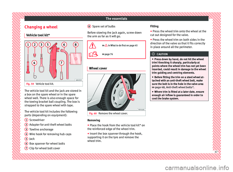
e tool kit* Fig. 59
Vehicle tool kit. The vehicle tool kit and the jack are stored in
a bo
x
on the s
pare wheel or in the spare
wheel well. There is also enough space for
the towing bracket ball coupling. The box is
strapped to the spare wheel with tape.
The vehicle tool kit includes the following
parts (depending on equipment):
Screwdriver
Adapter for anti-theft wheel bolts
Towline anchorage
Wire hook for removing hub caps
Jack
Box spanner for wheel bolts
Clip for wheel bolt cover
1 2
3
4
5
6
7 Spare set of bulbs
B ef
or
e stowing the jack again, screw down
the arm as far as it will go.
››› in What to do first on page 45
››› page 76 Wheel cover
Fig. 60
Remove the wheel cover. Removing
● Place the hook from the vehicle tool kit* on
the r einf
or
ced edge of the wheel trim.
● Insert the box spanner through the hook,
suppor
ting it on the tyre and remove the
wheel trim. 8 Fitting
●
Press the wheel trim onto the wheel at the
c ut
out
designed for the valve.
● Press the wheel trim on both sides in the
direction of the
valve so that it fits correctly
in place around all the perimeter. CAUTION
● Pre s
s down by hand, do not hit the wheel
trim! Knocking it sharply, particularly at
points where the wheel trim has not yet been
inserted, could result in damage to the wheel
trim guiding and centring elements.
● Before fitting the trim on a steel wheel at-
tached w
ith an anti-theft wheel bolt, make
sure the bolt is in the hole in the valve area
››› page 48, Anti-theft wheel bolts*.
● Where trim is fitted at a later date, ensure
enough air inflow is
guaranteed in order to
cool the brake system. 47
Page 53 of 248
The essentials
In winter road conditions, snow chains not
on ly
help t
o improve grip but also improve
the braking capacity.
For technical reasons snow chains may only
be used on tyres with the following wheel
rim/tyre combinations.
Rim sizeRim offsetTyre size
5J x 14 a)35 mm175/70
6J x 15b)38 mm185/60
6J x 15b)38 mm195/55
a)
Only use snow chains with fine-pitch links and lock no greater
than 9 mm.
b) Only use snow chains with fine-pitch links and lock no greater
than 13 mm.
Remove the wheel trims before fitting snow
chains. CAUTION
Chains must be removed when roads are free
of s no
w. Otherwise they will impair handling,
damage the tyres and wear out very quickly. Emergency towing of the vehi-
c
l
e
T
owing Fig. 66
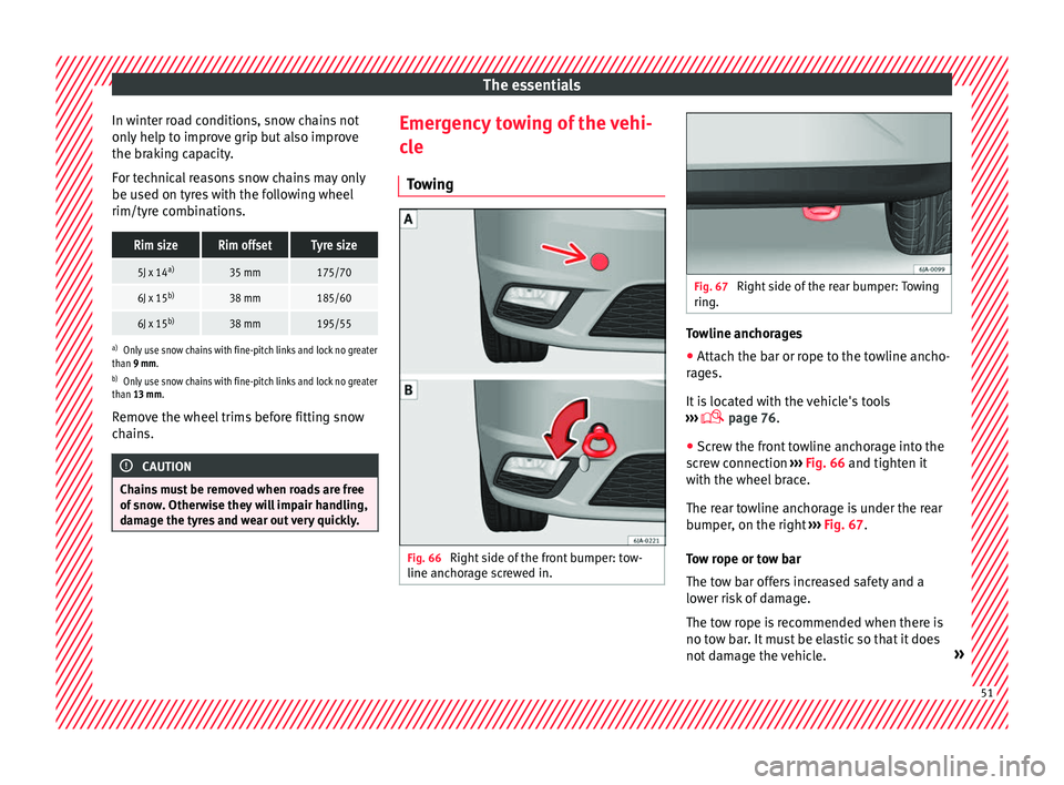
Right side of the front bumper: tow-
line anc hor
ag
e screwed in. Fig. 67
Right side of the rear bumper: Towing
ring. Towline anchorages
● Attach the bar or rope to the towline ancho-
r ag
e
s.
It is located with the vehicle's tools
››› page 76.
● Screw the front towline anchorage into the
scr
ew connection ››› Fig. 66 and tighten it
with the wheel brace.
The rear towline anchorage is under the rear
bumper, on the right ››› Fig. 67.
Tow rope or tow bar
The tow bar offers increased safety and a
lower risk of damage.
The tow rope is recommended when there is
no tow bar. It must be elastic so that it does
not damage the vehicle. » 51
Page 54 of 248
The essentials
Notes for the driver of the towing vehicle
● The tow rope must be taut before you drive
off .
● Rel
ease the clutch very carefully when start-
ing the v
ehicle (manual gearbox), or acceler-
ate gently (automatic gearbox).
Driving style
Towing requires some experience, especially
when using a tow rope. Both drivers should
realise how difficult it is to tow a vehicle. In-
experienced drivers should not attempt to
tow.
Do not pull too hard with the towing vehicle
and take care to avoid jerking the tow rope.
When towing on an unpaved road, there is al-
ways a risk of overloading and damaging the
anchorage points.
The towline anchorages are located under
the floor panel in the luggage compartment.
Switch on the ignition so that the turn sig-
nals, windscreen wipers and windscreen
washer can work. Ensure that the steering
wheel is unlocked and moves freely.
Place the gear lever in neutral on vehicles
with a manual gearbox. With an automatic
gearbox, place the lever in N.
To brake, press the brake pedal firmly. The
brake servo does not work when the engine
is switched off. The power steering only works when the igni-
tion is sw
itched on and the vehicle is moving,
provided that the battery is sufficiently charg-
ed. Otherwise, it will need more force.
Ensure that the tow rope remains taut at all
times.
››› page 79 Tow-starting
If the engine will not start, first try starting it
u
s
in
g the battery of another vehicle
››› page 52. You should only attempt to tow-
start a vehicle if charging the battery does
not work. This is done by leveraging wheel
movement.
When tow-starting a vehicle with a petrol en-
gine, do not tow it more than a short dis-
tance, otherwise unburned fuel can enter the
catalytic converter.
● Engage 2nd or 3rd gear before moving off.
● Press the clutch and hold the pedal down.
● Switch the ignition on.
● Once both vehicles are moving, release the
clutc
h.
● As soon as the engine has started, press
the clutc
h and move the gear lever to neutral. How to jump start
Jump lea
ds The jump lead must have a sufficient wire
cr
o
ss section.
If the engine fails to start because of a dis-
charged battery, the battery can be connec-
ted to the battery of another vehicle to start
the engine.
Both batteries need to have nominal voltage
of 12 V. The capacity (Ah) of the back-up bat-
tery should not be notably less than the
drained battery.
Jump leads must comply with standard DIN
72553 (see cable manufacturer's instruc-
tions). The wire cross section must be at least
25 mm 2
for petrol engines and at least
35 mm 2
for diesel engines.
Jump leads
Positive cable – usually red
Negative cable – usually black WARNING
● A flat b
attery can also freeze at tempera-
tures slightly below 0°C (+32°F). Do not at-
tempt to start the vehicle with a frozen bat-
tery. Risk of explosion! 52
Page 81 of 248
Self-help
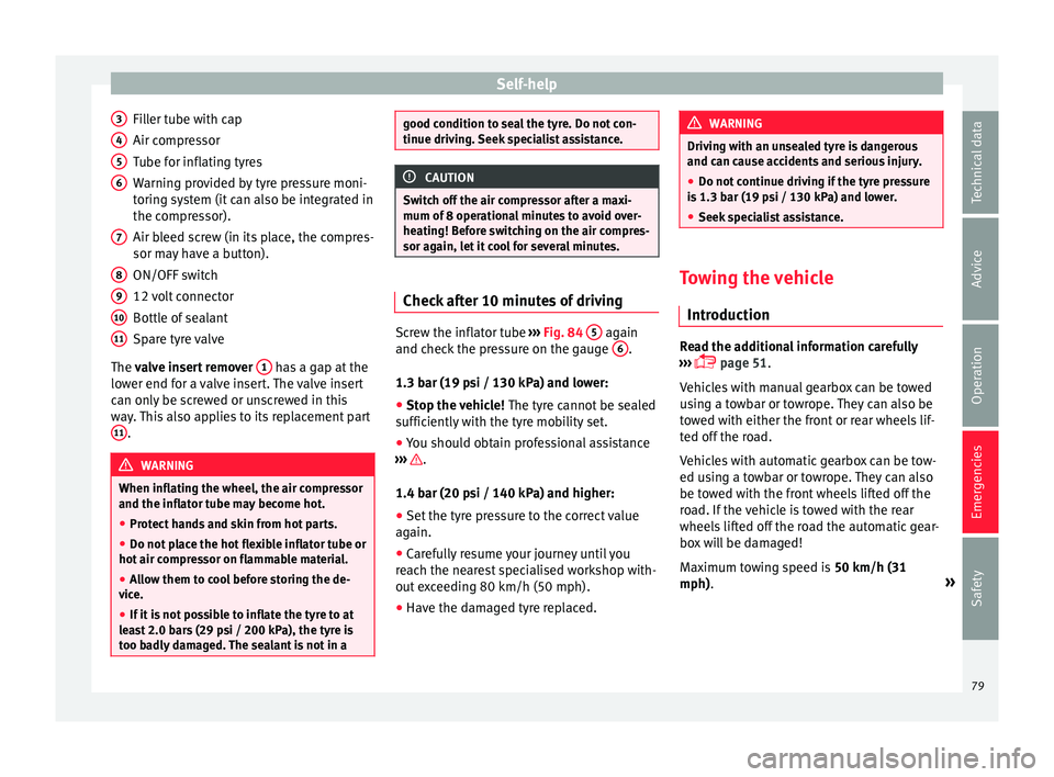
Filler tube with cap
Air c ompr
e
ssor
Tube for inflating tyres
Warning provided by tyre pressure moni-
toring system (it can also be integrated in
the compressor).
Air bleed screw (in its place, the compres-
sor may have a button).
ON/OFF switch
12 volt connector
Bottle of sealant
Spare tyre valve
The valve insert remover 1 has a gap at the
lo w
er end f
or a valve insert. The valve insert
can only be screwed or unscrewed in this
way. This also applies to its replacement part 11 .
WARNING
When inflating the wheel, the air compressor
and the inflat or t
ube may become hot.
● Protect hands and skin from hot parts.
● Do not place the hot flexible inflator tube or
hot air compr
essor on flammable material.
● Allow them to cool before storing the de-
vice.
● If
it is not possible to inflate the tyre to at
lea
st 2.0 bars (29 psi / 200 kPa), the tyre is
too badly damaged. The sealant is not in a 3
4
5
6
7
8
9
10
11 good condition to seal the tyre. Do not con-
tinue drivin
g.
Seek specialist assistance. CAUTION
Switch off the air compressor after a maxi-
mum of 8 operation
al minutes to avoid over-
heating! Before switching on the air compres-
sor again, let it cool for several minutes. Check after 10 minutes of driving
Screw the inflator tube
››
›
Fig. 84 5 again
and c hec
k
the pressure on the gauge 6 .
1.3 b ar (19 p
s
i / 130 kPa) and lower:
● Stop the vehicle! The tyre c
annot be sealed
sufficiently with the tyre mobility set.
● You should obtain professional assistance
›››
.
1.4 b ar (20 p
s
i / 140 kPa) and higher:
● Set the tyre pressure to the correct value
again.
● Car
efully resume your journey until you
reac
h the nearest specialised workshop with-
out exceeding 80 km/h (50 mph).
● Have the damaged tyre replaced. WARNING
Driving with an unsealed tyre is dangerous
and can c au
se accidents and serious injury.
● Do not continue driving if the tyre pressure
is 1.3
bar (19 psi / 130 kPa) and lower.
● Seek specialist assistance. Towing the vehicle
Introduction Read the additional information carefully
› ›
›
page 51.
Vehicles with manual gearbox can be towed
using a towbar or towrope. They can also be
towed with either the front or rear wheels lif-
ted off the road.
Vehicles with automatic gearbox can be tow-
ed using a towbar or towrope. They can also
be towed with the front wheels lifted off the
road. If the vehicle is towed with the rear
wheels lifted off the road the automatic gear-
box will be damaged!
Maximum towing speed is 50 km/h (31
mph). »
79
Technical data
Advice
Operation
Emergencies
Safety
Page 82 of 248
Emergencies
CAUTION
● Do not t o
w-start the engine. Risk of engine
damage! In vehicles with a catalytic convert-
er, fuel that has not been burned could reach
the catalytic converter and catch fire in it.
This could damage and destroy the catalytic
converter. You may use the battery from an-
other vehicle to help you start your engine
››› page 53.
● If, due to a fault, there is no oil in the gear-
box, the car m
ay only be towed with the driv-
en wheels lifted clear of the road and trans-
ported on a special vehicle transporter or
trailer.
● If normal towing is not possible or if the ve-
hicle i
s to be towed for further than 50 km,
the vehicle must be transported on a special
vehicle transporter or trailer.
● The towrope should be slightly elastic to
reduce the lo
ad on both vehicles during tow-
ing. It is advisable to use a towrope made of
synthetic fibre or similar material only.
● Do not pull too hard with the towing vehicle
and alwa
ys take care to avoid jerking the tow-
rope. When towing on a loose surface there is
always a risk of overloading and damaging
the anchorage points.
● Attach the towrope or towbar only to the
towline anc
horages or to the removable tow-
ing bracket ››› page 186, or ››› page 80. Note
● We r ec
ommend you use the towrope or tow-
bar available in the SEAT Original Accessories
programme from authorised SEAT dealers.
● Towing a vehicle requires a certain degree
of practic
al skill. Both drivers should be fa-
miliar with the technique required for towing.
Inexperienced drivers should not attempt to
tow away another vehicle or to have their ve-
hicle towed.
● Note the legal regulations concerning tow-
ing, par
ticularly those regarding the signal-
ling of the towed and towing vehicle.
● The towrope must not be twisted, as under
cert
ain circumstances this could unscrew the
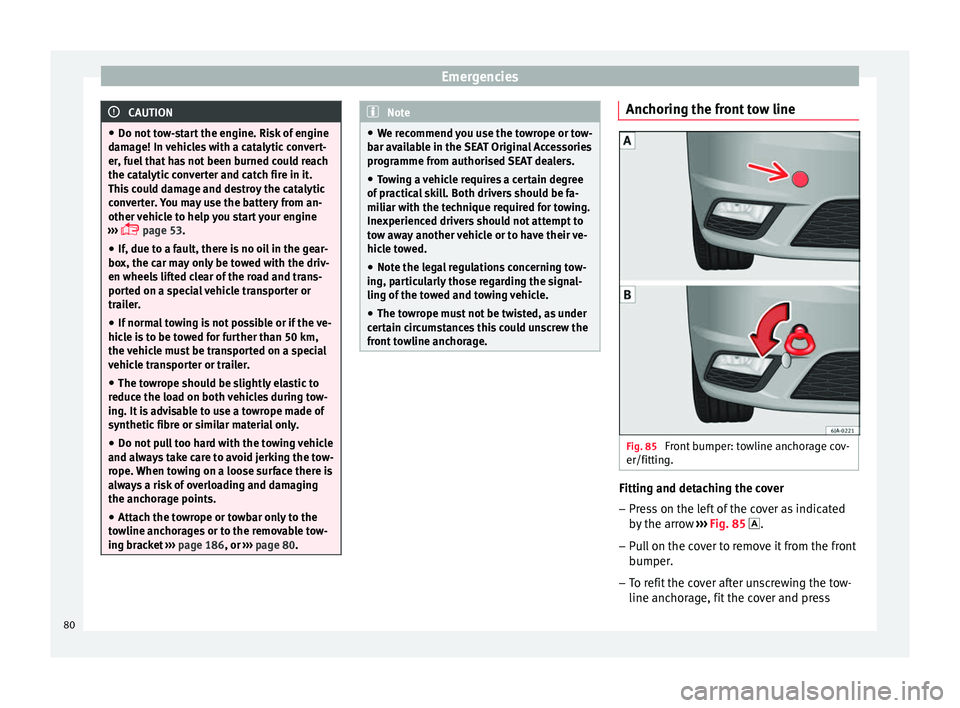
front towline anchorage. Anchoring the front tow line
Fig. 85
Front bumper: towline anchorage cov-
er/fittin g. Fitting and detaching the cover
– Press on the left of the cover as indicated
by
the arr
ow ››› Fig. 85 .
– Pull on the cover to remove it from the front
bumper.
– T
o refit the cover after unscrewing the tow-
line anchorag
e, fit the cover and press
80
Page 83 of 248
Fuses and bulbs
down on its right-hand side. The cover
mu s
t
be securely engaged.
Fitting and detaching the towline anchorage
– Screw in the towline anchorage anti-clock-
wise b
y hand as far as it will go ››› Fig. 85
.
To tighten the towline anchorage, we recom-
mend using the box spanner, the towing eye
from another vehicle or a similar object that
can be inserted through the anchorage.
– Unscrew the towline anchorage by turning
it cloc
kwise. CAUTION
The towline anchorage must be screwed in as
far a s
it will go. Otherwise there is a risk of
the screw connection shearing off during
towing or tow-starting! Fuses and bulbs
F u
se
s
Introduction Due to the constant updating of vehicles,
fu
se a
ssignments based on equipment and
the use of the same fuse for various electrical
components, it is not possible to provide an
up-to-date summary of the fuse positions for
the electrical components at the time this
manual was printed. For detailed information
about the fuse positions, please consult a
technical service.
In general, a fuse can be assigned to various
electrical components. Likewise, an electrical
component can be protected by several
fuses.
Only replace fuses when the cause of the
problem has been solved. If a newly inserted
fuse blows after a short time, you must have
the electrical system checked by a special-
ised workshop as soon as possible.
Additional information and warnings:
● Working in the engine compartment
›› ›
page 204. WARNING
The high voltages in the electrical system can
give seriou s
electrical shocks, causing burns
and even death!
● Never touch the electrical wiring of the igni-
tion syst
em.
● Take care not to cause short circuits in the
electrica
l system. WARNING
Using unsuitable fuses, repairing fuses or
bridging a c urr
ent circuit without fuses can
cause a fire and serious injury.
● Never use a fuse with a higher value. Only
repl
ace fuses with a fuse of the same amper-
age (same colour and markings) and size.
● Never repair a fuse.
● Never replace a fuse by a metal strip, staple
or simil
ar. CAUTION
● To pr ev
ent damage to the vehicle's electric
system, before replacing a fuse always turn
off the ignition, the lights and all electrical
elements and remove the key from the igni-
tion.
● If you replace a fuse with higher-rating
fuse,
you could cause damage to another part
of the electrical system. » 81
Technical data
Advice
Operation
Emergencies
Safety