mirror SKODA 120 LSE 1980 Workshop Manual
[x] Cancel search | Manufacturer: SKODA, Model Year: 1980, Model line: 120 LSE, Model: SKODA 120 LSE 1980Pages: 238, PDF Size: 47.09 MB
Page 54 of 238

6.
Complete the pump
ossembly by fitting
the
Stouffer lubricotor filled with
the recommended
greose.
2.15 ROCKER SHAFT AND ROCKERS
Assembly (on
Skodo 105 engine)
1. Instoll the lock ring, ploin
wosher, ond
spring wosher on the ro6ker shoft
with both
ends plugged.
Smeor the shoft with oil, fit the
rocker (with
its orm with the thrust foce de-
flected toword the next ossembled ports),
the
shim, the rocker support, ond the other
orm
def lected toword the support, i. e. the complete
rocker unit of cylinder
No. 1.
2. Then slip the spring,
the rocker, the sup-
port, the shim,
ond the next rocker, i.e.
the
complete rocker unit of cylinder
No.2, on the
shoft.
3. Threod on the spring ond, using the mirror
orrongement of the ossembled
rocker units,
instoll the rocker
units of the remoining
two
cylinders. Use o lock ring supplemented
with
o ploin
ond o spring wosher
to lock the os-
sembled ports
in position.
The rocker support of the cylinder No.4 must
be provided
with on oil hole
to provide
for the
supply of oil to the rocker shoft.
4. Compress
the springs
by holding down the
rocker orms ond lubricote
oll loterol contoct
surfoces with oil.
Assembly (on Skodo 120 L
ond 120 LS engines)
The rocker shoft is provided
with two od-
ditionol rocker supports fitted from
the outside
of the rocker units (the
shoft is longer), re-
plocing woshers obutting
on the lock rings.
For
the rest, the ossembly is identiccl
with the pro-
cedure described in porogrophs
1 to 4 obove.
NJote: Rocker orms
on the Skodo 120 LS en-
gine ore shorter (18.5
mm) thon those on the
Skodo -120
L ond Skodo 105 engines,
in order
to obtoin o higher rotio.
Disossembly
Remove the lock ring from the shoft
end ond
strike off the
entire volve nocker geor
from
the
shoft.
2.16 CYLINDER HEAD, VALVES
AND
SPRINGS
The cylinder heod is o costing of speciol grey
cost iron. The volve seots ond guides
ore cost
ond mochined directlv in tlre heod. The volves ore of different
diometers, the intoke volves
being lorger. Outer (exhoust)
ports
ore single,
oll remoinlng ore doubled, i.e. bifurcoted
ond
bronching to two volves in odioining
cylinders.
The centre exhoust port
bronches to the cyl.
inders No.2 ond 3, the neighbouring
intoke port
to the cylinders No. 1 ond 2, ond No. 3 ond 4.
The cylinder heod con be hondled
in the cor os
o unit. Of the individuol
iobs, only
the reploce-
ment of volve springs,
cotters, ond cylinder
heod bolts con be corried out with the engine
in. position in the cor. For oll the remoining
iobs, the
cylinder heod hos to be removed
from
the cor.
To remove
the volve springs,
screw out
the
sporking plugs ond, using o tommy
bor with
o curved end (steel
bor of obout 5 mm dio-
meter), broce
the volve to prevent
it from
sliding down into the combustion
chomber.
To Remove
Cylinder Heod from Engine
1. Let
the engine cool down before removing
the cylinder heod to preclude
worping of its
beoring surfoce.
2. Droin
the coolont into o cleon vessel (see
Chopter 15.13), detoch oll ports
connecting the
cylinder heod to the vehicle,
ond remove
oll
ports which ore likely
to obstruct the removol.
3. Remove the oir cleoner,
lift owoy
the
cylinder heod cover, ond remove
the nuts ond
bolts holding down
the cylinder heod (on
en-
gines of Skodo 120 L
ond 120 LS cors, two
bolts olso hold down
the end rocker
shoft sup-
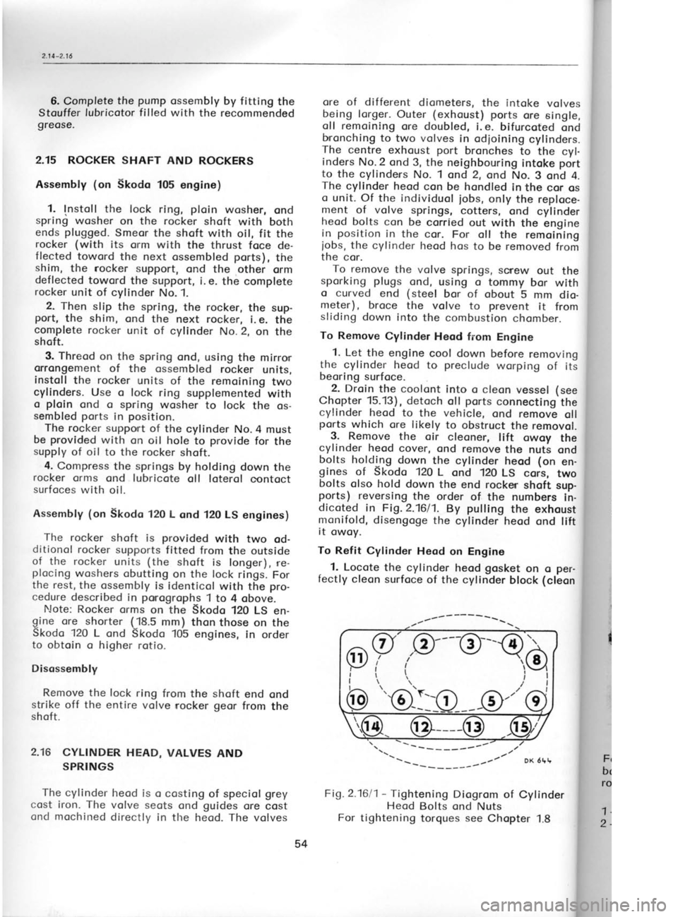
ports) reversing the order of the numbers
in-
dicoted in Fig. 2.1611.
By pulling
the exhoust
monifold, disengoge the
cylinder heod ond lift
it owoy.
To Refit Cylinder
Heod on Engine
. 1.
Locote the cylinder heod gosket
on o per-
fectly cleon surfoce of the cylinder
block (cleon
Fi1.2.1611- Tightening Diogrom of Cylinder
Heod Bolts ond Nuts
For tightening torques see Chopter
1.8 the
cylinc
the oilwo,
structed c
Releose
once odjur
heod. lf nr
the rocker
2. Swin<
down the
porogroph
opply the
liminory o
the sequ€
(Fig. 2.16/
shoft suppr
3. Adjus
ter 2.13,
re
cleoner, rer
tighten oll
Cylinder Hr
Disossem
heod on o r
o support i
it does
not
o iob from
t
An exomple
1. Remove
the cosing
control, end
geor ofter
supports.
Fig.2Je
For holding
c
bolt M 8 scrt
rocker-shoft st
1 -
MP 1-113
v,
2 -
MP 1-114
v
Itl
I
I
/\.
-
( 3 r--{ 4)
\-/
\II
l
/
,/
t___v'
?,3
"'@-:lO
54
Page 175 of 238

I
I
I
s
I
I
I
t
(
(
t
l
,
t
T c
R
L D
v Ir
1' 2
3
orotely
(
screen the other one) . With lef t
directionol heodlomps,
the borderline deviotes
towords the other
side.
lf the heodlomps ore neorer to the woll thon
the soid
5 metres, decreose the meosure indi-
coting the
deviotion of the light ond
dorkness
bordeiline from the
height of the heodlomps
obove the ground in the
direct proportion to
the
decreose of
tfre distonce, for
exomple when
plocing the cor 2.5 metres
from the woll, de-
creose the deviotion bY holf.
Light proiections "A"
ond "B"
correspond to
the spocing of heodlomPs on
the cor ond they
hove the following dimensions:
Heodlomps, dio. 160
mm 1,030
mm
Duol heodlomps, dio.
130 mm 1,114
mm
Auxiliory heodlomps, dio.
130 mm 790 mm
When odjusting the heodlomps, the cor must
be empty ond the
tyres must be correctly in-
floted. Hologen heodlomps should
not be left
switched on for too long o period os they build
up heot if not cooled by heod-on
oir blost when
driving. For lhe odiustment of
heodlomPs ore intended
screws in their fromes. The screws
ore occess'
ible ofter the removol of the side ports
of the
grille. Remove the copscrews of the corners
ond push
the grille
oside.
Heodlomp Assembly
o) The fundomentol fostening
Port of
circulor
heodlomps is the
so-colled support plote
(rec-
tongulor plote)
ottoched to the bodywork by
copscrews with lock woshers. The
heodlomp
housing is bolted to this suPPort plote by bolts
with nuts ond lock woshers. One of the bolts holds
down olso the
lug of the eorthing coble-
The inner frome,
forming the
odiusting element
of the heodlomp insert, is ottoched
to the
hous'
ing by two speciol odiusting screws
ond two
tension springs. The heodlomp insert
is ot'
toched to
the bezel by
three copscrews.
There is one left-hond ond
one right-hond
support plote.
Both should
be mounted with the
oriow ond the word "TOP"
upwords. With
the
exception of the ouxiliory heodlomps, the
heod'
lomp inserts ore different for
the left-hond ond
the right-hond troffic. The leods
enter the hous-
ing through o
rubber grommet.
When r-eplocing the insert, remove
the bezel
copscrews. After
hoving fitted o new insert, it
is necessory to reodiust the
heodlomps.
Front Direction Indicotors
The right-hond ond
left-hond direction indi-
cotors ore undisossembloble units
(the
lomp
fostening sockets (locks) ore
mounted in the
direction towords the cor longitudinol centre
line). They ore fostened to their brockets in the
bumper with o nut ond o ploin ond
o lock
wosher.
Toil Lomp Cluster
The lomp cluster is on undisossembloble unit
fostened to
the bodywork by
nuts with ploin
woshers ond the
respective bolts.
Scrope off
the enomel ot the
top bolt used for holding
down the eorthing coble.
For the sequence
of the individuol lomps ond
their bulbs see Fig. 13.111 ond the respective
porogroph on bulbs.
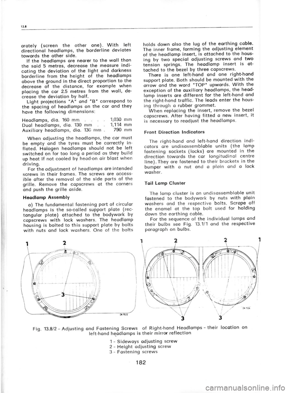
Fig. 13.812 -
Adiusting ond
Fastening Screws of Right-hond Heodlomps -
their locotion
on
left-hond he-odlomps is their
mirror ref lection
1 -
Sidewoys odiusting screw
2 -
Height odiusting screw
3 -
Fostening screws
182