fuel pressure SKODA CITIGO 2013 1.G Owner's Manual
[x] Cancel search | Manufacturer: SKODA, Model Year: 2013, Model line: CITIGO, Model: SKODA CITIGO 2013 1.GPages: 176, PDF Size: 10.54 MB
Page 21 of 176
CAUTIONThe red oil pressure light is not an oil level indicator! One should therefore
check the oil level at regular intervals, preferably after every refuelling stop.
Coolant
First read and observe the introductory information and safety warn-ings
on page 16.
The warning light comes on for a few seconds when the ignition is switched
on.
If the warning light
lights up or flashes, either the coolant temperature is too
high or the coolant level is too low.
An audible signal sounds as a warning tone.
Stop the vehicle, switch off the engine, check the level of the coolant » page 132,
and refill the coolant if necessary » page 133.
Do not continue your journey if for some reason it is not possible to top up the
coolant under the prevailing conditions. This can cause serious engine damage.
Therefore, switch the engine off and seek help from a specialist garage.
If the coolant is within the specified range, the increased temperature may be
caused by an operating problem at the radiator fan. Check the fuse for the radia-
tor fan, replace if necessary » page 156, Fuses in the engine compartment .
Do not continue driving if the warning light
does not go off even though the
coolant level is correct and the fuse for the fan is in working order!
Seek help from a specialist garage.
WARNINGIf you have to stop for technical reasons, then park the vehicle at a safe dis- tance from the traffic, switch off the engine and activate the hazard warning
lights » page 36 .
Power steering
First read and observe the introductory information and safety warn-
ings
on page 16.
The warning light comes on for a few seconds when the ignition is switched
on.
If the warning light after switching on the ignition or when driving lights up con-
tinuously, a fault exists in the electromechanical power steering.
› If the
yellow warning light lights up
, this indicates a partial failure of the
power steering and the steering forces can be greater.
› If the
red warning light lights up
, this indicates a complete failure of the pow-
er steering and the steering assist has failed (significantly higher steering forces).
Further information » page 66.
Note
■
If the yellow warning light goes out after starting the engine again and driv-
ing a short distance, it is not necessary to visit a specialist garage.■
If the vehicle battery has been disconnected and reconnected, the yellow warn-
ing light comes on after switching on the ignition. The warning light should go
out after driving a short distance.
Electronic Stability Control (ESC)
First read and observe the introductory information and safety warn-
ings
on page 16.
The warning light flashes
to show that the ESC is currently operating.
If the warning light
lights up, there is a fault in the ESC.
As the ESC operates in conjunction with the ABS, the ESP warning light will also come on if the ABS system fails.
If the warning light
comes on immediately after starting the engine, the ESC
can be switched off for technical reasons. In this case, the ESC can be switched on again by switching the ignition on and off. If the warning light goes out, the ESC is fully functional again.
Further information » page 80, Electronic Stability Control (ESC) .
18Using the system
Page 77 of 176
With vehicles with a manual gearbox, do not drive at unnecessarily low engine
speeds. Shift down a gear when the engine is no longer running smoothly. Ob-
serve the recommended gear » page 12, Recommended gear .
CAUTION
■
The engine is not protected from excessive engine revs caused by shifting
down at the wrong time. This can result in a sudden increase in revs beyond the
permissible maximum rpm, thereby causing engine damage.■
Never rev up a cold engine when the vehicle is stationary or when driving in in-
dividual gears.
For the sake of the environment
Do not drive at unnecessarily high engine speeds. Shifting up sooner helps save
fuel, reduces engine noise and protects the environment.
New tyres
First read and observe the introductory information given on page 73.
New tyres must firstly be “run in” since they do not offer optimal grip at first.
Therefore, drive especially carefully for the first 500 km or so.
New brake pads
First read and observe the introductory information given on page 73.
New brake pads do not initially provide optimal braking performance. They firstneed to be “run in”. Therefore, drive especially carefully for the first 200 km or so.
Economical driving and environmental sustainability
Introduction
This chapter contains information on the following subjects:
Looking ahead
75
Economical gear changing
75
Avoiding full throttle
75
Reducing idling
75
Avoiding short distances
76
Checking tyre inflation pressure
76
Avoiding unnecessary ballast
76
Regular maintenance
76
Saving electrical energy
77
Environmental compatibility
77
The technical requirements for low fuel usage and economic efficiency of the ve-
hicle have already been built into the vehicle at the works. ŠKODA places a partic-
ular emphasis on minimising negative effects on the environment.
It is necessary to take note of the guidelines given in this chapter in order tomake best use of these characteristics and to maintain their effectiveness.
Fuel consumption, environmental pollution and the wear to the engine, brakes
and tyres depend essentially on the following three factors:
› your personal driving style
› operating conditions
› technical requirements
The fuel economy by can be improved by 10 -15 % by always looking ahead and
driving in an economical way.
Fuel consumption is also be influenced by external factors which are beyond the
driver's control. Consumption increases during the winter or under difficult condi-
tions, on poor roads, etc.
Fuel consumption can vary considerably from the manufacturer's data, as a result
of outside temperatures, weather and driving style.
Such an engine speed should be adhered to when accelerating, in order to avoid a
high fuel consumption and resonance of the vehicle.
74Driving
Page 79 of 176
In vehicles not equipped with the START-STOP system, turn off the engine when
in a traffic jam, at a level crossing or traffic lights with longer wait times.
Even after just 30 – 40 seconds you will have saved more fuel than that is needed
when you start the engine up again.
If an engine is only idling it takes much longer for it to reach its normal operating
temperature. Wear-and-tear and pollutant emissions, though, are particularly
high in the warming-up phase. Therefore, start driving as soon as the engine has
started, High engine speeds should however be avoided.
Avoiding short distances
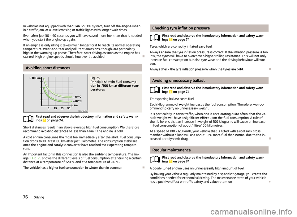
Fig. 75
Principle sketch: Fuel consump-
tion in l/100 km at different tem-
peratures
First read and observe the introductory information and safety warn-
ings on page 74.
Short distances result in an above-average high fuel consumption. We therefore
recommend avoiding distances of less than 4 km if the engine is cold.
A cold engine consumes the most fuel immediately after the start. Fuel consump-tion drops to 10 litres/100 km after just 1 kilometre. The consumption stabilises
once the engine and catalytic converter have reached their operating tempera- ture.
An important factor in this connection is also the ambient temperature. The im-
age » Fig. 75 shows the different levels of fuel consumption after driving a certain
distance at a temperature of +20 °C and at a temperature of -10 °C.
The vehicle has a higher fuel consumption in winter than in summer.
Checking tyre inflation pressure
First read and observe the introductory information and safety warn-ings
on page 74.
Tyres which are correctly inflated save fuel.
Always ensure the tyre inflation pressure is correct. If the inflation pressure is too
low, the tyres will have to overcome a higher rolling resistance. This will not only increase fuel consumption but also tyre wear and the driving behaviour will wor-
sen.
Always check the tyre inflation pressure when the tyres are cold.
Avoiding unnecessary ballast
First read and observe the introductory information and safety warn-
ings
on page 74.
Transporting ballast costs fuel.
Each kilogramme of weight increases the fuel consumption. Therefore, we rec-
ommend to carry no unnecessary weight.
It is particularly in town traffic, when one is accelerating quite often, that the ve-
hicle weight will have a significant effect upon the fuel consumption. A rule of
thumb here is that an increase in weight of 100 kilograms will cause an increase in fuel consumption of about 1 litre/100 kilometres.
At a speed of 100 - 120 km/h, your vehicle that is fitted with a roof rack crossmember without a load will use about 10 % more fuel than normal due to the in-
creased aerodynamic drag.
Regular maintenance
First read and observe the introductory information and safety warn-
ings
on page 74.
A poorly tuned engine uses an unnecessarily high amount of fuel.
By having your vehicle regularly maintained by a specialist garage, you create the conditions needed for economical driving. The maintenance state of your vehicle has a positive effect on traffic safety and value retention
76Driving
Page 83 of 176
Assist systems
Brake assist systems
Introduction
This chapter contains information on the following subjects:
Electronic Stability Control (ESC)
80
Antilock Braking System (ABS)
81
Traction Control System (TCS)
81
Electronic Differential Lock (EDL)
81WARNING■ A lack of fuel can cause irregular engine running or cause the engine to shut
down. The brake assist systems would then fail to function – risk of accident!■
Adjust the speed and driving style to the current visibility, weather, road and
traffic conditions. The increased safety provided by the brake assist systems
must not tempt you to take safety risks – risk of accident!
■
In the event of an ABS fault, visit a specialist garage immediately. Adjust
your style of driving according to the damage to the ABS, as you will not know
the exact extent of the damage or the extent to which this is limiting the
braking efficiency.
CAUTION
■ All four wheels must be fitted with the same tyres approved by the manufactur-
er to ensure the brake assist systems operate correctly.■
Changes to the vehicle (e.g. to the engine, brakes, chassis) can influence the
functionality of the brake assist systems » page 110, Modifications, adjustments
and technical alterations .
■
If a fault occurs in the ABS system, the ESC, ASR and EDL will also fail to work.
An ABS fault is indicated with the warning light » page 19 .
Electronic Stability Control (ESC)
First read and observe the introductory information and safety warn-
ings
on page 80.
The ESC system helps improve control of the vehicle in situations where it is be-
ing operated at its dynamic limits, such as a sudden change to the direction of
travel. Depending on the conditions of the road surface, the risk of skidding is re-
duced, thereby improving the vehicle's driving stability .
The ESC system is automatically activated each time the ignition is switched on.The direction which the driver wishes to take is determined based on the steering angle and the speed of the vehicle and is constantly compared with the actualbehaviour of the vehicle. In the event of deviations, such as the car beginning to
skid, the ESC system will automatically brake the appropriate wheel.
During an intervention of the system, the warning light
flashes in the instru-
ment cluster.
The following systems are integrated into the electronic stabilisation control
(ESC) :
› Antilock brake system (ABS),
› Traction control (TCS);
› Electronic Differential Lock (EDL)
› Hydraulic Brake Assist (HBA)
› Hill Hold Control (HHC).
In the event of an ESC fault, the ESC warning light
illuminates in the instru-
ment cluster » page 18.
Hydraulic Brake Assist (HBA)
HBA increases the braking effect and helps to shorten the braking distance.
The HBA is activated by very quick operation of the brake pedal. In order to ach-
ieve the shortest possible braking distance, the brake pedal must be applied firm-
ly until the vehicle has come to a standstill.
The HBA function is automatically switched off when the brake pedal is released. The ABS is activated faster and more effectively with the intervention of the HBA.
Hill Hold Control (HHC)
When driving on slopes, HHC allows you to move your foot from the brake pedal to the accelerator pedal without having to use the handbrake.
The system holds the brake pressure produced by the activation of the brakepedal for approx. 2 seconds after the brake pedal is released.
80Driving
Page 127 of 176
Regular gas system checks125Safe natural gas126
Natural gas quality and consumption
126
CNG labels
126WARNING■When operating a CNG-powered vehicle, the national legal requirements
must be observed.■
If a fault occurs or a leak in the natural gas system is suspected or if you
smell gas, proceed as follows: ■Stop immediately and switch off the ignition (this will close the solenoid
valves on the natural gas tanks automatically);
■ Open the doors to ventilate the vehicle sufficiently;
■ Immediately extinguish cigarettes, and remove and switch off other spark-
or fire-causing objects from the vehicle immediately. ■ Seek help from a specialist garage to correct the gas system fault.
■
The following are considered faults on the gas system:
■ Gas leakage from any part of the gas system as well as an error on the
ventilation system.
■ Continuous gas venting through the safety valves.
■ Cracks or damage that could result in a gas leak.
■ Fault in the reduction device, the pressure regulator, gas mixer or in the
injection valves, the pressure gauge, the shut-off or check valves and tank
fixtures.
■ If gas flows into the gas mixer or into the injection valves though the en-
gine is stopped.
■ Exceeding the permissible limits for contaminants in the exhaust gas.
■
Regular gas system checks must be carried out in order to operate a natural
gas vehicle. The vehicle owner is responsible for properly conducted tests.
■
The natural gas tanks must not be exposed to a heat source.
■
Always switch off the ignition in case of an accident or vehicle fire!
■
It is prohibited to drive into automatic car washes, enclosed storage places,
garages and similar areas where it is specifically forbidden to enter with CNG vehicles.
RefuellingFig. 100
Fuel filler
First read and observe the introductory information and safety warn-ings on page 123.
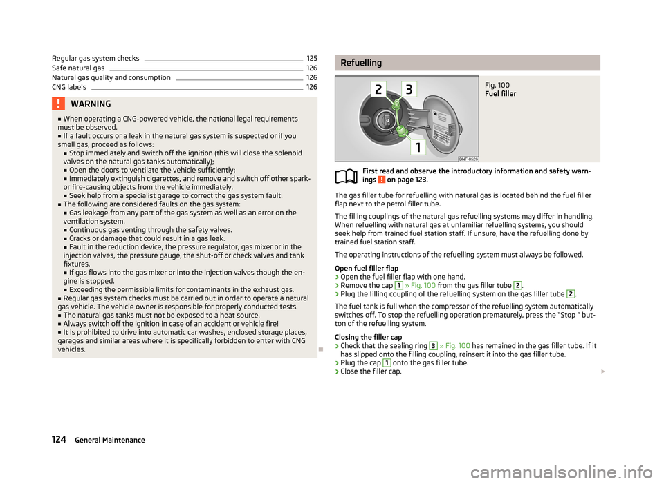
The gas filler tube for refuelling with natural gas is located behind the fuel filler
flap next to the petrol filler tube.
The filling couplings of the natural gas refuelling systems may differ in handling.
When refuelling with natural gas at unfamiliar refuelling systems, you should
seek help from trained fuel station staff. If unsure, have the refuelling done by
trained fuel station staff.
The operating instructions of the refuelling system must always be followed.
Open fuel filler flap
›
Open the fuel filler flap with one hand.
›
Remove the cap
1
» Fig. 100 from the gas filler tube
2
.
›
Plug the filling coupling of the refuelling system on the gas filler tube
2
.
The fuel tank is full when the compressor of the refuelling system automatically
switches off. To stop the refuelling operation prematurely, press the “Stop ” but-
ton of the refuelling system.
Closing the filler cap
›
Check that the sealing ring
3
» Fig. 100 has remained in the gas filler tube. If it
has slipped onto the filling coupling, reinsert it into the gas filler tube.
›
Plug the cap
1
onto the gas filler tube.
›
Close the filler cap.
124General Maintenance
Page 128 of 176
In the following situation, it is possible that the tank cannot be fully filled with
natural gas.
› At very high ambient temperatures. The natural gas refuelling systems have
overheating protection. When the ambient temperature reaches a predefined value, the refuelling system automatically switches off.
› If the refuelling system has been in operation for a longer period, the filling
pressure of the natural gas refuelling system slightly drops.WARNING■ Stop the engine before refuelling.■Always switch off your mobile phone, do not smoke and do not use open
flames when refuelling with natural gas – risk of explosion!■
When refuelling, never get into the vehicle. If you have to get into your vehi-
cle in exceptional cases, close the door and touch a metal surface before you
touch the filling coupling again. This will avoid electrostatic discharges, which
may generate sparks. Sparks can cause a fire during refuelling.
■
Natural gas is highly explosive and flammable. Incorrect refuelling or improp-
er handling of natural gas can cause a fire, an explosion and injuries.
Note
■ The natural gas system of your vehicle is suitable both for fuelling from small
compressors (slow fuelling) and for fuelling from natural gas stations with large
compressors (quick fuelling).■
Noises that occur during refuelling represent no risk.
■
If the vehicle is parked for a longer period of time immediately after refuelling,
the situation may arise in which the pointer of the fuel tank gauge does not indi- cate exactly the same level as was the case immediately after refuelling when theengine is restarted. This is not due to any system leakages but a drop in pressurein the natural gas fuel tank due to technical reasons after a cooling phase directly
after refuelling.
■
For frequent short-haul traffic, especially at low outside temperatures, the vehi-
cle is driven more frequently in petrol mode than in natural gas mode. This is why the petrol tank runs empty faster than the natural gas tank.
■
The capacity of the natural gas tank is about 11 kg, of which about 1.5 kg are a
reserve.
■
The capacity of the petrol tank is about 10 l, of which about 5 l are a reserve.
Automatic switching from CNG to petrol mode
First read and observe the introductory information and safety warn-
ings
on page 123.
The vehicle automatically switches over from CNG mode to petrol mode when the following conditions are met:
› when starting the engine, if the coolant temperature is below 15 °C,
› when the natural gas tank is empty,
› after refuelling with natural gas.
Natural gas as fuel
First read and observe the introductory information and safety warn-ings
on page 123.
Natural gas is an alternative fuel for motor vehicles. Its main component is meth-
ane (CH 4). The rest is carbon dioxide and lower hydrocarbons.
The strict legal requirements for exhaust emissions of motor vehicles are decisive for the current significance of natural gas. In direct comparison to all other fossil
fuels, natural gas is one of the fuels which cause the lowest emissions.
Natural gas is odourless and lighter than air. For safety reasons, it is saturated
with odorous substances, so that is perceived even in very small amounts.
Regular gas system checks
First read and observe the introductory information and safety warn-ings
on page 123.
Every two years, the following inspections must be carried out:
› Check the condition of the fuel filler cap, filler neck and sealing ring, and clean
sealing ring if necessary.
› Check gas system for leaks.
The following checks must be carried out every four years: › Check gas tank mounting for secure attachment and possible damage.
The gas tank must be filled prior to the regular gas system check.
125Inspecting and replenishing
Page 129 of 176
Safe natural gasFirst read and observe the introductory information and safety warn-ings
on page 123.
The safety concept of the natural gas system ensures safe operation. It is equip-
ped with the following security features.
› At each natural gas tank, there is a solenoid valve that closes automatically af-
ter turning off the ignition or when running in petrol mode.
› A thermal fuse prevents uncontrolled rise in pressure in the natural gas tank in
case of fire.
› A flow limiter prevents sudden emptying of the natural gas tank in case the
pressure system is damaged.
› All the attachment points and materials are designed for maximum safety.
Natural gas quality and consumption
First read and observe the introductory information and safety warn-ings
on page 123.
Natural gas is divided into quality groups H-gas and L-gas. The two types of gas
are subdivided according to their calorific value and nitrogen and carbon dioxide
contents. H-gas has a higher calorific value and lower nitrogen or carbon dioxide
content than L-gas.
The higher the calorific value of natural gas, the lower is the consumption. How-
ever, the calorific value and the nitrogen and carbon dioxide contents can vary
within a quality group. Therefore, the consumption of the vehicle may even vary
when driving with only one natural gas quality (either only H-gas or L-gas).
The engine control of your vehicle automatically adjusts to the different natural
gas qualities. Therefore both natural gas qualities can be mixed in the fuel tank. It is therefore not necessary to run the natural gas tank completely empty to fill up
another quality.
CNG labelsFig. 101
CNG label
Fig. 102
Position of the CNG label
First read and observe the introductory information and safety warn-
ings on page 123.
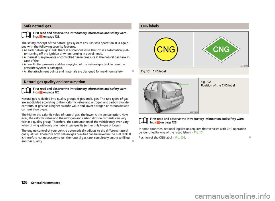
In some countries, national legislation requires that vehicles with CNG operation
be identified by one of the listed labels » Fig. 101.
Position of the CNG label » Fig. 102.
126General Maintenance
Page 142 of 176
WARNINGObserve the following information regarding the wheel bolts.■The wheel bolts must be clean and must turn easily. Never apply grease or
oil.■
The prescribed tightening torque for the wheel bolts is 110 Nm for steel and
light alloy wheel rims.
■
If the wheel bolts are tightened to an insufficient tightening torque, the
rims may come loose when the car is moving – risk of accident! A tightening
torque which is too high can damage the bolts and threads and this can result
in permanent deformation of the contact surfaces on the rim.
■
If the wheel bolts are handled incorrectly, the wheel may come loose when
the car is moving – risk of accident!
WARNINGObserve the following information regarding the spare wheel.■Only use the spare wheel for as long as is necessary.■
Never drive with more than one spare wheel attached.
■
The snow chains cannot be used on the spare wheel.
CAUTION
■ If a spare wheel is used that is not identical to the fitted tyres, the following
must be observed » page 141, Spare wheel .■
Protect the tyres from contact with oil, grease and fuel.
■
Replace lost valve caps.
■
If, in the event of a puncture, it is necessary to fit a spare wheel with a tyre
without a dedicated running direction or with the opposite direction of rotation, drive carefully as the optimal characteristics of the tyre are no longer applicable in
this situation.
For the sake of the environment
Tyres that are insufficiently inflated increase your fuel consumption.
Note
■ We recommend that any work on the wheels or tyres be carried out by a spe-
cialist garage.■
We recommend that you use wheel rims, tyres, full wheel trims and snow chains
from ŠKODA Original Accessories.
Service life of tyresFig. 111
Schematic diagram: Tyre tread with wear indicators/open fuel filler
flap with a table detailing the tyre sizes and tyre inflation pressures
Fig. 112
Replacing wheels
First read and observe the introductory information and safety warn-
ings on page 138.
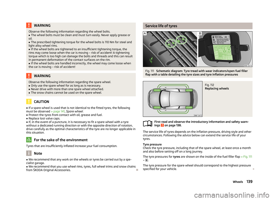
The service life of tyres depends on the inflation pressure, driving style and other
circumstances. Following the advice below can extend the service life of your
tyres.
Tyre pressure
Check the tyre pressure, including that of the spare wheel, at least once a month and also before setting off on a long journey.
The tyre pressures for tyres are shown on the inside of the fuel filler flap » Fig. 111
– .
The tyre pressure for the spare wheel should correspond to the highest pressure
specified for your vehicle.
139Wheels
Page 153 of 176
›Firmly screw the inflation hose 3 onto the tyre inflator bottle 10 clockwise.
The film on the cap is pierced automatically.›
Remove the plug from the inflation hose
3
and plug the open end fully onto
the tyre valve.
›
Hold the bottle
10
with the bottom facing upwards and fill all of the sealing
agent from the tyre inflator bottle into the tyre.
›
Remove the empty tyre inflator bottle from the valve.
›
Screw the valve core back into the tyre valve using the valve remover
1
.
Inflating
›
Screw the tyre inflation hose
5
» Fig. 120 on page 149 of the air compressor
firmly onto the tyre valve.
›
Check that the air release valve
7
is closed.
›
Start the engine and run it in idle.
›
Plug the connector
9
into 12 Volt socket » page 52, 12-volt power socket .
›
Switch on the air compressor with the ON and OFF switch
8
.
›
Allow the air compressor to run until a pressure of 2.0 - 2.5 bar is achieved. Max-
imum run time of 8 minutes » !
›
Switch off the air compressor.
›
If you cannot reach an air pressure of 2.0 – 2.5 bar, unscrew the tyre inflation
hose
5
from the tyre valve.
›
Drive the vehicle 10 metres forwards or backwards to allow the sealing agent to
“distribute” in the tyre.
›
Firmly screw the tyre inflation hose
5
back onto the tyre valve and repeat the
inflation process.
›
If you cannot reach the required tyre inflation pressure here either, this means
the tyre has sustained too much damage. You cannot seal with tyre with the
breakdown kit »
.
›
Switch off the air compressor.
›
Remove the tyre inflation hose
5
from the tyre valve.
Once a tyre inflation pressure of 2.0 – 2.5 bar is achieved, continue the journey at
a maximum speed of 80 km/h (50 mph).
Check the tyre inflation pressure after driving for 10 minutes » page 150.
WARNING■
The tyre inflation hose and air compressor may get hot as the tyre is being
inflated – there is a risk of injury.■
Do not place the hot tyre inflation hose or hot air compressor on flammable
materials – there is a risk of fire.
■
If you cannot inflate the tyre to at least 2.0 bar, this means the damage sus-
tained was too serious. The sealing agent cannot be used to seal the tyre.
Do not drive the vehicle. Seek help from a specialist garage.
CAUTION
Switch off the air compressor after running 8 minutes at the latest – there is a
risk of overheating. Allow the air compressor to cool a few minutes before switch- ing it on again.
Check after 10 minutes' driving
First read and observe the introductory information and safety warn-ings
on page 148.
Check the tyre inflation pressure after driving for 10 minutes!
If the tyre pressure is 1.3 bar or less
›
Do not drive the vehicle! You cannot properly seal with tyre with the break-
down kit.
If the tyre pressure is 1.3 bar or more
›
Adjust the tyre inflation pressure to the correct value (see inside of fuel filler cap).
›
Continue driving carefully to the nearest specialist garage at a maximum speed
of 80 km/h (50 mph).
Jump-starting
Introduction
This chapter contains information on the following subjects:
Jump-starting using the battery from another vehicle
151
Jump-starting in vehicles with the START-STOP system
152
150Do-it-yourself
Page 168 of 176
Oil level131
Windscreen washer fluid129
Children and safety103
Child safety Side airbag
104
Child safety lock23
Child seat Classification
105
ISOFIX106
on the front passenger seat104
TOP TETHER107
Use of child seats105
Use of ISOFIX child seats106
Chrome parts refer to Taking care of your vehicle
116
Cigarette lighter52
City Safe Drive86
Warning light21
Cleaning108
Alcantara120
Artificial leather120
cloths120
Covers of electrically heated seats120
Headlight lenses117
Natural leather119
Plastic parts116
Wheels118
Clock14
Clothes hooks53
CNG123
Checking125
Fuel gauge11
Labels126
Natural gas as fuel125
Quality126
Refuelling124
Safe fuel126
Switching from CNG to petrol mode125
Cockpit 12-volt power socket
52
Ash tray51
Cigarette lighter52
Cup holder51
General view9
Light36, 37
Storage compartments53
Compartments53
Compressed natural gas See CNG
123
Computer see multifunction display
13
Coolant132
Checking132
Replenishing133
Warning light18
Correct seated position91
Driver92
Front passenger92
Instructions92
Rear seats92
Counter for distance driven12
Cruise Control System83
Cup holder51
D
DAY LIGHT Daytime running light
34
Daytime running light34
Deactivating an airbag101
Decorative films116
Defrosting rear window37
Delayed locking of the boot lid see Boot lid
29
Digital clock14
Dipstick131
Disconnecting and reconnecting vehicle battery
137
Display Service interval
12
Distance driven12
Door Child safety lock23
Closing24
Opening24
Door opening lever locking of
24
Door opening leverl unlocking of
24
Doors Emergency locking
25
Driving Abroad
79
Driving through water on streets78
Emissions161
Fuel consumption161
Trailer operation113
Driving economically Economical gear changing
75
Driving through water78
E
Economical and environmentally friendly driving
74
Economical driving Ballast
76
Driving at full throttle75
Idling75
Looking ahead75
Regular maintenance76
Saving energy77
Short distances76
Tyre inflation pressure76
EDS81
Electrical power windows Button in the driver's door
30
Electronic Differential Lock81
Electronic immobilizer68
Emergency Changing a wheel
145
Hazard warning light system36
jump-starting151
165Index