radio SKODA CITIGO 2013 1.G Owner's Manual
[x] Cancel search | Manufacturer: SKODA, Model Year: 2013, Model line: CITIGO, Model: SKODA CITIGO 2013 1.GPages: 176, PDF Size: 10.54 MB
Page 12 of 176
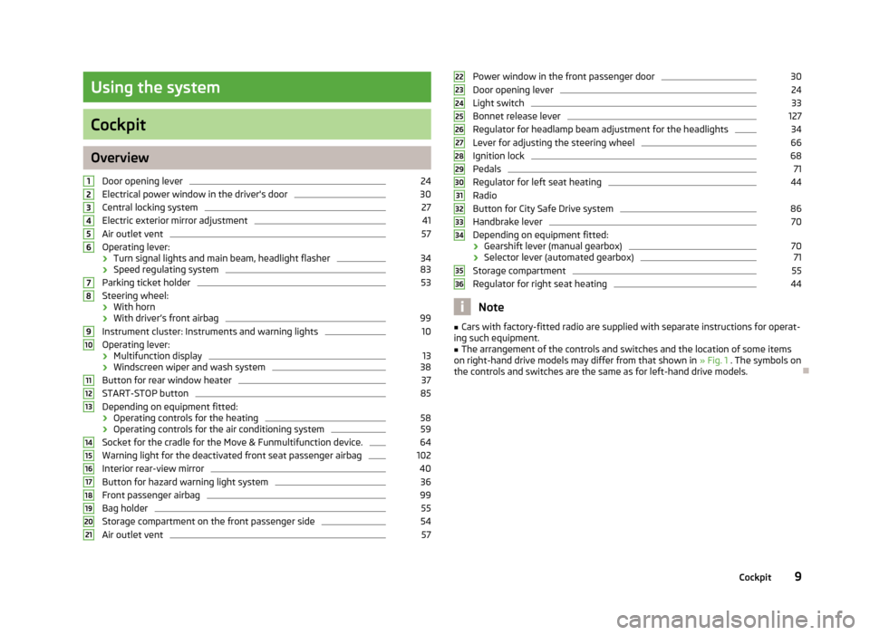
Using the system
Cockpit
OverviewDoor opening lever
24
Electrical power window in the driver's door
30
Central locking system
27
Electric exterior mirror adjustment
41
Air outlet vent
57
Operating lever:
› Turn signal lights and main beam, headlight flasher
34
›
Speed regulating system
83
Parking ticket holder
53
Steering wheel:
› With horn
› With driver’s front airbag
99
Instrument cluster: Instruments and warning lights
10
Operating lever:
› Multifunction display
13
›Windscreen wiper and wash system
38
Button for rear window heater
37
START-STOP button
85
Depending on equipment fitted:
› Operating controls for the heating
58
›Operating controls for the air conditioning system
59
Socket for the cradle for the Move & Funmultifunction device.
64
Warning light for the deactivated front seat passenger airbag
102
Interior rear-view mirror
40
Button for hazard warning light system
36
Front passenger airbag
99
Bag holder
55
Storage compartment on the front passenger side
54
Air outlet vent
57123456789101112131415161718192021Power window in the front passenger door30Door opening lever24
Light switch
33
Bonnet release lever
127
Regulator for headlamp beam adjustment for the headlights
34
Lever for adjusting the steering wheel
66
Ignition lock
68
Pedals
71
Regulator for left seat heating
44
Radio
Button for City Safe Drive system
86
Handbrake lever
70
Depending on equipment fitted:
› Gearshift lever (manual gearbox)
70
›
Selector lever (automated gearbox)
71
Storage compartment
55
Regulator for right seat heating
44
Note
■
Cars with factory-fitted radio are supplied with separate instructions for operat-
ing such equipment.■
The arrangement of the controls and switches and the location of some items
on right-hand drive models may differ from that shown in » Fig. 1 . The symbols on
the controls and switches are the same as for left-hand drive models.
2223242526272829303132333435369Cockpit
Page 66 of 176
Communication and multimedia
Telephone and Move & Fun
Introduction
This chapter contains information on the following subjects:
Mobile phones and two-way radio systems
63
Multifunction deviceMove & Fun
64
Mobile phones and two-way radio systems
First read and observe the introductory information given on page 63.
ŠKODA permits the operation of mobile phones and two-way radio systems with
a professionally installed external aerial and a maximum transmission power of
up to 10 watts.
Please consult a ŠKODA Partner for information about the possibility of installing
and operating mobile phones and two-way radio systems with a transmission
power of more than 10 W.
Operating mobile phones or two-way radio systems may interfere with the func-tionality of the electronic systems in your vehicle.
The possible reasons for this are. › no external aerial.
› external aerial incorrectly installed.
› transmission power greater than 10 watts.
WARNING■
Concentrate fully at all times on your driving! As the driver you are fully re-
sponsible for the operation of your vehicle. Use the telephone system only to such an extent that you are in full control of your vehicle at any time.■
The national regulations for using a mobile phone in a vehicle must be ob-
served.
WARNING (Continued)■ If a mobile phone or a two-way radio system is operated in a vehicle without
an external aerial or an external aerial which has been installed incorrectly,
this can increase the strength of the electromagnetic field inside the vehicle.■
Two-way radio systems, mobile phones or mounts must not be installed on
airbag covers or within the immediate deployment range of the airbags.
■
Never leave a mobile phone on a seat, on the dash panel or in another area
from which it can be thrown during a sudden braking manoeuvre, an accident
or a collision — risk of injury.
Note
■ We recommend that the installation of mobile phones and two-way radio sys-
tems in a vehicle be carried out by a specialist garage.■
The range of the Bluetooth ®
connection to the hands-free system is restricted
to the vehicle interior. The range is dependent on local factors, e.g. obstacles be- tween the devices and mutual interferences with other devices. If your mobile phone is in a jacket pocket, for example, this can lead to difficulties when estab-
lishing a connection with the hands-free-system or transferring data.
63Communication and multimedia
Page 67 of 176
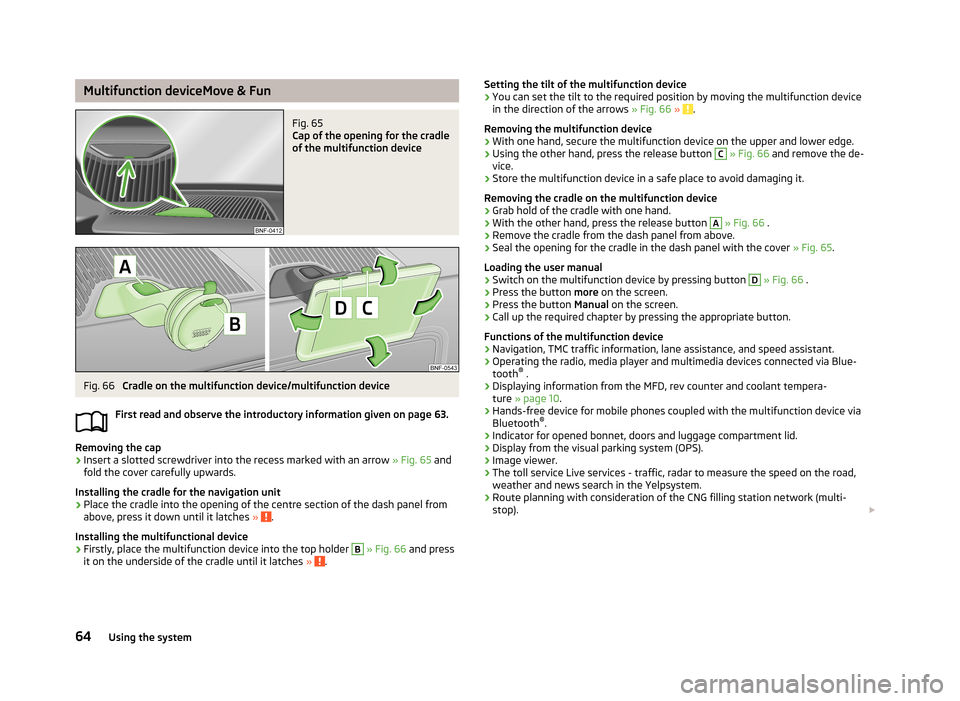
Multifunction deviceMove & FunFig. 65
Cap of the opening for the cradle
of the multifunction device
Fig. 66
Cradle on the multifunction device/multifunction device
First read and observe the introductory information given on page 63.
Removing the cap
›
Insert a slotted screwdriver into the recess marked with an arrow » Fig. 65 and
fold the cover carefully upwards.
Installing the cradle for the navigation unit
›
Place the cradle into the opening of the centre section of the dash panel from above, press it down until it latches » .
Installing the multifunctional device
›
Firstly, place the multifunction device into the top holder
B
» Fig. 66 and press
it on the underside of the cradle until it latches » .
Setting the tilt of the multifunction device›You can set the tilt to the required position by moving the multifunction device
in the direction of the arrows » Fig. 66 » .
Removing the multifunction device
›
With one hand, secure the multifunction device on the upper and lower edge.
›
Using the other hand, press the release button
C
» Fig. 66 and remove the de-
vice.
›
Store the multifunction device in a safe place to avoid damaging it.
Removing the cradle on the multifunction device
›
Grab hold of the cradle with one hand.
›
With the other hand, press the release button
A
» Fig. 66 .
›
Remove the cradle from the dash panel from above.
›
Seal the opening for the cradle in the dash panel with the cover » Fig. 65.
Loading the user manual
›
Switch on the multifunction device by pressing button
D
» Fig. 66 .
›
Press the button more on the screen.
›
Press the button Manual on the screen.
›
Call up the required chapter by pressing the appropriate button.
Functions of the multifunction device
› Navigation, TMC traffic information, lane assistance, and speed assistant.
› Operating the radio, media player and multimedia devices connected via Blue-
tooth ®
.
› Displaying information from the MFD, rev counter and coolant tempera-
ture » page 10 .
› Hands-free device for mobile phones coupled with the multifunction device via
Bluetooth ®
.
› Indicator for opened bonnet, doors and luggage compartment lid.
› Display from the visual parking system (OPS).
› Image viewer.
› The toll service Live services - traffic, radar to measure the speed on the road,
weather and news search in the Yelpsystem.
› Route planning with consideration of the CNG filling station network (multi-
stop).
64Using the system
Page 117 of 176
WARNING■When washing your vehicle in the winter: Water and ice in the braking sys-
tem can affect the braking efficiency – risk of accident!■
Only wash the vehicle when the ignition is switched off – risk of accident!
CAUTION
Do not wash your vehicle in bright sunlight – risk of paint damage.
For the sake of the environment
Only wash the vehicle at washing bays intended for this purpose.
Washing by hand
First read and observe the introductory information and safety warn-
ings
on page 113.
Soak the dirt with plenty of water and rinse as well as possible.
Clean the vehicle with a soft sponge, a washing glove or a washing brush . Work
from the top to the bottom – starting with the roof.
Only use a car shampoo for stubborn dirt.
Wash out the sponge or washing glove thoroughly at short intervals.
Clean wheels, door sills and similar parts last. Use a second sponge for such
areas.
Give the vehicle a good rinse after washing it and dry it off using a chamois leath- er.
CAUTION
■ When washing the car by hand, protect your hands and arms from sharp-edged
metal parts (e.g. when cleaning the underfloor, the inside of the wheel housings
or the wheel trims, etc.) - There is a risk of cuts!■
Only apply slight pressure when cleaning the vehicle's paintwork.
Automatic car wash systems
First read and observe the introductory information and safety warn-
ings
on page 113.
The usual precautionary measures must be taken before washing the vehicle in
an automatic car wash system (e.g. closing the windows and the sliding/tilting
roof etc.).
If your vehicle is fitted with any particular attached parts, such as a spoiler, roof
rack system, two-way radio aerial etc., it is best to consult the operator of the car
wash system beforehand.
After an automatic wash with wax treatment, the lips of the wipers should be cleaned with cleaning agents specially designed for the purpose, and then de-
greased.
WARNINGFold in the exterior mirrors to prevent damage before washing the vehicle in
an automatic car wash system.
Washing with a high-pressure cleaner
First read and observe the introductory information and safety warn-
ings
on page 113.
When washing the vehicle with a high-pressure cleaner, the instructions for use
of the equipment must be observed. This applies in particular to the pressure
used and to the spraying distance .
Maintain a sufficiently large distance to the parking aid sensors and soft materials
such as rubber hoses or insulation material.
WARNINGNever use circular spray nozzles or dirt cutters! 114General Maintenance
Page 140 of 176
ReplaceFirst read and observe the introductory information and safety warn-
ings
on page 134.
When replacing a battery, the new vehicle battery must have the same capacity,
voltage, amperage and be the same size. Suitable vehicle battery types can be purchased from a specialist garage.
We recommend having the battery replaced by a specialist garage, where the
new vehicle battery will be installed properly and the original battery will be dis-
posed of in accordance with national regulations.
Disconnecting and reconnecting
First read and observe the introductory information and safety warn-
ings
on page 134.
On disconnecting and reconnecting the vehicle battery the following functions
are initially deactivated or are no longer able to operate fault-free:
OperationOperating measureEnter radio code number» Radio manualSetting the clock» page 14Data in the multifunction display are deleted.» page 13
Note
We recommend having the vehicle checked by a specialist garage in order to en-
sure full functionality of all electrical systems.
Automatic load deactivation
First read and observe the introductory information and safety warn-ings
on page 134.
The vehicle voltage control unit automatically prevents the battery from discharg-
ing when the battery is put under high levels of strain. This manifests itself by the following.
› The idling speed is raised to allow the generator to deliver more electricity to
the electrical system.
› Where necessary, large convenience consumers such as seat heaters and rear
window heaters have their power limited or are shut off completely in the event of an emergency.
CAUTION
■ Despite such intervention by the vehicle electric system management, the vehi-
cle battery may be drained. For example, when the ignition is switched on a long
time with the engine turned off or the side or parking lights are turned on during longer parking.■
Consumers that are supplied via a 12-V power socket can cause the vehicle bat-
tery to discharge when the ignition is switched off.
Note
Driving comfort is not impaired by consumers being deactivated. The driver is of-
ten not aware of it having taken place.
137Inspecting and replenishing
Page 158 of 176
Replacing fuses›Press the button 1 » Fig. 124 .›
Push the lid in the direction of the arrow.
›2
Remove the bracket.
›
Place the bracket on the respective fuse and pull this out.
›
Insert a new fuse.
›
Replace the bracket at the original position.
›
Fold the cover upwards against the direction of the arrow.
›
Close the cover until it clicks into place.
Fuse assignment on the underside of the dash panel
No.Power consumer1Telephone, radiator fan, instrument cluster, engine control unit2Diagnostic port, air compressor, bar with buttons, control unit for air
conditioning3Clutch pedal switch, brake pedal switch4Switch illumination, number plate light5Steering column switch, central control unit6Headlamp beam adjustment, exterior mirror adjustment7-8Automated transmission9Airbag, bar with buttons10Park Assist11Headlights12The rear fog light13Headlights14Rear window wiper15Light switch16Steering force assistance17Windscreen washer18Reverse light switch19Injection valves, coolant pump20ABS/ESP21Parking lights,22Daytime running lights23Headlights24FlasherNo.Power consumer25Windscreen Wiper and Washer System26Not assigned27Interior lighting28Diagnostic connector29Central control unit30Exterior mirror heater31Radiator fan, lambda probe32Blinking light, brake light, daytime running lights, rear light33Main beam34Main beam35Fuel pump36Cigarette lighter, 12-volt power socket37Air blower for heating and air conditioning38Radio39Panoramic sliding roof, horn40Engine control unit41Central locking system42Ignition module43Seat heaters44Fuel pump45Light switch46Rear window heater47Windows48Horn49Windscreen wipers50Fog lights, headlight51Power windows
155Fuses and light bulbs
Page 159 of 176
Fuses in the engine compartmentFig. 125
Distribution board cover/fuses
First read and observe the introductory information and safety warn-
ings
on page 154.
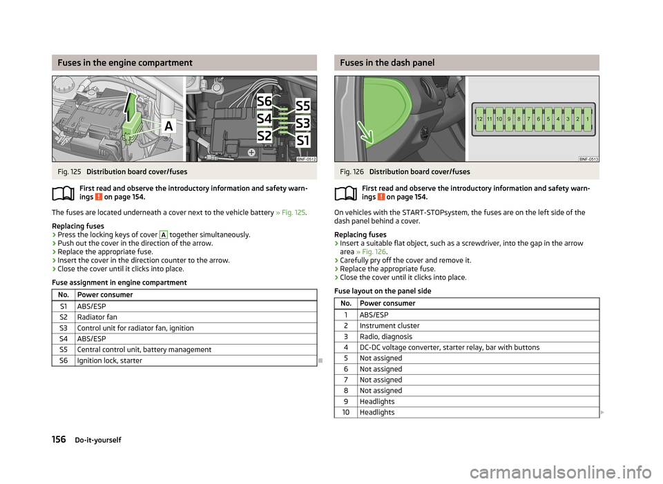
The fuses are located underneath a cover next to the vehicle battery » Fig. 125.
Replacing fuses
›
Press the locking keys of cover
A
together simultaneously.
›
Push out the cover in the direction of the arrow.
›
Replace the appropriate fuse.
›
Insert the cover in the direction counter to the arrow.
›
Close the cover until it clicks into place.
Fuse assignment in engine compartment
No.Power consumerS1ABS/ESPS2Radiator fanS3Control unit for radiator fan, ignitionS4ABS/ESPS5Central control unit, battery managementS6Ignition lock, starter
Fuses in the dash panelFig. 126
Distribution board cover/fuses
First read and observe the introductory information and safety warn-
ings
on page 154.
On vehicles with the START-STOPsystem, the fuses are on the left side of the
dash panel behind a cover.
Replacing fuses
›
Insert a suitable flat object, such as a screwdriver, into the gap in the arrow area » Fig. 126 .
›
Carefully pry off the cover and remove it.
›
Replace the appropriate fuse.
›
Close the cover until it clicks into place.
Fuse layout on the panel side
No.Power consumer1ABS/ESP2Instrument cluster3Radio, diagnosis4DC-DC voltage converter, starter relay, bar with buttons5Not assigned6Not assigned7Not assigned8Not assigned9Headlights10Headlights 156Do-it-yourself
Page 160 of 176
No.Power consumer11Starter12DC-DC voltage converter, ABS, instrument cluster, radio
Bulbs
Introduction
This chapter contains information on the following subjects:
Headlights
157
Replacing the bulb for the side turn signal lights
158
Replacing the bulb for the fog light
158
Replacing the bulb for the licence plate light
159
Tail light
159
Some manual skills are required to change a bulb. For this reason, we recommend
having bulbs replaced by a specialist garage or seeking other expert help in the
event of any uncertainties.
› Switch off the ignition and all of the lights before replacing a bulb.
› Faulty bulbs must only be replaced with the same type of bulbs. The designa-
tion is located on the light socket or the glass bulb.
› A stowage compartment for replacement bulbs is located in a plastic box in the
spare wheel or underneath the floor covering in the luggage compartment.
WARNING■ Always read and observe the warnings before completing any work in the
engine compartment » page 127, Engine compartment .■
Accidents can be caused if the road in front of the vehicle is not sufficiently
illuminated and the vehicle cannot or can only be seen with difficulty by other
road users.
■
The H4 bulb is pressurised and may explode during a bulb replacement - risk
of injury! We therefore recommended wearing gloves and safety glasses when changing a bulb.
CAUTIONDo not take hold of the glass bulb with naked fingers (even the smallest amountof dirt reduces the working life of the light bulb). Use a clean cloth, napkin, or sim-
ilar.
Note
■ This Owner's Manual only describes the replacement of bulbs where it is possi-
ble to replace the bulbs on your own without any complications arising. Other bulbs must be replaced by a specialist garage.■
We recommend that a box of replacement bulbs always be carried in the vehi-
cle. Replacement bulbs can be purchased from ŠKODAOriginal Accessories.
■
We recommend having the headlight settings checked by a specialist garage af-
ter replacing a bulb in the main or low beam.
■
In the case of a defective CD player, visit a specialist garage.
Headlights
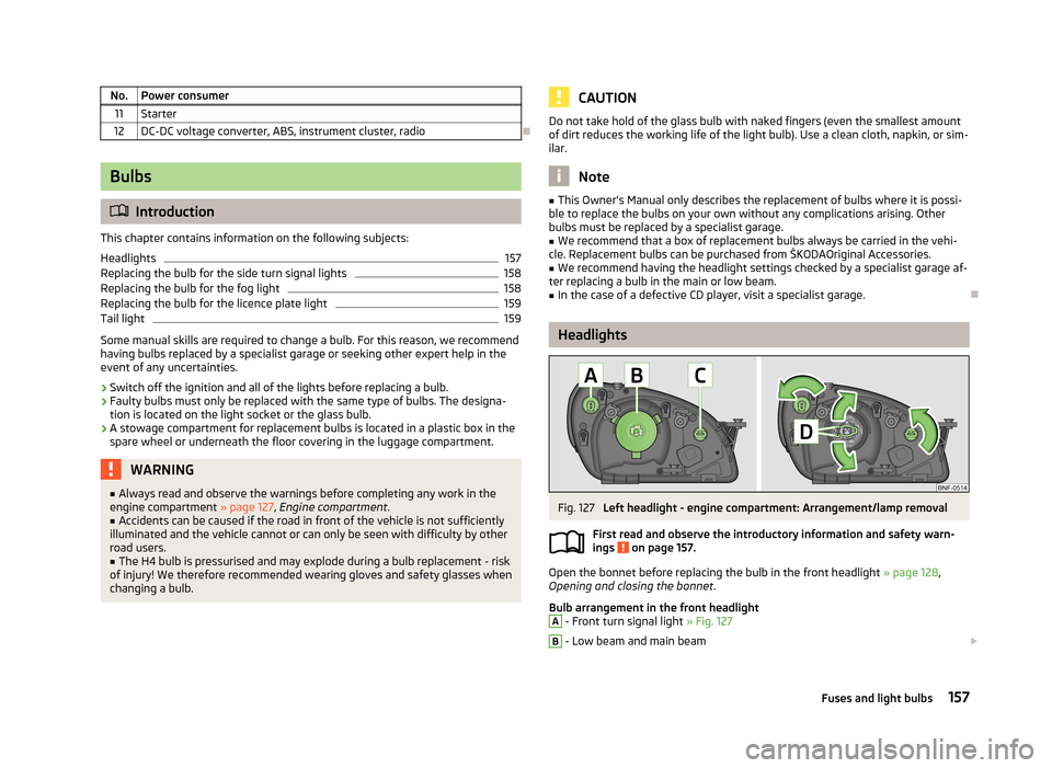
Fig. 127
Left headlight - engine compartment: Arrangement/lamp removal
First read and observe the introductory information and safety warn- ings
on page 157.
Open the bonnet before replacing the bulb in the front headlight » page 128,
Opening and closing the bonnet .
Bulb arrangement in the front headlight
A
- Front turn signal light » Fig. 127
B
- Low beam and main beam
157Fuses and light bulbs
Page 172 of 176
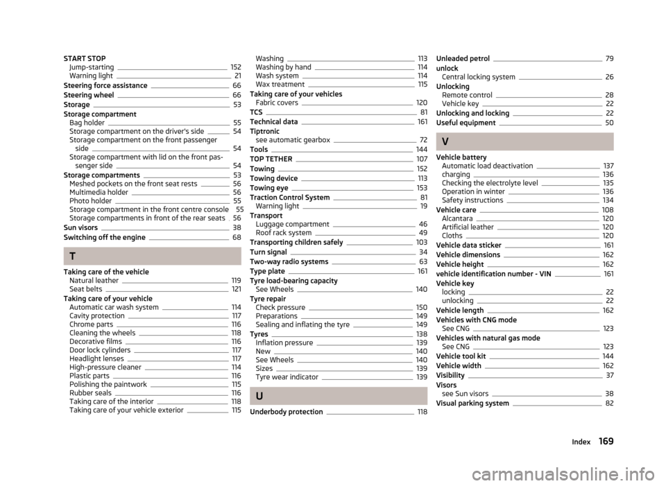
START STOPJump-starting152
Warning light21
Steering force assistance66
Steering wheel66
Storage53
Storage compartment Bag holder
55
Storage compartment on the driver's side54
Storage compartment on the front passenger side
54
Storage compartment with lid on the front pas- senger side
54
Storage compartments53
Meshed pockets on the front seat rests56
Multimedia holder56
Photo holder55
Storage compartment in the front centre console 55 Storage compartments in front of the rear seats
56
Sun visors38
Switching off the engine68
T
Taking care of the vehicle Natural leather
119
Seat belts121
Taking care of your vehicle Automatic car wash system
114
Cavity protection117
Chrome parts116
Cleaning the wheels118
Decorative films116
Door lock cylinders117
Headlight lenses117
High-pressure cleaner114
Plastic parts116
Polishing the paintwork115
Rubber seals116
Taking care of the interior118
Taking care of your vehicle exterior115
Washing113
Washing by hand114
Wash system114
Wax treatment115
Taking care of your vehicles Fabric covers
120
TCS81
Technical data161
Tiptronic see automatic gearbox
72
Tools144
TOP TETHER107
Towing152
Towing device113
Towing eye153
Traction Control System81
Warning light19
Transport Luggage compartment
46
Roof rack system49
Transporting children safely103
Turn signal34
Two-way radio systems63
Type plate161
Tyre load-bearing capacity See Wheels
140
Tyre repair Check pressure
150
Preparations149
Sealing and inflating the tyre149
Tyres138
Inflation pressure139
New140
See Wheels140
Sizes139
Tyre wear indicator139
U
Underbody protection
118
Unleaded petrol79
unlock Central locking system
26
Unlocking Remote control
28
Vehicle key22
Unlocking and locking22
Useful equipment50
V
Vehicle battery Automatic load deactivation
137
charging136
Checking the electrolyte level135
Operation in winter136
Safety instructions134
Vehicle care108
Alcantara120
Artificial leather120
Cloths120
Vehicle data sticker161
Vehicle dimensions162
Vehicle height162
vehicle identification number - VIN161
Vehicle key locking
22
unlocking22
Vehicle length162
Vehicles with CNG mode See CNG
123
Vehicles with natural gas mode See CNG
123
Vehicle tool kit144
Vehicle width162
Visibility37
Visors see Sun visors
38
Visual parking system82
169Index