run flat SKODA CITIGO 2013 1.G Owner's Manual
[x] Cancel search | Manufacturer: SKODA, Model Year: 2013, Model line: CITIGO, Model: SKODA CITIGO 2013 1.GPages: 176, PDF Size: 10.54 MB
Page 77 of 176
With vehicles with a manual gearbox, do not drive at unnecessarily low engine
speeds. Shift down a gear when the engine is no longer running smoothly. Ob-
serve the recommended gear » page 12, Recommended gear .
CAUTION
■
The engine is not protected from excessive engine revs caused by shifting
down at the wrong time. This can result in a sudden increase in revs beyond the
permissible maximum rpm, thereby causing engine damage.■
Never rev up a cold engine when the vehicle is stationary or when driving in in-
dividual gears.
For the sake of the environment
Do not drive at unnecessarily high engine speeds. Shifting up sooner helps save
fuel, reduces engine noise and protects the environment.
New tyres
First read and observe the introductory information given on page 73.
New tyres must firstly be “run in” since they do not offer optimal grip at first.
Therefore, drive especially carefully for the first 500 km or so.
New brake pads
First read and observe the introductory information given on page 73.
New brake pads do not initially provide optimal braking performance. They firstneed to be “run in”. Therefore, drive especially carefully for the first 200 km or so.
Economical driving and environmental sustainability
Introduction
This chapter contains information on the following subjects:
Looking ahead
75
Economical gear changing
75
Avoiding full throttle
75
Reducing idling
75
Avoiding short distances
76
Checking tyre inflation pressure
76
Avoiding unnecessary ballast
76
Regular maintenance
76
Saving electrical energy
77
Environmental compatibility
77
The technical requirements for low fuel usage and economic efficiency of the ve-
hicle have already been built into the vehicle at the works. ŠKODA places a partic-
ular emphasis on minimising negative effects on the environment.
It is necessary to take note of the guidelines given in this chapter in order tomake best use of these characteristics and to maintain their effectiveness.
Fuel consumption, environmental pollution and the wear to the engine, brakes
and tyres depend essentially on the following three factors:
› your personal driving style
› operating conditions
› technical requirements
The fuel economy by can be improved by 10 -15 % by always looking ahead and
driving in an economical way.
Fuel consumption is also be influenced by external factors which are beyond the
driver's control. Consumption increases during the winter or under difficult condi-
tions, on poor roads, etc.
Fuel consumption can vary considerably from the manufacturer's data, as a result
of outside temperatures, weather and driving style.
Such an engine speed should be adhered to when accelerating, in order to avoid a
high fuel consumption and resonance of the vehicle.
74Driving
Page 142 of 176
WARNINGObserve the following information regarding the wheel bolts.■The wheel bolts must be clean and must turn easily. Never apply grease or
oil.■
The prescribed tightening torque for the wheel bolts is 110 Nm for steel and
light alloy wheel rims.
■
If the wheel bolts are tightened to an insufficient tightening torque, the
rims may come loose when the car is moving – risk of accident! A tightening
torque which is too high can damage the bolts and threads and this can result
in permanent deformation of the contact surfaces on the rim.
■
If the wheel bolts are handled incorrectly, the wheel may come loose when
the car is moving – risk of accident!
WARNINGObserve the following information regarding the spare wheel.■Only use the spare wheel for as long as is necessary.■
Never drive with more than one spare wheel attached.
■
The snow chains cannot be used on the spare wheel.
CAUTION
■ If a spare wheel is used that is not identical to the fitted tyres, the following
must be observed » page 141, Spare wheel .■
Protect the tyres from contact with oil, grease and fuel.
■
Replace lost valve caps.
■
If, in the event of a puncture, it is necessary to fit a spare wheel with a tyre
without a dedicated running direction or with the opposite direction of rotation, drive carefully as the optimal characteristics of the tyre are no longer applicable in
this situation.
For the sake of the environment
Tyres that are insufficiently inflated increase your fuel consumption.
Note
■ We recommend that any work on the wheels or tyres be carried out by a spe-
cialist garage.■
We recommend that you use wheel rims, tyres, full wheel trims and snow chains
from ŠKODA Original Accessories.
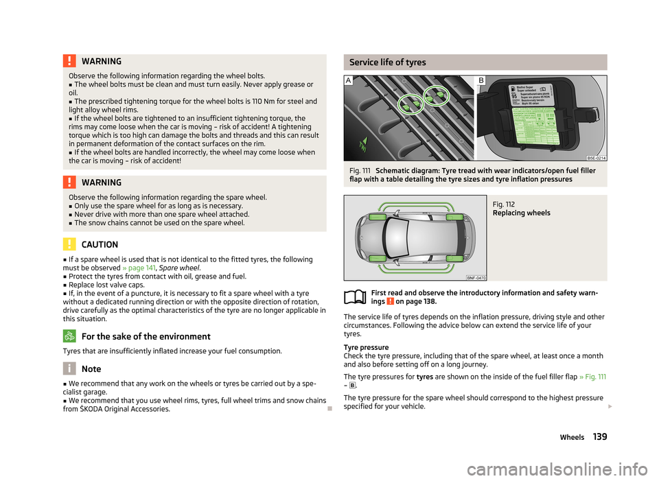
Service life of tyresFig. 111
Schematic diagram: Tyre tread with wear indicators/open fuel filler
flap with a table detailing the tyre sizes and tyre inflation pressures
Fig. 112
Replacing wheels
First read and observe the introductory information and safety warn-
ings on page 138.
The service life of tyres depends on the inflation pressure, driving style and other
circumstances. Following the advice below can extend the service life of your
tyres.
Tyre pressure
Check the tyre pressure, including that of the spare wheel, at least once a month and also before setting off on a long journey.
The tyre pressures for tyres are shown on the inside of the fuel filler flap » Fig. 111
– .
The tyre pressure for the spare wheel should correspond to the highest pressure
specified for your vehicle.
139Wheels
Page 153 of 176
›Firmly screw the inflation hose 3 onto the tyre inflator bottle 10 clockwise.
The film on the cap is pierced automatically.›
Remove the plug from the inflation hose
3
and plug the open end fully onto
the tyre valve.
›
Hold the bottle
10
with the bottom facing upwards and fill all of the sealing
agent from the tyre inflator bottle into the tyre.
›
Remove the empty tyre inflator bottle from the valve.
›
Screw the valve core back into the tyre valve using the valve remover
1
.
Inflating
›
Screw the tyre inflation hose
5
» Fig. 120 on page 149 of the air compressor
firmly onto the tyre valve.
›
Check that the air release valve
7
is closed.
›
Start the engine and run it in idle.
›
Plug the connector
9
into 12 Volt socket » page 52, 12-volt power socket .
›
Switch on the air compressor with the ON and OFF switch
8
.
›
Allow the air compressor to run until a pressure of 2.0 - 2.5 bar is achieved. Max-
imum run time of 8 minutes » !
›
Switch off the air compressor.
›
If you cannot reach an air pressure of 2.0 – 2.5 bar, unscrew the tyre inflation
hose
5
from the tyre valve.
›
Drive the vehicle 10 metres forwards or backwards to allow the sealing agent to
“distribute” in the tyre.
›
Firmly screw the tyre inflation hose
5
back onto the tyre valve and repeat the
inflation process.
›
If you cannot reach the required tyre inflation pressure here either, this means
the tyre has sustained too much damage. You cannot seal with tyre with the
breakdown kit »
.
›
Switch off the air compressor.
›
Remove the tyre inflation hose
5
from the tyre valve.
Once a tyre inflation pressure of 2.0 – 2.5 bar is achieved, continue the journey at
a maximum speed of 80 km/h (50 mph).
Check the tyre inflation pressure after driving for 10 minutes » page 150.
WARNING■
The tyre inflation hose and air compressor may get hot as the tyre is being
inflated – there is a risk of injury.■
Do not place the hot tyre inflation hose or hot air compressor on flammable
materials – there is a risk of fire.
■
If you cannot inflate the tyre to at least 2.0 bar, this means the damage sus-
tained was too serious. The sealing agent cannot be used to seal the tyre.
Do not drive the vehicle. Seek help from a specialist garage.
CAUTION
Switch off the air compressor after running 8 minutes at the latest – there is a
risk of overheating. Allow the air compressor to cool a few minutes before switch- ing it on again.
Check after 10 minutes' driving
First read and observe the introductory information and safety warn-ings
on page 148.
Check the tyre inflation pressure after driving for 10 minutes!
If the tyre pressure is 1.3 bar or less
›
Do not drive the vehicle! You cannot properly seal with tyre with the break-
down kit.
If the tyre pressure is 1.3 bar or more
›
Adjust the tyre inflation pressure to the correct value (see inside of fuel filler cap).
›
Continue driving carefully to the nearest specialist garage at a maximum speed
of 80 km/h (50 mph).
Jump-starting
Introduction
This chapter contains information on the following subjects:
Jump-starting using the battery from another vehicle
151
Jump-starting in vehicles with the START-STOP system
152
150Do-it-yourself
Page 161 of 176
C - Parking and daytime running light
Changing the bulb for the front turn signal light›
Turn the bulb holder
A
» Fig. 127 anti-clockwise up to the stop and remove.
›
Push the faulty bulb into the holder, turn in anti-clockwise up to the stop and
remove.
›
Insert a new bulb into the socket and turn clockwise to the stop.
›
Insert the lamp holder with the new bulb into the headlamp and turn it clock-
wise until it stops.
Replacing the bulb for low beam and main beam
›
Remove the connector on the bulb
B
» Fig. 127 .
›
Remove the rubber cover.
›
Press the circlip
D
in the direction of the headlamp and then unhook in the di-
rection of the arrow.
›
Remove the light bulb and insert a new light bulb in such a way that the fixing lugs of the light bulb socket fit into the recesses at the headlight.
Installation is carried out in the reverse order.
Replacing the bulb for the front parking light and daylight running light
›
Turn the bulb holder
C
» Fig. 127 up to the stop in an anti-clockwise direction
and remove.
›
Remove the faulty bulb from the socket.
›
Insert a new bulb into the socket.
›
Insert the lamp holder with the new bulb into the headlamp and turn it clock-
wise until it stops.
Replacing the bulb for the side turn signal lights
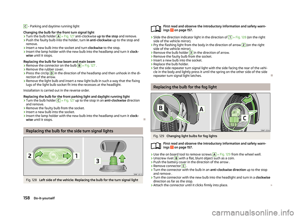
Fig. 128
Left side of the vehicle: Replacing the bulb for the turn signal light
First read and observe the introductory information and safety warn-
ings on page 157.›
Slide the direction indicator light in the direction of
1
» Fig. 128 (on the right
side of the vehicle mirror).
›
Pry the flashing light from the body in the direction of arrow
2
(on the right
side of the vehicle mirror).
›
Remove the bulb holder
3
in the direction of arrow.
›
Remove the faulty bulb from the socket.
›
Insert a new bulb into the socket.
›
Replace the bulb holder.
›
Set the side repeater turn signal light with the side facing the rear of the vehi- cle in the body and lightly press it until the spring on the other side of the side
repeater turn signal light latches.
Replacing the bulb for the fog light
Fig. 129
Changing light bulbs for fog lights
First read and observe the introductory information and safety warn- ings
on page 157.
›
Use the on board tool to remove screws
A
» Fig. 129 from the wheel well.
›
Unscrew rivet
B
with a flat, blunt object such as a coin.
›
Push the battery cover in the direction of the arrow .
›
Remove connector
C
.
›
Turn the connector with the bulb in an anti-clockwise direction up to the stop
and remove .
›
Turn the connector with the new bulb into the headlight and turn in a clockwise
direction as far as the stop.
›
Attach the connector until it clicks firmly into place.
158Do-it-yourself
Page 168 of 176
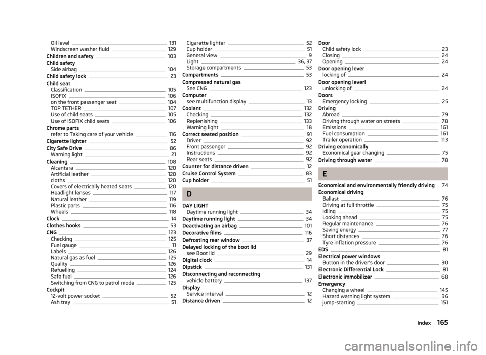
Oil level131
Windscreen washer fluid129
Children and safety103
Child safety Side airbag
104
Child safety lock23
Child seat Classification
105
ISOFIX106
on the front passenger seat104
TOP TETHER107
Use of child seats105
Use of ISOFIX child seats106
Chrome parts refer to Taking care of your vehicle
116
Cigarette lighter52
City Safe Drive86
Warning light21
Cleaning108
Alcantara120
Artificial leather120
cloths120
Covers of electrically heated seats120
Headlight lenses117
Natural leather119
Plastic parts116
Wheels118
Clock14
Clothes hooks53
CNG123
Checking125
Fuel gauge11
Labels126
Natural gas as fuel125
Quality126
Refuelling124
Safe fuel126
Switching from CNG to petrol mode125
Cockpit 12-volt power socket
52
Ash tray51
Cigarette lighter52
Cup holder51
General view9
Light36, 37
Storage compartments53
Compartments53
Compressed natural gas See CNG
123
Computer see multifunction display
13
Coolant132
Checking132
Replenishing133
Warning light18
Correct seated position91
Driver92
Front passenger92
Instructions92
Rear seats92
Counter for distance driven12
Cruise Control System83
Cup holder51
D
DAY LIGHT Daytime running light
34
Daytime running light34
Deactivating an airbag101
Decorative films116
Defrosting rear window37
Delayed locking of the boot lid see Boot lid
29
Digital clock14
Dipstick131
Disconnecting and reconnecting vehicle battery
137
Display Service interval
12
Distance driven12
Door Child safety lock23
Closing24
Opening24
Door opening lever locking of
24
Door opening leverl unlocking of
24
Doors Emergency locking
25
Driving Abroad
79
Driving through water on streets78
Emissions161
Fuel consumption161
Trailer operation113
Driving economically Economical gear changing
75
Driving through water78
E
Economical and environmentally friendly driving
74
Economical driving Ballast
76
Driving at full throttle75
Idling75
Looking ahead75
Regular maintenance76
Saving energy77
Short distances76
Tyre inflation pressure76
EDS81
Electrical power windows Button in the driver's door
30
Electronic Differential Lock81
Electronic immobilizer68
Emergency Changing a wheel
145
Hazard warning light system36
jump-starting151
165Index