warning light SKODA CITIGO 2014 1.G Service Manual
[x] Cancel search | Manufacturer: SKODA, Model Year: 2014, Model line: CITIGO, Model: SKODA CITIGO 2014 1.GPages: 164, PDF Size: 12.08 MB
Page 83 of 164
The gearshift indicator must be observed when changing gear » page 30.
Always depress the clutch pedal all the way down. This prevents uneven wear
to the clutch.
Reverse gear is engaged›
Stop the vehicle.
›
The clutch pedal is fully depressed.
›
Move the shift lever to the idle position switch and press down.
›
Move the shift lever fully to the right and then backwards in position R.
The reversing lights will come on once reverse gear is engaged, provided the
ignition is on.
WARNINGNever engage reverse gear when driving – risk of accident!
CAUTION
■ If not in the process of changing gear, do not leave your hand on the gear-
shift lever while driving. The pressure from the hand can cause the gearshift
mechanism to wear excessively.■
When stopping on a slope, never try to hold the vehicle in position by using
the accelerator pedal and the clutch – this may lead to clutch damage.
Pedals
The operation of the pedals must not be hindered under any circumstances!
In the driver's footwell, only a footmat, which is attached to the two corre-
sponding attachment points may be used.
Only use factory-supplied footmats or footmats from the range of ŠKODAOrigi-
nal Accessories, which are fitted to two attachment points.
WARNINGNo objects are allowed in the driver's footwell – risk of obstruction or limi-
tation in operating the pedals!Automated transmission
Introduction
This chapter contains information on the following subjects:
Modes and lever control
81
Manual gearshift (Tiptronic)
81
Starting-off and driving
82
The automatic transmission performs automatic gear changes.
The modes of the automatic transmission are adjusted by the driver by means
of the selector lever.
WARNING■ No throttle when it is set before starting the mode for moving forward
with the selector lever - there is a risk of accident!■
Never move the selector lever to mode R when driving – risk of accident!
■
Always firmly apply the handbrake before leaving the vehicle! Otherwise
the vehicle could then start to move and potentially cause an accident!
CAUTION
When stopping on a slope, never try to hold the vehicle using the accelerator
pedal – this may lead to gear damage.
Note
■ The engine can only be left on in position N, when the brake pedal is de-
pressed .■
If the selector lever position N is accidentally selected while driving, it is first
necessary to release pressure on the accelerator pedal and wait for the idling
speed of the engine to be reached before the selector lever can be engaged in
the drive position.
■
If the N symbol flashes next to the selector lever, engage the selector lever
position N.
80Driving
Page 84 of 164
Modes and lever controlFig. 81
Selector lever
Read and observe and on page 80 first.
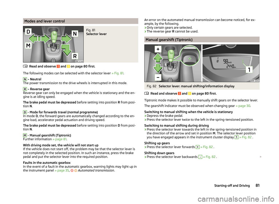
The following modes can be selected with the selector lever » Fig. 81.
N
– Neutral
The power transmission to the drive wheels is interrupted in this mode.
R
– Reverse gear
Reverse gear can only be engaged when the vehicle is stationary and the en-
gine is at idling speed.
The brake pedal must be depressed before setting into position R from posi-
tion N.
D
- Mode for forwards travel (normal programme)
In mode D, the forward gears are automatically changed according to the en-
gine load, accelerator pedal actuation and driving speed.
The brake pedal must be depressed before setting into position D from posi-
tion N.
M
- Manual gearshift (Tiptronic)
Further information » page 81.
With driving mode set, the vehicle will not start up
If the vehicle does not start off, the problem may be that the selector lever is
not completely in the selected position. In such an instance, press the brake
pedal and put the selector lever into the required position.
Faults in the automatic gearbox
In the event of a fault in the automatic gearbox, warning lights may light up in
the instrument panel » page 35,
Automated transmission
.
An error on the automated manual transmission can become noticed, for ex-
ample, by the following.
› Only certain gears are selected.
› The reverse gear
R cannot be used.
Manual gearshift (Tiptronic)
Fig. 82
Selector lever: manual shifting/information display
Read and observe
and on page 80 first.
Tiptronic mode makes it possible to manually shift gears on the selector lever. The gearshift indicator must be observed when changing gear » page 30.
Switching to manual shifting when the vehicle is stationary
›
Depress the brake pedal.
›
Press the selector lever twice to the left in the spring-tensioned position.
Switching to manual shifting during driving
›
Press the selector lever towards the left in the spring-tensioned position in
the direction of the arrow and set in position M. The selector lever position
you have engaged appears in the instrument cluster display
1
» Fig. 82 .
Shifting up gears
›
Press the selector lever forwards
+
» Fig. 82 .
Shifting down gears
›
Press the selector lever backwards
-
» Fig. 82 .
81Starting-off and Driving
Page 87 of 164
Driving off paved roadsRead and observe
on page 83 first.
Only drive on such roads and in such terrain, which match the vehicle parame-ters » page 143 , Technical data as well as your driving skills.
The driver is always responsible for deciding whether the vehicle can handle
travelling in the given terrain.
WARNINGDrive particularly aware and pro-actively outside paved roads.■Always adjust your driving to the current terrain and weather conditions.
Excessive speed or incorrect driving manoeuvres can cause damage to the
vehicle and lead to serious injuries.■
Objects trapped under the floor of the vehicle can damage the fuel lines,
the brake system, the seals and other parts of the chassis. Check the un-
derside of the vehicle and remove the trapped objects.
■
Combustible objects such as dry leaves or twigs caught under the base of
the vehicle could ignite on hot vehicle parts - risk of fire!
CAUTION
■ Pay attention to the ground clearance of the vehicle! When driving over ob-
jects which are larger than the ground clearance, the chassis and its compo-
nents can get damaged.■
Drive slowly in unknown terrain and watch out for unexpected obstacles,
such as potholes, rocks, stumps, etc.
■
Check up on confusing sections of unpaved roads before travelling on them
and consider whether such travelling is possible without risk.
Assist systems
Braking and stabilisation systems
Introduction
This chapter contains information on the following subjects:
Electronic Stability Control (ESC)
84
Antilock Braking System (ABS)
85
Traction Control System (TC)
85
Electronic Differential Lock (EDL)
85
Hydraulic Brake Assist (HBA)
85
Hill Hold Control (HHC)
85
This chapter deals with the functions of the braking and stabilisation systems,
with the error indicator referred to in chapter » page 33, Warning lights .
The braking and stabilisation systems are automatically activated each time the ignition is switched on.
WARNING■ A lack of fuel can cause irregular engine running or cause the engine to
shut down. The brake assist systems would then fail to function – risk of
accident!■
The increased safety provided by the brake assist systems must not
tempt you to take safety risks – risk of accident!
■
Adjust the speed and driving style to the current visibility, weather, road
and traffic conditions.
Electronic Stability Control (ESC)
Read and observe
on page 84 first.
The ESC improves vehicle stability in dynamic driving situations, such as whenthe vehicle starts to skid.
The ESC monitors whether the desired direction of the current vehicle motion
is occurring. In case of any deviation (e.g. oversteer), the ESC automatically
brakes individual wheels to maintain the desired direction.
During an intervention of the system, the warning light flashes in the instru-
ment cluster.
84Driving
Page 90 of 164
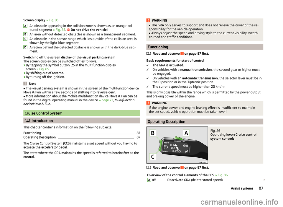
Screen display » Fig. 85
An obstacle appearing in the collision zone is shown as an orange-col-
oured segment » Fig. 85.
Do not drive the vehicle!
An area without detected obstacles is shown as a transparent segment.
An obstacle in the sensor range which lies outside of the collision area is
shown by the light-blue segment.
A region behind the detected obstacle is shown with the dark-blue seg-
ment.
Switching off the screen display of the visual parking system
The screen display can be switched off as follows.
› By tapping the symbol button
in the multifunction display
screen » Fig. 85 .
› By shifting out of reverse.
› By turning off the ignition.
Note
■
The visual parking system is shown in the screen of the multifunction device
Move & Fun within a few seconds of shifting into reverse gear.■
More information about the mobile multifunction device Move & Fun can be
found in the digital operating manual in the device » page 73, Multifunction
deviceMove & Fun .
Cruise Control System
Introduction
This chapter contains information on the following subjects:
Functioning
87
Operating Description
87
The Cruise Control System (CCS) maintains a set speed without you having to
actuate the accelerator pedal.
The state where the GRA maintains the speed is referred to hereinafter as the
control .
ABCDWARNING■
The GRA only serves to support and does not relieve the driver of the re-
sponsibility for the vehicle operation.■
Always adjust the speed and driving style to the current visibility, weath-
er, road and traffic conditions.
Functioning
Read and observe
on page 87 first.
Basic requirements for start of control The GRA is activated.
On vehicles with a manual transmission , the second gear or higher must
be engaged.
On vehicles with an automatic transmission , the selector lever must be in
the D position or in the Tiptronic position.
The current speed must be higher than 20 km/hr.
This is only possible within the range which is permitted by the power output and braking power of the engine.
WARNINGIf the engine power and engine braking effect is insufficient to maintain
the set speed, vehicle operation must be taken over!
Operating Description
Fig. 86
Operating lever: Cruise control
system controls
Read and observe on page 87 first.
Overview of the control elements of the CCS » Fig. 86ADeactivate GRA (delete stored speed) 87Assist systems
Page 91 of 164
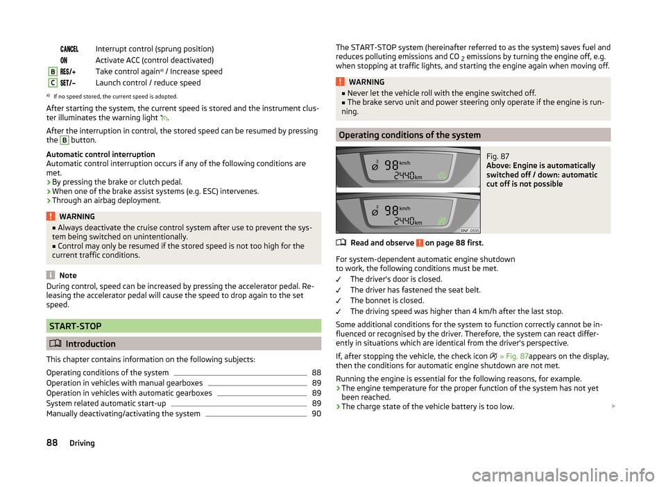
Interrupt control (sprung position) Activate ACC (control deactivated)BTake control againa)
/ Increase speedCLaunch control / reduce speeda)
If no speed stored, the current speed is adopted.
After starting the system, the current speed is stored and the instrument clus-
ter illuminates the warning light
.
After the interruption in control, the stored speed can be resumed by pressing
the
B
button.
Automatic control interruption
Automatic control interruption occurs if any of the following conditions are
met.
› By pressing the brake or clutch pedal.
› When one of the brake assist systems (e.g. ESC) intervenes.
› Through an airbag deployment.
WARNING■
Always deactivate the cruise control system after use to prevent the sys-
tem being switched on unintentionally.■
Control may only be resumed if the stored speed is not too high for the
current traffic conditions.
Note
During control, speed can be increased by pressing the accelerator pedal. Re-
leasing the accelerator pedal will cause the speed to drop again to the set
speed.
START-STOP
Introduction
This chapter contains information on the following subjects:
Operating conditions of the system
88
Operation in vehicles with manual gearboxes
89
Operation in vehicles with automatic gearboxes
89
System related automatic start-up
89
Manually deactivating/activating the system
90The START-STOP system (hereinafter referred to as the system) saves fuel and
reduces polluting emissions and CO 2 emissions by turning the engine off, e.g.
when stopping at traffic lights, and starting the engine again when moving off.WARNING■ Never let the vehicle roll with the engine switched off.■The brake servo unit and power steering only operate if the engine is run-
ning.
Operating conditions of the system
Fig. 87
Above: Engine is automatically
switched off / down: automatic
cut off is not possible
Read and observe on page 88 first.
For system-dependent automatic engine shutdown
to work, the following conditions must be met.
The driver's door is closed.
The driver has fastened the seat belt.
The bonnet is closed.
The driving speed was higher than 4 km/h after the last stop.
Some additional conditions for the system to function correctly cannot be in-
fluenced or recognised by the driver. Therefore, the system can react differ-
ently in situations which are identical from the driver's perspective.
If, after stopping the vehicle, the check icon
» Fig. 87 appears on the display,
then the conditions for automatic engine shutdown are not met.
Running the engine is essential for the following reasons, for example.
› The engine temperature for the proper function of the system has not yet
been reached.
› The charge state of the vehicle battery is too low.
88Driving
Page 93 of 164
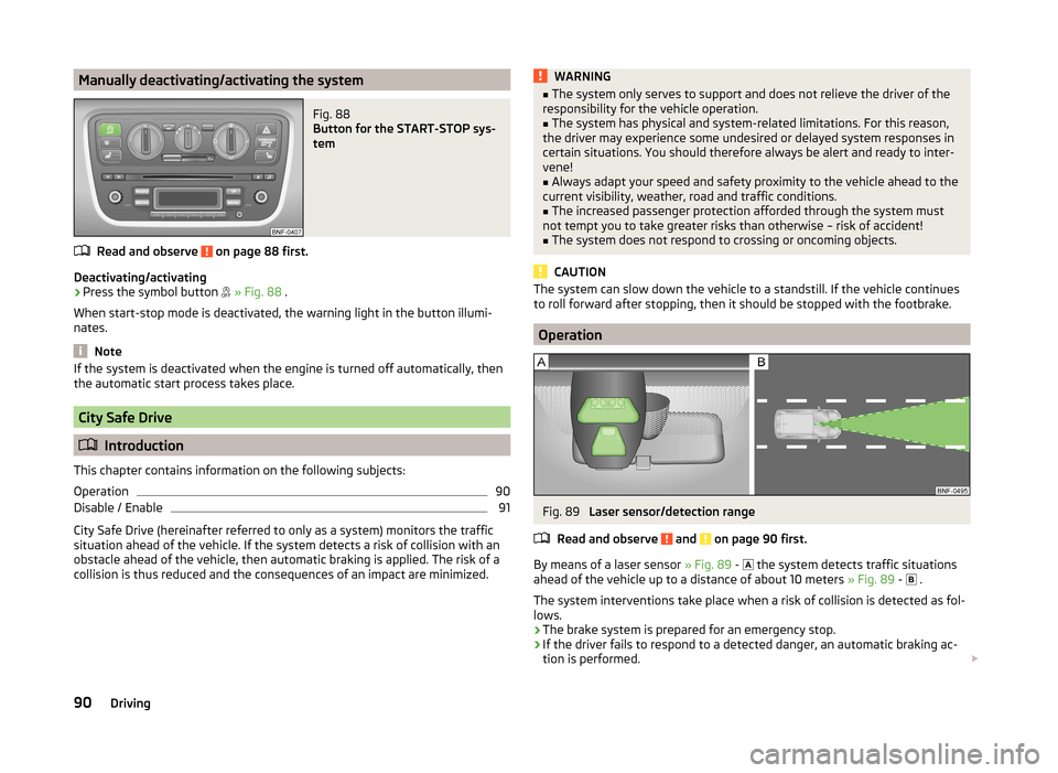
Manually deactivating/activating the systemFig. 88
Button for the START-STOP sys-
tem
Read and observe on page 88 first.
Deactivating/activating
›
Press the symbol button
» Fig. 88 .
When start-stop mode is deactivated, the warning light in the button illumi-
nates.
Note
If the system is deactivated when the engine is turned off automatically, then
the automatic start process takes place.
City Safe Drive
Introduction
This chapter contains information on the following subjects:
Operation
90
Disable / Enable
91
City Safe Drive (hereinafter referred to only as a system) monitors the traffic
situation ahead of the vehicle. If the system detects a risk of collision with an
obstacle ahead of the vehicle, then automatic braking is applied. The risk of a
collision is thus reduced and the consequences of an impact are minimized.
WARNING■ The system only serves to support and does not relieve the driver of the
responsibility for the vehicle operation.■
The system has physical and system-related limitations. For this reason,
the driver may experience some undesired or delayed system responses in
certain situations. You should therefore always be alert and ready to inter-
vene!
■
Always adapt your speed and safety proximity to the vehicle ahead to the
current visibility, weather, road and traffic conditions.
■
The increased passenger protection afforded through the system must
not tempt you to take greater risks than otherwise – risk of accident!
■
The system does not respond to crossing or oncoming objects.
CAUTION
The system can slow down the vehicle to a standstill. If the vehicle continues
to roll forward after stopping, then it should be stopped with the footbrake.
Operation
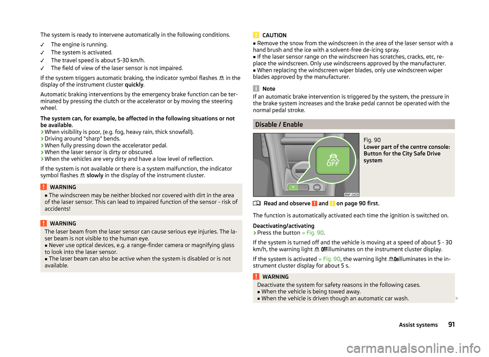
Fig. 89
Laser sensor/detection range
Read and observe
and on page 90 first.
By means of a laser sensor » Fig. 89 -
the system detects traffic situations
ahead of the vehicle up to a distance of about 10 meters » Fig. 89 -
.
The system interventions take place when a risk of collision is detected as fol- lows.
› The brake system is prepared for an emergency stop.
› If the driver fails to respond to a detected danger, an automatic braking ac-
tion is performed.
90Driving
Page 94 of 164
The system is ready to intervene automatically in the following conditions.The engine is running.
The system is activated.
The travel speed is about 5-30 km/h.
The field of view of the laser sensor is not impaired.
If the system triggers automatic braking, the indicator symbol flashes
in the
display of the instrument cluster quickly.
Automatic braking interventions by the emergency brake function can be ter-
minated by pressing the clutch or the accelerator or by moving the steering
wheel.
The system can, for example, be affected in the following situations or not
be available.
› When visibility is poor, (e.g. fog, heavy rain, thick snowfall).
› Driving around “sharp” bends.
› When fully pressing down the accelerator pedal.
› When the laser sensor is dirty or obscured.
› When the vehicles are very dirty and have a low level of reflection.
If the system is not available or there is a system malfunction, the indicator
symbol flashes
slowly in the display of the instrument cluster.WARNING■
The windscreen may be neither blocked nor covered with dirt in the area
of the laser sensor. This can lead to impaired function of the sensor - risk of
accidents!WARNINGThe laser beam from the laser sensor can cause serious eye injuries. The la-
ser beam is not visible to the human eye.■
Never use optical devices, e.g. a range-finder camera or magnifying glass
to look into the laser sensor.
■
The laser beam can also be active when the system is disabled or is not
available.
CAUTION■ Remove the snow from the windscreen in the area of the laser sensor with a
hand brush and the ice with a solvent-free de-icing spray.■
If the laser sensor range on the windscreen has scratches, cracks, etc, re-
place the windscreen. Only use windscreens approved by the manufacturer.
■
When replacing the windscreen wiper blades, only use windscreen wiper
blades approved by the manufacturer.
Note
If an automatic brake intervention is triggered by the system, the pressure in
the brake system increases and the brake pedal cannot be operated with the
normal pedal stroke.
Disable / Enable
Fig. 90
Lower part of the centre console:
Button for the City Safe Drive
system
Read and observe and on page 90 first.
The function is automatically activated each time the ignition is switched on.
Deactivating/activating
›
Press the button » Fig. 90.
If the system is turned off and the vehicle is moving at a speed of about 5 - 30
km/h, the warning light
illuminates on the instrument cluster display.
If the system is activated » Fig. 90, the warning light
illuminates in the in-
strument cluster display for about 5 s.
WARNINGDeactivate the system for safety reasons in the following cases.■When the vehicle is being towed away.■
When the vehicle is driven though an automatic car wash.
91Assist systems
Page 95 of 164
WARNING (Continued)■If the laser sensor is damaged or faulty.■When the vehicle is on a rolling test bench.■
When the windscreen is damaged in the region of the laser sensor.
■
For example, if the charge extends to the roof rack over the front edge of
the roof.
Tyre pressure monitoring
Introduction
This chapter contains information on the following subjects:
Save tyre pressure values
92
The tyre pressure monitoring function (hereinafter referred to only as a sys-
tem) monitors the tyre pressure while driving.
If the rolling circumference of a wheel is changed, the warning light in the
instrument cluster illuminates and an audible signal sounds.
Information on the procedure for the notification of change of tyre inflation
pressure » page 37 .
The system can only function properly if the tyres have the prescribed inflation
pressure and these pressure values are stored in the system.
WARNING■ Having the correct tyre inflation pressure is always the driver's responsi-
bility. Tyre pressure should be checked regularly » page 118.■
The system cannot warn in case of very rapid tyre inflation pressure loss,
e.g. in case of sudden tyre damage.
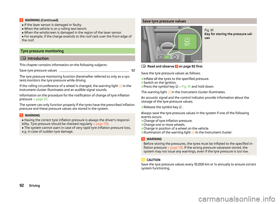
Save tyre pressure valuesFig. 91
Key for storing the pressure val-
ues
Read and observe on page 92 first.
Save the tyre pressure values as follows.
›
Inflate all the tyres to the specified pressure.
›
Switch on the ignition.
›
Press the symbol key
» Fig. 91 and hold down.
The warning light in the instrument cluster illuminates.
An acoustic signal and the control indicator provide information about the
storage of the tyre pressure values.
›
Release the symbol key .
Always save the tyre pressure values in the system if one of the following
events occurs.
› Change of tyre inflation pressure.
› Change one or more wheels.
› Change in position of a wheel on the vehicle.
› Illumination of the warning light
in the instrument cluster.
WARNINGBefore storing the pressures, the tyres must be inflated to the specified in-
flation pressure » page 118. If the wrong pressure valuesare stored, the
system may not issue any warnings, even if the tyre pressure is too low.
CAUTION
Save the tyre pressure values every 10,000 km or 1x annually to ensure correct
system functioning.92Driving
Page 100 of 164
Washing by handRead and observe
and on page 96 first.
Soak the dirt with plenty of water and rinse as well as possible.
Clean the vehicle with a soft sponge, a washing glove or a washing brush.
Work from the top to the bottom – starting with the roof.
For stubborn dirt, agents specifically intended for this purpose are to be used. Wash out the sponge or washing glove thoroughly at short intervals.
Clean wheels, door sills and similar parts last. Use a second sponge for such areas.
Give the vehicle a good rinse after washing it and dry it off using a chamois
leather.
WARNINGProtect your hands and arms from sharp-edged metal parts when cleaning
the underfloor or the inside of the wheel housings or the wheel trims – risk
of cuts!
CAUTION
■ Only apply slight pressure when cleaning the vehicle's paintwork.■Do not wash your vehicle in bright sunlight – risk of paint damage.
Automatic car wash systems
Read and observe
and on page 96 first.
The usual precautionary measures must be taken before washing the vehicle
in an automatic car wash system (e.g. closing the windows and the sliding/tilt-
ing roof etc.).
If your vehicle is fitted with any particular attached parts, such as a spoiler,
roof rack system, two-way radio aerial etc., it is best to consult the operator of
the car wash system beforehand.
After an automatic wash with wax treatment, the lips of the wipers should be
cleaned with cleaning agents specially designed for the purpose, and then de-
greased.
CAUTIONFold in the exterior mirrors to prevent damage before washing the vehicle in
an automatic car wash system. Never manually fold in electric exterior mirrors -
always use the electric controls.
Washing with a high-pressure cleaner
Read and observe
and on page 96 first.
When washing the vehicle with a high-pressure cleaner, the instructions foruse of the equipment must be observed. This applies in particular to the pres-
sure used and to the spraying distance .
Maintain a sufficiently large distance to the parking aid sensors and soft mate-
rials such as rubber hoses or insulation material.
CAUTION
■ If washing the vehicle in the winter using a hose or high-pressure cleaner,
ensure that the jet of water is not aimed directly at the locking cylinders or the
door/panel joints – risk of freezing!■
To avoid damaging the parking aid sensors while cleaning with high-pressure
cleaners or steam jets, the sensors must only be directly sprayed for short pe-
riods while a minimum distance of 10 cm must be observed.
Note
See also Washing cars with decorative films using a high-pressure clean-
er » page 99 .
Cleaning vehicle exterior
Introduction
This chapter contains information on the following subjects:
Vehicle paint work
98
Plastic parts
98
Rubber seals
98
Chrome parts
99
Decorative films
99
Windows and external mirrors
99
Headlight glasses
99
Door closing cylinder
100
97Care and maintenance
Page 103 of 164
CAUTION■The headlights are never to be wiped dry - there is a risk of damaging the
protective lacquer and the headlight glass subsequently developing cracks.■
Do not use sharp objects to clean the glasses - there is a risk of damaging
the protective lacquer and the headlight glasses subsequently developing
cracks.
■
Do not use any aggressive cleaning or chemical solvent products to clean the
headlights – risk of damaging the headlight lenses.
Door closing cylinder
Read and observe
and on page 98 first.
Specific products must be used for de-icing door lock cylinders.
CAUTION
Make sure that as little water as possible gets into the locking cylinder when
washing the vehicle - there is a risk of freezing the lock cylinder!
Cavity protection
Read and observe
and on page 98 first.
All the cavities of your vehicle which are at risk from corrosion are protected
for life by a layer of protective wax applied in the factory.
This wax protection does not need to be inspected or re-applied.
If any small amount of wax flow out of the cavities at high temperatures, these
must be removed with a plastic scraper and the stains cleaned using a petrole-
um cleaner.
WARNINGSafety regulations should be observed when using petroleum cleaner to re-
move wax – risk of fire!
Jack
Read and observe
and on page 98 first.
The jack is maintenance-free.
If necessary, the moving parts of the jack should be lubricated with a suitable
lubricant.
Wheels
Read and observe
and on page 98 first.
Wheel rims
Also thoroughly wash the wheel rims when washing the vehicle on a regular
basis.
Regularly remove salt and brake abrasion, otherwise the rim material will be
corroded.
Light alloy wheels
After washing thoroughly and treat the wheel rims with a protective product
for light alloy wheels.
For the treatment of wheel rims do not use products which may cause damage
to the paint on the rims.
CAUTION
■ Damage to the paint layer on the wheel rims must be touched up immediate-
ly.■
Severe layers of dirt on the wheels can also result in wheel imbalance. This
may show itself in the form of a wheel vibration which is transmitted to the
steering wheel which, in certain circumstances, can cause premature wear of
the steering. This means it is necessary to remove the dirt.
Under-body protection
Read and observe
and on page 98 first.
The underside of your vehicle is already permanently protected by the factory
against chemical and mechanical influences.
When driving, it cannot be guaranteed that no damage to the protective layer
will occur.
We recommend having the protective layer underneath the vehicle and the
chassis checked — preferably before the beginning of winter and at the end of
winter.
WARNINGNever use additional underbody protection or anti-corrosion agents for ex-
haust pipes, catalytic converters or heat shields. When the engine reaches
its operating temperature, these substances may ignite - risk of fire!100General Maintenance