engine SKODA CITIGO 2014 1.G Owner's Manual
[x] Cancel search | Manufacturer: SKODA, Model Year: 2014, Model line: CITIGO, Model: SKODA CITIGO 2014 1.GPages: 164, PDF Size: 12.08 MB
Page 5 of 164
Table of Contents
Board literature4
Notes
5
Structure and more information about the
Owner's Manual
6
Abbreviations
Safety
Passive Safety
8
General information
8
Correct and safe seated position
9
Seat belts
11
Using seat belts
11
Inertia reels and belt tensioners
14
Airbag system
15
Description of the airbag system
15
Airbag overview
16
Deactivating airbags
18
Transporting children safely
19
Child seat
19
Fastening systems
22
Using the system
Cockpit
27
Overview
26
Instruments and control lights
28
Instrument cluster
28
Multi-function display (MFD)
30
Warning lights
33
Unlocking and opening
39
Unlocking and locking
39
Luggage compartment lid
43Electric Windows44Mechanical windows45
Panorama sliding/tilting roof
46
Lights and visibility
48
Lights
48
Indoor Lighting
51
Visibility
52
Windscreen wipers and washers
52
Rear mirror
54
Seats and head restraints
55
Seats and head restraints
55
Seat features
57
Transporting and practical equipment
60
Useful equipment
60
Luggage compartment
65
Roof rack
68
Heating and air conditioning
70
Heating, ventilation, cooling
70
Communication and multimedia
73
Telephone and Move & Fun
73
Driving
Starting-off and Driving
76
Starting and turning off the engine
76
Brakes and parking
77
Manual gear changing and pedals
79
Automated transmission
80
Running in and economical driving
82
Driving through water and driving off of
made-up roads
83
Assist systems
84
Braking and stabilisation systems
84
Parking aid
85
Cruise Control System
87
START-STOP
88City Safe Drive90Tyre pressure monitoring92
General Maintenance
Care and maintenance
93
Modifications, adjustments and technical alterations
93
Washing vehicle
96
Cleaning vehicle exterior
97
Interior care
101
Inspecting and replenishing
103
Fuel
103
Engine compartment
107
Engine oil
110
Coolant
111
Brake fluid
113
Vehicle battery
113
Wheels
117
Tyres and wheel rims
117
Approved tyre / rim combinations
120
Winter operation
121
Do-it-yourself
Emergency equipment and self-help
122
Emergency equipment
122
Reserve and temporary spare
123
Changing a wheel
124
Puncture repair kit
127
Jump-starting
130
Towing the vehicle
131
Remote control
132
Emergency unlocking/locking
133
Replacing windscreen wiper blades
134
Fuses and light bulbs
135
Fuses
135
Replacing bulbs
1382Table of Contents
Page 10 of 164
AbbreviationsAbbreviationDefinitionrpmEngine revolutions per minuteABSAnti-lock brake systemAGMVehicle battery typeASGAutomatic gearboxCNGcompressed natural gasCO2Carbon dioxideEDLElectronic differential lockECEEconomic Commission for EuropeEPCEngine performance checkESCElectronic Stability ControlDRim depthEUEuropean UnionG-TECEngine designation at driven by compressed natural gas ve-
hiclesHBAHydraulic brake assistHHCUphill start assistkWKilowatt, measuring unit for the engine outputMGManual gearboxMFDMultifunction displayMPIGasoline engine with a multi-point fuel injectionN1Panel van intended exclusively or mainly for the transporta-
tion of goodsNmNewton meter, measuring unit for the engine torqueOPSvisual parking systemTCSTraction controlTMCService for transmitting traffic information to the driverVINVehicle identification number7Abbreviations
Page 11 of 164
Safety
Passive Safety
General information
Introduction
This chapter contains information on the following subjects:
Before setting off
8
Driving safety
8
Safety equipment
8
In this section you will find important information, tips and notes on the sub-
ject of passive safety in your vehicle.
We have combined everything here which you should be familiar with, for ex-
ample, regarding seat belts, airbags, child seats and safety of children.
WARNING■ This chapter contains important information on how to use the vehicle for
the driver and his occupants.■
You can find further information on safety concerning you and those trav-
elling with you in the following chapters of this owner's manual.
■
The complete on-board literature should always be in the vehicle. This
applies in particular, if you rent out or sell the vehicle.
Before setting off
Read and observe
on page 8 first.
For your own safety and the safety of the people travelling with you, please
pay attention to the following points before setting off.
Ensure that the lighting and the turn signal system are functioning proper-
ly.
Ensure that the function of the wipers and the condition of the wiper
blades are free of any defects.
Ensure that all of the windows offer good visibility to the outside.
Adjust the rear-view mirror so that vision to the rear is guaranteed.
Ensure that the mirrors are not covered.
Check the tyre inflation pressure.
Check the engine oil, brake fluid and coolant level.
Secure all items of luggage.
Do not exceed the permissible axle loads and permissible gross weight of
the vehicle.
Close all doors as well as the bonnet and boot lid.
Ensure that no objects can obstruct the pedals.
Protect children in suitable child seats with correctly fastened seat
belts » page 19 , Transporting children safely .
Adopt the correct seated position » page 9, Correct and safe seated
position . Tell your passengers to assume the correct seated position.
Driving safety
Read and observe
on page 8 first.
The driver is fully responsible for himself and his occupants. If your driving
safety is effected, you place yourself and the oncoming traffic at risk.
The following guidelines must therefore be observed. Do not become distracted from concentrating on the traffic situation, e.g.
by your passengers or mobile phone calls.
Never drive when your driving ability is impaired, e.g. due to medication, al-
cohol or drugs.
Keep to the traffic regulations and the permissible speed limit.
Always adjust the driving speed to the road, traffic and weather condi-
tions.
Take regular breaks on long journeys – at least every two hours.
Safety equipment
Read and observe
on page 8 first.
The following list contains only part of the safety equipment in your vehicle.
› Three-point seat belts for all the seats.
› Belt force limiters for the front seats.
› Belt tensioners for the front seats.
› Front airbag for the driver and the front passenger.
› Head, thorax, driver and front seat passenger side airbag with head restraint
function;
8Safety
Page 19 of 164
Deployment factors
It is not possible to generally determine which deployment conditions apply to
the airbag system in every situation. An important role is played by factors
such as the type of object that the vehicle hits (hard/soft), the impact angle,
vehicle speed etc.
A decisive factor for the deployment of the airbags is the deceleration which
occurs. The control unit analyses the nature of the collision and activates the
relevant restraint system.
If the vehicle deceleration which occurs and is measured during the collision
remains below the prescribed reference values specified in the control unit,
the airbags are not deployed although the vehicle may well suffer severe dam-
age to the bodywork as a consequence of the accident.
The following airbags will be deployed in the event of a severe frontal
collision.
› Driver’s front airbag.
› Front passenger airbag.
The following airbags will be deployed in the event of a severe side collision.
› Head-Thorax side airbag on the crash side.
When an airbag is deployed, the following events occur.
› The interior lighting illuminates (if the switch for the interior light is in the
door contact position).
› The hazard warning lights are switched on.
› All doors are unlocked.
› The fuel supply to the engine is interrupted.
Airbag overview
Introduction
This chapter contains information on the following subjects:
Front airbags
16
Side airbags Head-Thorax
17Front airbagsFig. 7
Driver airbag in the steering wheel/front passenger airbag in the
dashboard
Fig. 8
Safe distance to steering wheel/gas-filled airbags
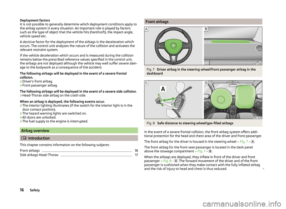
In the event of a severe frontal collision, the front airbag system offers addi-
tional protection for the head and chest area of the driver and front passenger.
The front airbag for the driver is housed in the steering wheel » Fig. 7 –
.
The front airbag for the front seat passenger is located in the dash panel
above the stowage compartment » Fig. 7 –
.
When the airbags are deployed, they inflate in front of the driver and front
passenger » Fig. 8 -
. The forward movement of the driver and of the front
passenger is cushioned when they make contact with the fully inflated airbag
and the risk of injury to head and chest is thus reduced.
16Safety
Page 31 of 164
Instruments and control lights
Instrument cluster
Introduction
This chapter contains information on the following subjects:
Overview
28
Speedometer
28
Fuel reserve display
29
Tachometer
29
Counter for distance driven
30
Service interval display
30
Gear recommendation
30
The instrument cluster gives the driver basic information such as the current
speed, engine speed, the state of some vehicle systems and the like.
WARNINGConcentrate fully at all times on your driving! As the driver you are fully re-
sponsible for road safety.
Overview
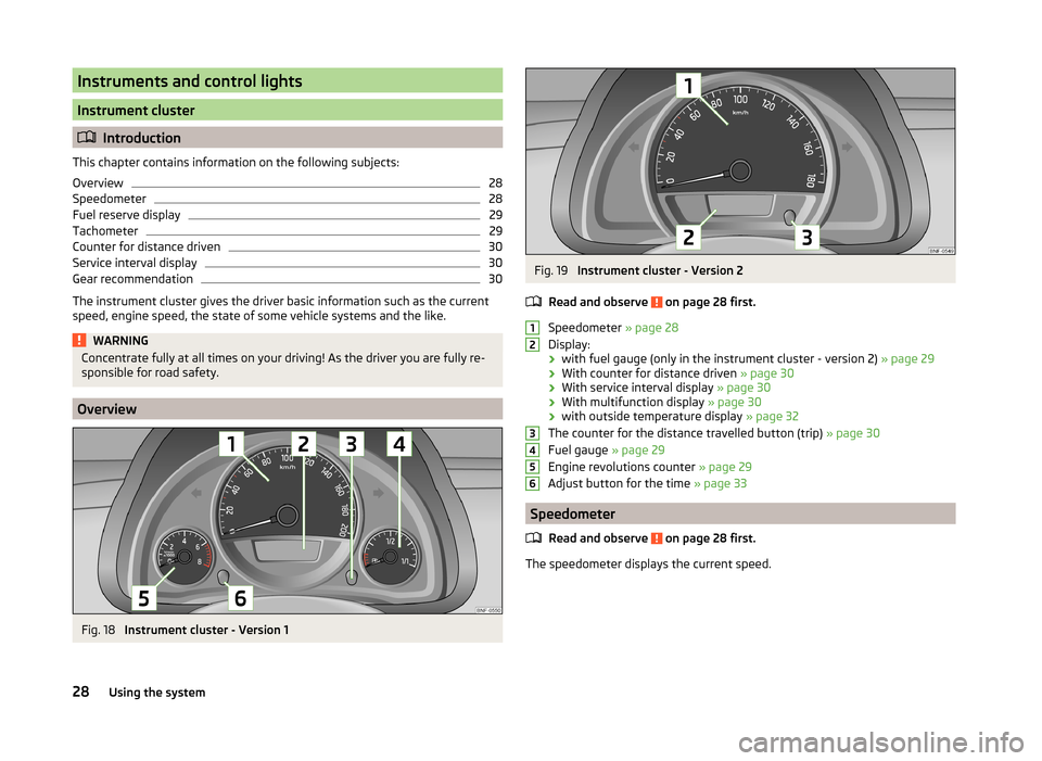
Fig. 18
Instrument cluster - Version 1
Fig. 19
Instrument cluster - Version 2
Read and observe
on page 28 first.
Speedometer » page 28
Display:
› with fuel gauge (only in the instrument cluster - version 2)
» page 29
› With counter for distance driven
» page 30
› With service interval display
» page 30
› With multifunction display
» page 30
› with outside temperature display
» page 32
The counter for the distance travelled button (trip) » page 30
Fuel gauge » page 29
Engine revolutions counter » page 29
Adjust button for the time » page 33
Speedometer
Read and observe
on page 28 first.
The speedometer displays the current speed.
12345628Using the system
Page 32 of 164
Fuel reserve displayFig. 20
Petrol fuel gauge: Version 1/version 2
Fig. 21
Gas gauge
Read and observe on page 28 first.
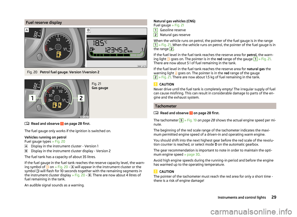
The fuel gauge only works if the ignition is switched on.
Vehicles running on petrol
Fuel gauge types » Fig. 20
Display in the instrument cluster - Version 1
Display in the instrument cluster display - Version 2
The fuel tank has a capacity of about 35 litres.
If the fuel gauge in the fuel tank reaches the reserve capacity level, the warn-
ing symbol of on
» Fig. 20 -
will appear in the instrument cluster or the
symbol will flash for 10 seconds together with the remaining segments in
the instrument cluster display » Fig. 20 -
. There are now about 4 litres of
fuel remaining in the tank.
An audible signal sounds as a warning.
Natural gas vehicles (CNG)
Fuel gauge » Fig. 21
Gasoline reserve
Natural gas reserve
When the vehicle runs on petrol, the pointer of the fuel gauge is in the range1
» Fig. 21 . When the vehicle runs on petrol, the pointer of the fuel gauge is in
the range
2
.
If the fuel level in the fuel tank reaches the reserve area for petrol, the warn-
ing light
goes on. The pointer is in the red range of the gauge
1
» Fig. 21 .
There are now about 5 l of fuel remaining in the tank.
If the fuel level in the fuel tank reaches the reserve area for natural gas the
warning light goes on. The pointer is in the
red range of the gauge
2
» Fig. 21 . There are now about 1.5 kg of fuel remaining in the tank.
CAUTION
Never drive until the fuel tank is completely empty! The irregular supply of fuel
can cause misfiring. This can result in considerable damage to parts of the en-
gine and the exhaust system.
Tachometer
Read and observe
on page 28 first.
The tachometer
5
» Fig. 19 on page 28 shows the actual engine speed per mi-
nute.
The beginning of the red scale range of the tachometer indicates the maxi-
mum permitted engine speed of a driven-in and operating warm engine.
You should shift into the next highest gear before the red scale of the revolu-
tion counter is reached, or select mode D on the automatic gearbox.
The gear recommendation is important to note in order to maintain the opti-
mum engine speed » page 30.
Avoid high engine speeds during the running-in period and before the engine
has warmed up to the operating temperature.
CAUTION
The pointer of the tachometer must reach the red area for only a short time -
there is a risk of engine damage!1229Instruments and control lights
Page 33 of 164
Counter for distance drivenRead and observe
on page 28 first.
To toggle between the odometer and the counter for the distance travelled(trip), briefly press the button
3
» Fig. 18 on page 28 or » Fig. 19 on page 28 .
Counter for distance travelled (trip)
The daily trip counter shows the distance driven since the time the counter
was last reset - in steps of 0.1 km.
Reset counter for distance travelled (trip)
›
Press and hold the
3
» Fig. 18 on page 28 or » Fig. 19 on page 28 button.
Odometer
The odometer indicates the total distance which the vehicle has been driven.
Service interval display
Read and observe
on page 28 first.
The service interval display shows the mileage to the next service event.
Before the next service interval has been reached, the message
appears in
the instrument cluster display for some seconds and the remaining kilometres
are shown after switching on the ignition.
If the time of the service has been reached, an acoustic signal will sound and the message
appears for a few seconds after switching on the ignition.
The information regarding the service intervals can be found in the service
schedule.
Note
Information is retained in the Service Interval Display even after the vehicle
battery is disconnected.
Gear recommendation
Read and observe
on page 28 first.
An information for the engaged gear is shown in the display of the instrument
cluster.
The function of the gear recommendation is to help reduce fuel consumption.
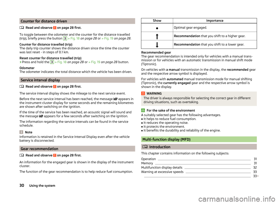
ShowImportanceOptimal gear engaged.Recommendation that you shift to a higher gear.Recommendation that you shift to a lower gear.
Recommended gear
The gear recommendation is intended only for vehicles with a manual trans-
mission or for vehicles with an automatic transmission in manual shift mode
(Tiptronic).
On vehicles with a manual transmission in the display, the recommended gear
and the respective arrow symbol is displayed.
For vehicles with automated manual transmission mode for manual shifting
(Tiptronic), the currently engaged gear and the respective arrow symbol is
shown in the display.
WARNINGThe driver is always responsible for selecting the correct gear in different
driving situations, such as overtaking.
For the sake of the environment
A suitably selected gear has the following advantages.■It helps to reduce fuel consumption.■
It reduces the operating noise.
■
It protects the environment.
■
It benefits the durability and reliability of the engine.
Multi-function display (MFD)
Introduction
This chapter contains information on the following subjects:
Operation
31
Memory
31
Multifunction display details
32
Warning at excessive speeds
33
33
30Using the system
Page 36 of 164
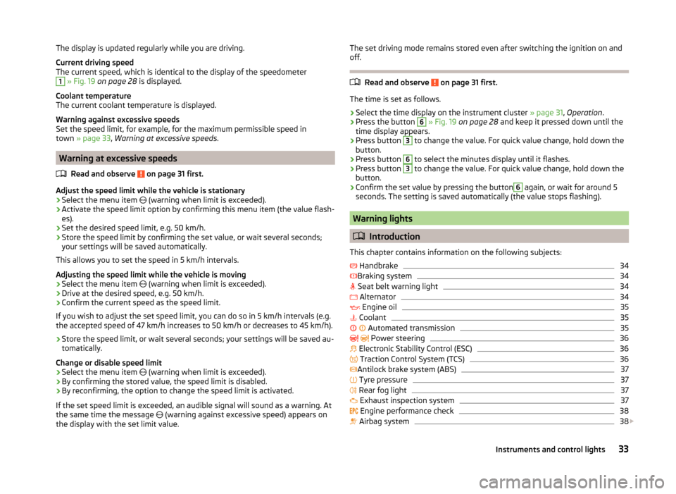
The display is updated regularly while you are driving.
Current driving speed
The current speed, which is identical to the display of the speedometer1
» Fig. 19 on page 28 is displayed.
Coolant temperature
The current coolant temperature is displayed.
Warning against excessive speeds
Set the speed limit, for example, for the maximum permissible speed in
town » page 33 , Warning at excessive speeds .
Warning at excessive speeds
Read and observe
on page 31 first.
Adjust the speed limit while the vehicle is stationary
›
Select the menu item (warning when limit is exceeded).
›
Activate the speed limit option by confirming this menu item (the value flash-
es).
›
Set the desired speed limit, e.g. 50 km/h.
›
Store the speed limit by confirming the set value, or wait several seconds;
your settings will be saved automatically.
This allows you to set the speed in 5 km/h intervals.
Adjusting the speed limit while the vehicle is moving
›
Select the menu item (warning when limit is exceeded).
›
Drive at the desired speed, e.g. 50 km/h.
›
Confirm the current speed as the speed limit.
If you wish to adjust the set speed limit, you can do so in 5 km/h intervals (e.g.
the accepted speed of 47 km/h increases to 50 km/h or decreases to 45 km/h).
›
Store the speed limit, or wait several seconds; your settings will be saved au-
tomatically.
Change or disable speed limit
›
Select the menu item (warning when limit is exceeded).
›
By confirming the stored value, the speed limit is disabled.
›
By reconfirming, the option to change the speed limit is activated.
If the set speed limit is exceeded, an audible signal will sound as a warning. At
the same time the message (warning against excessive speed) appears on
the display with the set limit value.
The set driving mode remains stored even after switching the ignition on and
off.
Read and observe on page 31 first.
The time is set as follows.
›
Select the time display on the instrument cluster » page 31, Operation .
›
Press the button
6
» Fig. 19 on page 28 and keep it pressed down until the
time display appears.
›
Press button
3
to change the value. For quick value change, hold down the
button.
›
Press button
6
to select the minutes display until it flashes.
›
Press button
3
to change the value. For quick value change, hold down the
button.
›
Confirm the set value by pressing the button
6
again, or wait for around 5
seconds. The setting is saved automatically (the value stops flashing).
Warning lights
Introduction
This chapter contains information on the following subjects:
Handbrake
34
Braking system
34
Seat belt warning light
34
Alternator
34
Engine oil
35
Coolant
35
Automated transmission
35
Power steering
36
Electronic Stability Control (ESC)
36
Traction Control System (TCS)
36
Antilock brake system (ABS)
37
Tyre pressure
37
Rear fog light
37
Exhaust inspection system
37
Engine performance check
38
Airbag system
38
33Instruments and control lights
Page 37 of 164
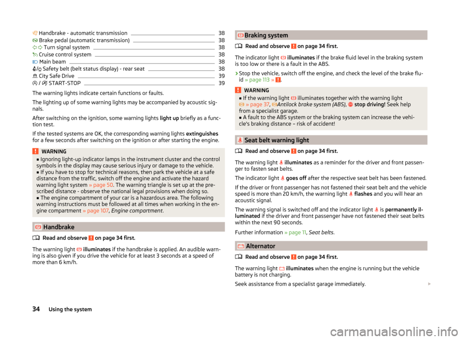
Handbrake - automatic transmission38 Brake pedal (automatic transmission)38
Turn signal system
38
Cruise control system
38
Main beam
38
/ Safety belt (belt status display) - rear seat
38
City Safe Drive
39
/
START-STOP
39
The warning lights indicate certain functions or faults.
The lighting up of some warning lights may be accompanied by acoustic sig-
nals.
After switching on the ignition, some warning lights light up briefly as a func-
tion test.
If the tested systems are OK, the corresponding warning lights extinguishes
for a few seconds after switching on the ignition or after starting the engine.
WARNING■ Ignoring light-up indicator lamps in the instrument cluster and the control
symbols in the display may cause serious injury or damage to the vehicle.■
If you have to stop for technical reasons, then park the vehicle at a safe
distance from the traffic, switch off the engine and activate the hazard
warning light system » page 50. The warning triangle is set up at the pre-
scribed distance - observe the national legal provisions when doing so.
■
The engine compartment of your car is a hazardous area. The following
warning instructions must be followed at all times when working in the en-
gine compartment » page 107, Engine compartment .
Handbrake
Read and observe
on page 34 first.
The warning light
illuminates if the handbrake is applied. An audible warn-
ing is also given if you drive the vehicle for at least 3 seconds at a speed of
more than 6 km/h.
Braking system
Read and observe
on page 34 first.
The indicator light
illuminates if the brake fluid level in the braking system
is too low or there is a fault in the ABS.
›
Stop the vehicle, switch off the engine, and check the level of the brake flu-
id » page 113 » .
WARNING■
If the warning light illuminates together with the warning light
» page 37 , Antilock brake system (ABS) , stop driving! Seek help
from a specialist garage.■
A fault to the ABS system or the braking system can increase the vehi-
cle's braking distance – risk of accident!
Seat belt warning light
Read and observe
on page 34 first.
The warning light
illuminates as a reminder for the driver and front passen-
ger to fasten seat belts.
The indicator light
goes off after the respective seat belt has been fastened.
If the driver or front passenger has not fastened their seat belt and the vehicle
speed is more than 20 km/h, the warning light
flashes and you will hear an
acoustic signal.
The warning signal is switched off and the indicator light is
permanently il-
luminated if the driver and front passenger have not fastened their seat belts
within the next 90 seconds.
Further information » page 11, Seat belts .
Alternator
Read and observe
on page 34 first.
The warning light
illuminates when the engine is running but the vehicle
battery is not charging.
Seek assistance from a specialist garage immediately.
34Using the system
Page 38 of 164
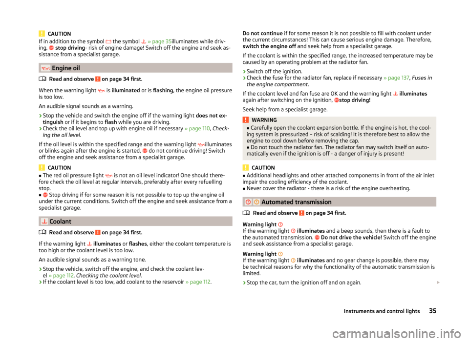
CAUTIONIf in addition to the symbol the symbol » page 35 illuminates while driv-
ing, stop driving - risk of engine damage! Switch off the engine and seek as-
sistance from a specialist garage.
Engine oil
Read and observe
on page 34 first.
When the warning light is
illuminated or is flashing , the engine oil pressure
is too low.
An audible signal sounds as a warning.
›
Stop the vehicle and switch the engine off if the warning light does not ex-
tinguish or if it begins to flash while you are driving.
›
Check the oil level and top up with engine oil if necessary
» page 110, Check-
ing the oil level .
If the oil level is within the specified range and the warning light illuminates
or blinks again after the engine is started, do not continue driving! Switch
off the engine and seek assistance from a specialist garage.
CAUTION
■ The red oil pressure light is not an oil level indicator! One should there-
fore check the oil level at regular intervals, preferably after every refuelling
stop.■
Stop driving if for some reason it is not possible to top up the engine oil
under the current conditions. Switch off the engine and seek assistance from a
specialist garage.
Coolant
Read and observe
on page 34 first.
If the warning light
illuminates or flashes , either the coolant temperature is
too high or the coolant level is too low.
An audible signal sounds as a warning tone.
›
Stop the vehicle, switch off the engine, and check the coolant lev-
el » page 112 , Checking the coolant level .
›
If the coolant level is too low, add coolant to the reservoir » page 112.
Do not continue if for some reason it is not possible to fill with coolant under
the current circumstances! This can cause serious engine damage. Therefore,
switch the engine off and seek help from a specialist garage.
If the coolant is within the specified range, the increased temperature may be
caused by an operating problem at the radiator fan.›
Switch off the ignition.
›
Check the fuse for the radiator fan, replace if necessary » page 137, Fuses in
the engine compartment .
If the coolant level and fan fuse are OK and the warning light
illuminates
again after switching on the ignition,
stop driving!
Seek help from a specialist garage.
WARNING■ Carefully open the coolant expansion bottle. If the engine is hot, the cool-
ing system is pressurized – risk of scalding! It is therefore best to allow the
engine to cool down before removing the cap.■
Do not touch the radiator fan. The radiator fan may switch itself on auto-
matically even if the ignition is off - a danger of injury is present!
CAUTION
■ Additional headlights and other attached components in front of the air inlet
impair the cooling efficiency of the coolant.■
Never cover the radiator - there is a risk of the engine overheating.
Automated transmission
Read and observe
on page 34 first.
Warning light
If the warning light
illuminates and a beep sounds, then there is a fault to
the automated transmission.
Do not drive the vehicle! Switch off the engine
and seek assistance from a specialist garage.
Warning light
If the warning light
illuminates and no gear change is possible, there may
be technical reasons for why the functionality of the automatic transmission is
limited.
›
Stop the car, turn the ignition off and on again.
35Instruments and control lights