clutch SKODA CITIGO 2015 1.G Owner's Manual
[x] Cancel search | Manufacturer: SKODA, Model Year: 2015, Model line: CITIGO, Model: SKODA CITIGO 2015 1.GPages: 160, PDF Size: 23.1 MB
Page 11 of 160
WARNING■The front seats and all head restraints must be adjusted to match the
body size at all times and the seat belt must always be fastened properly to
provide the most effective levels of protection to the passengers.■
Each occupant must correctly fasten the seat belt belonging to the seat.
Children must be fastened » page 19, Transporting children safely with a
suitable restraint system.
■
By sitting incorrectly, the occupant is risking life-threatening injuries.
■
The seat backrests must not be tilted too far back when driving, as this
will impair the function of the seat belts and of the airbag system – risk of
injury!
Correct seat position of the driver
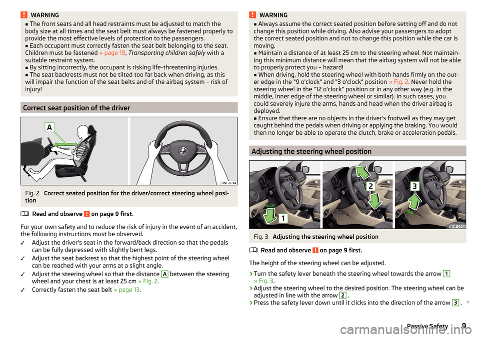
Fig. 2
Correct seated position for the driver/correct steering wheel posi-
tion
Read and observe
on page 9 first.
For your own safety and to reduce the risk of injury in the event of an accident,
the following instructions must be observed.
Adjust the driver’s seat in the forward/back direction so that the pedals
can be fully depressed with slightly bent legs.
Adjust the seat backrest so that the highest point of the steering wheel
can be reached with your arms at a slight angle.
Adjust the steering wheel so that the distance
A
between the steering
wheel and your chest is at least 25 cm » Fig. 2.
Correctly fasten the seat belt » page 13.
WARNING■
Always assume the correct seated position before setting off and do not
change this position while driving. Also advise your passengers to adopt
the correct seated position and not to change this position while the car is
moving.■
Maintain a distance of at least 25 cm to the steering wheel. Not maintain-
ing this minimum distance will mean that the airbag system will not be able
to properly protect you – hazard!
■
When driving, hold the steering wheel with both hands firmly on the out-
er edge in the “9 o'clock” and “3 o'clock” position » Fig. 2. Never hold the
steering wheel in the “12 o'clock” position or in any other way (e.g. in the
middle, inner edge of the steering wheel or similar). In such cases, you
could severely injure the arms, hands and head when the driver airbag is
deployed.
■
Ensure that there are no objects in the driver's footwell as they may get
caught behind the pedals when driving or applying the braking. You would
then no longer be able to operate the clutch, brake or acceleration pedals.
Adjusting the steering wheel position
Fig. 3
Adjusting the steering wheel position
Read and observe
on page 9 first.
The height of the steering wheel can be adjusted.
›
Turn the safety lever beneath the steering wheel towards the arrow
1
» Fig. 3 .
›
Adjust the steering wheel to the desired position. The steering wheel can be
adjusted in line with the arrow
2
.
›
Press the safety lever down until it clicks into the direction of the arrow
3
.
9Passive Safety
Page 60 of 160
Transporting and practical equipment
Useful equipment
Introduction
This chapter contains information on the following subjects:
Car park ticket holder
58
Storage compartment on the driver's side
58
Storage compartments in the front centre console
59
Cup holders
59
Waste container
59
Cigarette lighter
60
Ashtray
61
12-Volt power outlet
61
Multimedia holder
62
Photo holder
62
Storage compartment on the front passenger side - version 1
62
Storage compartment on the passenger side - version 2
62
Foldable hook
63
Clothes hook
63
Net pockets on the front seat rest
64
Stowage compartments in front of the rear seats
64WARNING■ Do not place anything on the dash panel. These objects might slide or fall
down when driving (when accelerating, cornering or following a bad ma-
noeuvre) and may distract you from concentrating on the traffic – there is a
risk of an accident.■
When driving, ensure that no objects from the centre console or from oth-
er storage compartments can get into the driver's footwell. You would not
be able to brake, operate the clutch pedal or accelerate - danger of causing
an accident!
■
No objects should be placed in the storage compartments nor in the
drinks holders; the vehicle occupants could be endangered if there is sud-
den braking or the vehicle collides with something.
■
Ash, cigarettes, cigars and the like. may only be placed in the ashtray!
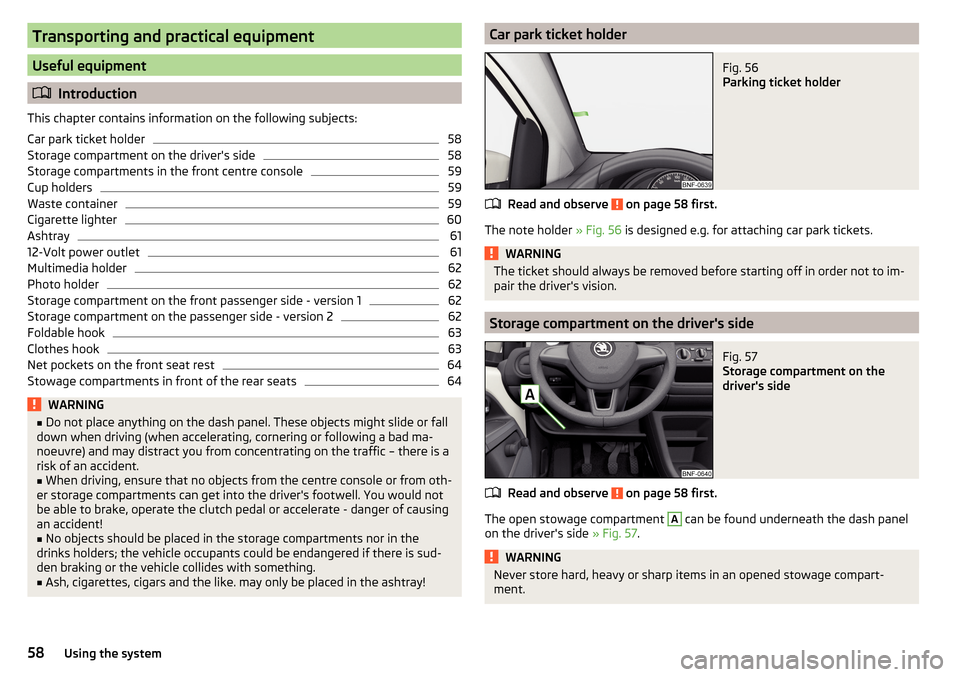
Car park ticket holderFig. 56
Parking ticket holder
Read and observe on page 58 first.
The note holder » Fig. 56 is designed e.g. for attaching car park tickets.
WARNINGThe ticket should always be removed before starting off in order not to im-
pair the driver's vision.
Storage compartment on the driver's side
Fig. 57
Storage compartment on the
driver's side
Read and observe on page 58 first.
The open stowage compartment
A
can be found underneath the dash panel
on the driver's side » Fig. 57.
WARNINGNever store hard, heavy or sharp items in an opened stowage compart-
ment.58Using the system
Page 78 of 160
Lock/unlock steering lockRead and observe
and on page 75 first.
The steering lock (steering lock) deters any attempted theft of your vehicle.
Locking
›
Withdraw the ignition key.
›
Turn the steering wheel to the left or right until the steering lock clicks into
place.
Unlocking
›
Insert the key into the ignition lock.
›
Switch on the ignition » page 76.
The steering lock is unlocked.
If the ignition switch cannot be turned on, then turn the steering wheel back and forth slightly and thereby unlock the steering lock.
Ignition on / off and start the engine
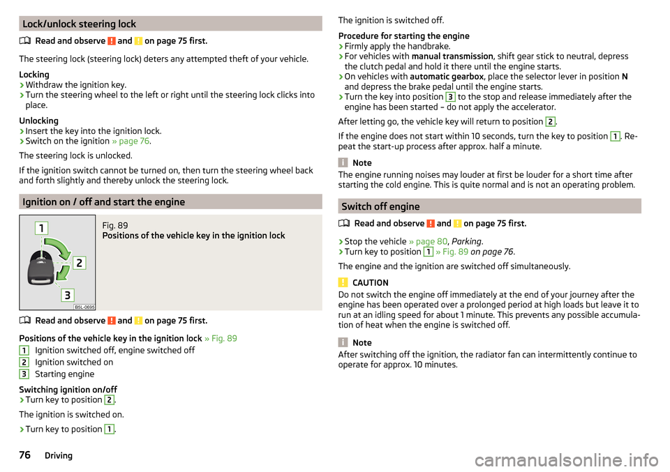
Fig. 89
Positions of the vehicle key in the ignition lock
Read and observe and on page 75 first.
Positions of the vehicle key in the ignition lock » Fig. 89
Ignition switched off, engine switched off
Ignition switched on
Starting engine
Switching ignition on/off
›
Turn key to position
2
.
The ignition is switched on.
›
Turn key to position
1
.
123The ignition is switched off.
Procedure for starting the engine›
Firmly apply the handbrake.
›
For vehicles with manual transmission , shift gear stick to neutral, depress
the clutch pedal and hold it there until the engine starts.
›
On vehicles with automatic gearbox , place the selector lever in position N
and depress the brake pedal until the engine starts.
›
Turn the key into position
3
to the stop and release immediately after the
engine has been started – do not apply the accelerator.
After letting go, the vehicle key will return to position
2
.
If the engine does not start within 10 seconds, turn the key to position
1
. Re-
peat the start-up process after approx. half a minute.
Note
The engine running noises may louder at first be louder for a short time after
starting the cold engine. This is quite normal and is not an operating problem.
Switch off engine
Read and observe
and on page 75 first.
›
Stop the vehicle » page 80, Parking .
›
Turn key to position
1
» Fig. 89 on page 76 .
The engine and the ignition are switched off simultaneously.
CAUTION
Do not switch the engine off immediately at the end of your journey after the
engine has been operated over a prolonged period at high loads but leave it to
run at an idling speed for about 1 minute. This prevents any possible accumula-
tion of heat when the engine is switched off.
Note
After switching off the ignition, the radiator fan can intermittently continue to
operate for approx. 10 minutes.76Driving
Page 79 of 160
START-STOPsystem
Introduction
This chapter contains information on the following subjects:
Operation
77
Manually deactivating/activating the system
78
The START-STOPsystem (hereinafter referred to as: the system) reduces CO 2emissions and harmful emissions, and saves fuel.
If the system determine that the engine is not needed when the vehicle stops
(e.g. at the traffic lights), it turns off the engine and starts it again when mov-
ing off.
The system function depends on many factors. Some of them are down to the
driver, the others are systemic and can neither be influenced nor identified.
Therefore the system may react differently in situations which seem identi-
cal from the driver's perspective.
The system is automatically activated every time the ignition is switched on
(even where this has previously been manually deactivated with the button
).
Note
If the engine has stopped due to the system, the ignition remains on.
Operation
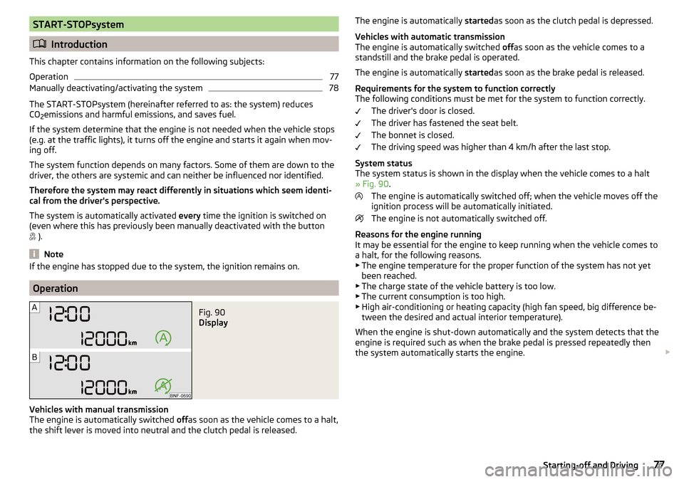
Fig. 90
Display
Vehicles with manual transmission
The engine is automatically switched offas soon as the vehicle comes to a halt,
the shift lever is moved into neutral and the clutch pedal is released.
The engine is automatically startedas soon as the clutch pedal is depressed.
Vehicles with automatic transmission
The engine is automatically switched offas soon as the vehicle comes to a
standstill and the brake pedal is operated.
The engine is automatically startedas soon as the brake pedal is released.
Requirements for the system to function correctly
The following conditions must be met for the system to function correctly.
The driver's door is closed.
The driver has fastened the seat belt.
The bonnet is closed.
The driving speed was higher than 4 km/h after the last stop.
System status
The system status is shown in the display when the vehicle comes to a halt
» Fig. 90 .
The engine is automatically switched off; when the vehicle moves off the
ignition process will be automatically initiated.
The engine is not automatically switched off.
Reasons for the engine running
It may be essential for the engine to keep running when the vehicle comes to
a halt, for the following reasons. ▶ The engine temperature for the proper function of the system has not yet
been reached.
▶ The charge state of the vehicle battery is too low.
▶ The current consumption is too high.
▶ High air-conditioning or heating capacity (high fan speed, big difference be-
tween the desired and actual interior temperature).
When the engine is shut-down automatically and the system detects that the
engine is required such as when the brake pedal is pressed repeatedly then
the system automatically starts the engine. 77Starting-off and Driving
Page 80 of 160
Note■If the vehicle remains outdoors for a long time in minus temperatures or in
direct sunlight, it can take several hours until the internal temperature of the
vehicle battery reaches a suitable temperature for proper operation of the
START STOP system.■
If the driver's seat belt is removed for more than approx. 30 seconds or the
driver's door is opened during stop mode, the engine will have to be started
manually.
■
No automatic engine shut-down takes place when a vehicle with automatic
transmission is moving at low speed (e.g. during a traffic jam) and remains sta-
tionary after pressing the brake pedal lightly. Automatic engine shutdown
takes place if you press the brake pedal down with more force.
■
For vehicles with automatic transmission there is no automatic engine shut-
down when the system detects a manoeuvring action due to a large steering
angle.
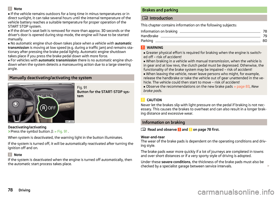
Manually deactivating/activating the system
Fig. 91
Button for the START-STOP sys-
tem
Deactivating/activating
›
Press the symbol button
» Fig. 91 .
When system is deactivated, the warning light in the button illuminates.
If the system is turned off, it will be automatically reactivated after turning the
ignition off and on.
Note
If the system is deactivated when the engine is turned off automatically, then
the automatic start process takes place.Brakes and parking
Introduction
This chapter contains information on the following subjects:
Information on braking
78
Handbrake
79
Parking
80WARNING■ Greater physical effort is required for braking when the engine is switch-
ed off – risk of accident!■
When braking in a vehicle with manual transmission, when the vehicle is
in gear and at low revs, the clutch pedal must be depressed. Otherwise, the
functionality of the brake system may be impaired – risk of accident!
■
When leaving the vehicle, never leave persons who might, for example,
release the handbrake or take the vehicle out of gear unattended in the ve-
hicle. The vehicle could then start to move – risk of accident!
■
Observe the recommendations on the new brake pads » page 83, New
brake pads .
CAUTION
Never let the brakes slip with light pressure on the pedal if braking is not nec-
essary. This causes the brakes to overheat and can also result in a longer brak-
ing distance and excessive wear.
Information on braking
Read and observe
and on page 78 first.
Wear-and-tear
The wear of the brake pads is dependent on the operating conditions and driv-
ing style.
The brake pads wear more quickly if a lot of journeys are completed in towns
and over short distances or if a very sporty style of driving is adopted.
Under these severe conditions , the thickness of the brake pads must also be
checked by a specialist garage between service intervals.
78Driving
Page 82 of 160
WARNINGPlease note that the handbrake must be fully released. A handbrake which
is only partially released can result in the rear brakes overheating. This can
have a negative effect on the operation of the brake system – risk of acci-
dent!
Parking
Read and observe
and on page 78 first.
When stopping and parking, look for a place with a suitable surface » .
Only carry out the activities while parking in the specified order.
›
Bring the vehicle to a stop and depress the brake pedal.
›
Firmly apply the handbrake.
›
For vehicles with automated gearbox shift the lever to position D or R.
›
Switch off the engine.
›
For vehicles with manual transmission select 1st gear or reverse gear (R) .
›
Release the brake pedal.
WARNINGThe parts of the exhaust system can become very hot. Therefore, never
stop the vehicle at places where the underside of your vehicle can come in-
to contact with flammable materials such as dry grass, undergrowth,
leaves, spilled fuel or such like. - Risk of fire and serious injury can occur!
Manual gear changing and pedals
Introduction
This chapter contains information on the following subjects:
Manual gear changing
80
Pedals
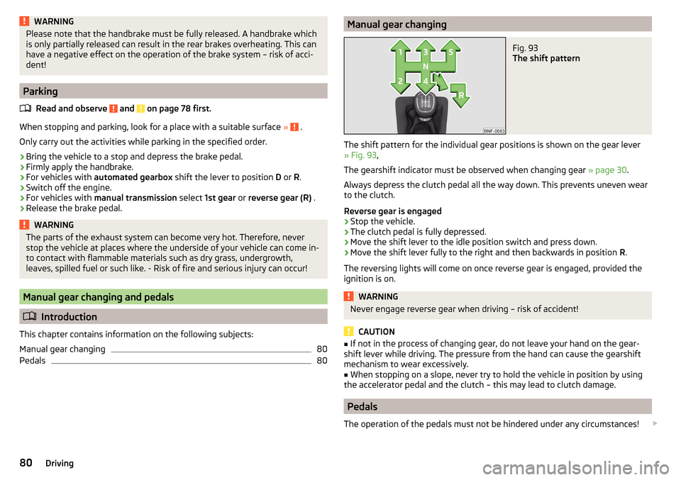
80Manual gear changingFig. 93
The shift pattern
The shift pattern for the individual gear positions is shown on the gear lever » Fig. 93 ,
The gearshift indicator must be observed when changing gear » page 30.
Always depress the clutch pedal all the way down. This prevents uneven wear
to the clutch.
Reverse gear is engaged
›
Stop the vehicle.
›
The clutch pedal is fully depressed.
›
Move the shift lever to the idle position switch and press down.
›
Move the shift lever fully to the right and then backwards in position R.
The reversing lights will come on once reverse gear is engaged, provided the
ignition is on.
WARNINGNever engage reverse gear when driving – risk of accident!
CAUTION
■ If not in the process of changing gear, do not leave your hand on the gear-
shift lever while driving. The pressure from the hand can cause the gearshift
mechanism to wear excessively.■
When stopping on a slope, never try to hold the vehicle in position by using
the accelerator pedal and the clutch – this may lead to clutch damage.
Pedals
The operation of the pedals must not be hindered under any circumstances!
80Driving
Page 90 of 160
Note■The visual parking system is shown in the screen of the multifunction device
Move & Fun within a few seconds of shifting into reverse gear.■
More information about the mobile multifunction device Move & Fun can be
found in the digital Owner´s Manual in the device » page 72, Multifunction de-
vice Move & Fun - install/remove .
Cruise Control System
Introduction
This chapter contains information on the following subjects:
Functioning
88
Operating Description
88
The Cruise Control System (CCS) maintains a set speed without you having to
actuate the accelerator pedal.
The state where the GRA maintains the speed is referred to hereinafter as the
control .
WARNINGThe general information relating to the use of assistance systems must be
observed » page 85, in section Introduction .
Functioning
Read and observe
on page 88 first.
Basic requirements for start of control The GRA is activated.
On vehicles with a manual transmission , the second gear or higher is en-
gaged.
On vehicles with an automatic transmission , the selector lever is in the D
position or in the Tiptronic position.
The current speed is higher than approx. 20 km/h.
This is only possible within the range which is permitted by the power output
and braking power of the engine.
WARNINGIf the engine power and engine braking effect is insufficient to maintain
the set speed, vehicle operation must be taken over!
Operating Description
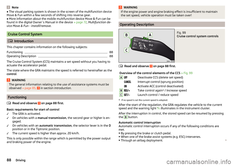
Fig. 99
Cruise control system controls
Read and observe on page 88 first.
Overview of the control elements of the CCS » Fig. 99ADeactivate CCS (delete set speed) Interrupt control (sprung position) Activate ACC (control deactivated)BTake control again a)
/ Increase speedCLaunch control / reduce speeda)
If no speed is set the current speed is adopted.
After the start of the regulation, the GRA regulates the vehicle to the current
speed and the warning light
illuminates in the instrument cluster.
After the interruption in control, the stored speed can be resumed by pressing
the
B
button.
Automatic control interruption
Automatic control interruption occurs if any of the following conditions are
met.
▶ By pressing the brake or clutch pedal.
▶ When one of the brake assist systems (e.g. ESC) intervenes.
▶ Through an airbag deployment.
88Driving
Page 91 of 160
WARNING■Always deactivate the cruise control system after use to prevent the sys-
tem being switched on unintentionally.■
Control may only be resumed if the set speed is not too high for the cur-
rent traffic conditions.
Note
During control, speed can be increased by pressing the accelerator pedal. Re-
leasing the accelerator pedal will cause the speed to drop again to the set
speed.
City Safe Drive
Introduction
This chapter contains information on the following subjects:
Operation
89
Disable / Enable
90
City Safe Drive (hereinafter referred to as: the system) monitors the traffic sit-
uation ahead of the vehicle. If the system detects a risk of collision with an ob-
stacle ahead of the vehicle, then automatic braking is applied. The risk of a col-
lision is thus reduced and the consequences of an impact are minimized.
WARNING■ The general information relating to the use of assistance systems must
be observed » page 85, in section Introduction .■
The system does not respond to crossing or oncoming objects.
CAUTION
The system can slow down the vehicle to a standstill. If the vehicle continues
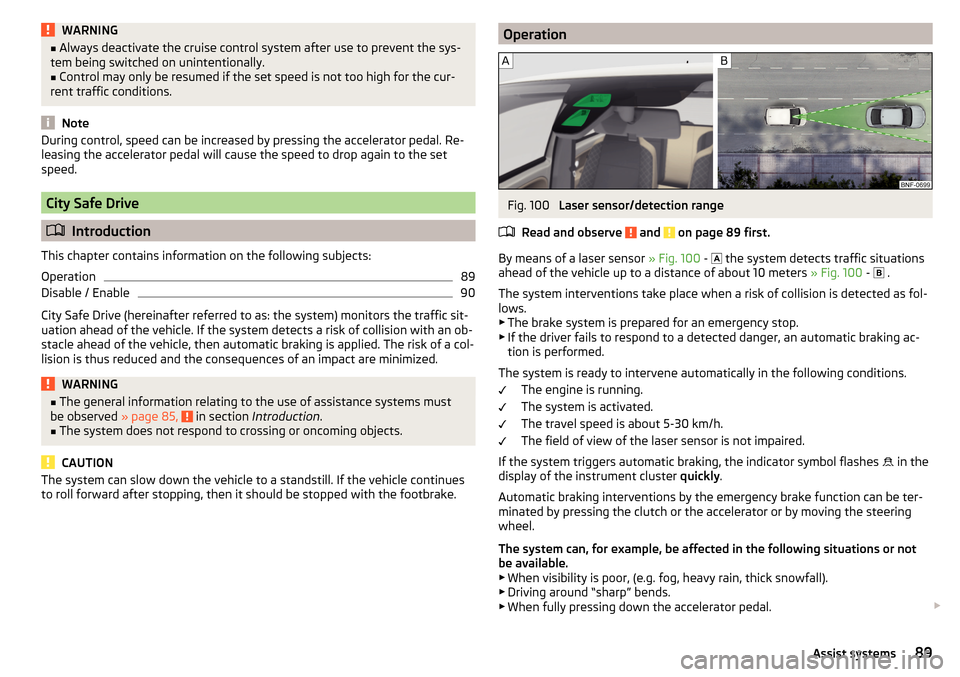
to roll forward after stopping, then it should be stopped with the footbrake.OperationFig. 100
Laser sensor/detection range
Read and observe
and on page 89 first.
By means of a laser sensor » Fig. 100 -
the system detects traffic situations
ahead of the vehicle up to a distance of about 10 meters » Fig. 100 -
.
The system interventions take place when a risk of collision is detected as fol-
lows.
▶ The brake system is prepared for an emergency stop.
▶ If the driver fails to respond to a detected danger, an automatic braking ac-
tion is performed.
The system is ready to intervene automatically in the following conditions. The engine is running.
The system is activated.
The travel speed is about 5-30 km/h.
The field of view of the laser sensor is not impaired.
If the system triggers automatic braking, the indicator symbol flashes in the
display of the instrument cluster quickly.
Automatic braking interventions by the emergency brake function can be ter-
minated by pressing the clutch or the accelerator or by moving the steering
wheel.
The system can, for example, be affected in the following situations or not
be available. ▶ When visibility is poor, (e.g. fog, heavy rain, thick snowfall).
▶ Driving around “sharp” bends.
▶ When fully pressing down the accelerator pedal.
89Assist systems
Page 132 of 160
›Attach clamp 3 to the negative terminal of the battery supplying power B.›Attach the clamp 4 to a solid metal component firmly connected to the en-
gine block or to the engine block itself.
On vehicles with the START-STOPsystem the jump-start cable must be con-
nected to the engine earthing point » Fig. 125.
Starting engine›
Start the engine on the vehicle providing the power and allow it to idle.
›
Start the engine of the vehicle with the discharged battery.
›
If the engine does not start, halt the attempt to start the engine after 10 sec-
onds and wait for 30 seconds before repeating the process.
›
Remove the jump start cables in the reverse order as attachment.
Both batteries must have a rated voltage of 12 V. The capacity (Ah) of the bat-
tery supplying the power must not be significantly less than the capacity of
the discharged battery in your vehicle.
Jump-start cables
Only use jump-start cables which have an adequately large cross-section and
insulated terminal clamps. Observe the instructions of the jumper lead manu-
facturer.
Positive cable – colour coding in the majority of cases is red.
Negative cable – colour coding in the majority of cases is black.
WARNING■
Do not clamp the jump-start cable to the negative terminal of the dis-
charged battery. There is the risk of detonating gas seeping out the battery
being ignited by the strong spark which results from the engine being star-
ted.■
The non-insulated parts of the terminal clamps must never touch each
other – there is a risk of short circuit.
■
The jump-start cable connected to the positive terminal of the battery
must not come into contact with electrically conducting parts of the vehicle
– there is a risk of short circuit.
■
Route the jump-start cables so that they cannot be caught by any rotat-
ing parts in the engine compartment.
Towing the vehicle
Introduction
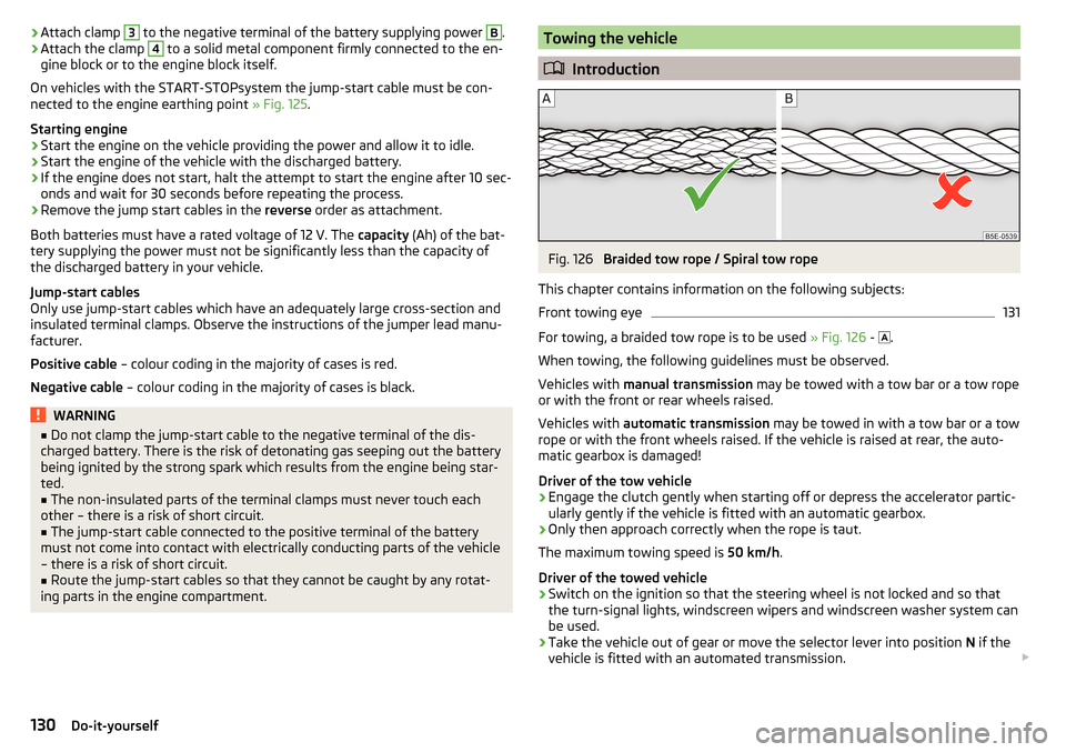
Fig. 126
Braided tow rope / Spiral tow rope
This chapter contains information on the following subjects:
Front towing eye
131
For towing, a braided tow rope is to be used » Fig. 126 -
.
When towing, the following guidelines must be observed.
Vehicles with manual transmission may be towed with a tow bar or a tow rope
or with the front or rear wheels raised.
Vehicles with automatic transmission may be towed in with a tow bar or a tow
rope or with the front wheels raised. If the vehicle is raised at rear, the auto-
matic gearbox is damaged!
Driver of the tow vehicle
›
Engage the clutch gently when starting off or depress the accelerator partic-
ularly gently if the vehicle is fitted with an automatic gearbox.
›
Only then approach correctly when the rope is taut.
The maximum towing speed is 50 km/h.
Driver of the towed vehicle
›
Switch on the ignition so that the steering wheel is not locked and so that
the turn-signal lights, windscreen wipers and windscreen washer system can
be used.
›
Take the vehicle out of gear or move the selector lever into position N if the
vehicle is fitted with an automated transmission.
130Do-it-yourself