wheel torque SKODA CITIGO 2015 1.G Owner's Manual
[x] Cancel search | Manufacturer: SKODA, Model Year: 2015, Model line: CITIGO, Model: SKODA CITIGO 2015 1.GPages: 160, PDF Size: 23.1 MB
Page 128 of 160

The mounting points are located on the metal bar of the lower sill on the un-
derside of your vehicle. The positions of these are embossed by means of
markings on the side surface of the lower sill » Fig. 122.âș
Support the base plate of the jack with its full area resting on level ground
and ensure that the jack is located in a vertical position at the jacking point
» Fig. 123 - ï
.
âș
Position the lifting jack below the jacking point with the crank and move it up
until its claw encloses the web » Fig. 123 - ï
.
âș
Continue turning up the jack until the wheel is just about lifted off the
ground.
WARNINGâ If the wheel has to be changed on a slope, first of all block the opposite
wheel with a stone or similar object to prevent the vehicle from unexpect-
edly rolling away.â
Secure the base plate of the lifting jack with suitable means to prevent
possible moving. A soft and slippery ground under the base plate may move
the lifting jack, causing the vehicle to fall down. It is therefore always nec-
essary to place the lifting jack on a solid surface or use a wide and stable
base. If the surface is smooth, such as on cobbled stones, tiled floor etc.,
use a non-slip base (e.g. a rubber foot mat).
â
Only attach the lifting jack to the attachment points provided for this pur-
pose.
â
Always raise the vehicle with the doors closed.
â
Never position any body parts, such as arms or legs under the vehicle,
while the vehicle is raised with a lifting jack.
â
When the vehicle is raised, never start the engine.
CAUTION
It is important to ensure that the jack is correctly attached to the web of the
lower fork leg - risk of damage to the vehicle.
Remove the wheel / fix
When changing a wheel, the following instructions must be followed.
âș
Remove the full wheel trim or the caps of the wheel bolts.
âș
First of all slacken the anti-theft wheel bolt and then the other wheel bolts.
âș
Jack up the vehicle until the wheel that needs changing is clear of the
ground.
âș Unscrew the wheel bolts and place them on a clean surface (cloth, paper,
etc.).âș
Remove the wheel carefully.
âș
Attach the wheel and slightly screw on the wheel bolts.
âș
Lower the vehicle.
âș
Alternately tighten wheel bolts opposite (diagonally) with the wheel wrench.
Tighten the anti-theft wheel bolt last.
âș
Replace the wheel trim or the caps.
When fitting unidirectional tyres, ensure that the direction of rotation is cor-
rect » page 119 .
All bolts must be clean and must turn easily.
If it is established when changing a wheel that the wheel bolts are corroded and difficult to move, then these must be replaced.
Under no circumstances grease or oil the wheel bolts!
WARNINGUndo the wheel bolts only a little (about one turn) provided that the vehicle
has not yet been jacked up. Otherwise the wheel could become loose and
fall off.
Follow-up work
After changing the wheel, the following work must be carried out.
âș
Stow the replaced wheel in the wheel well and secure it with a special nut.
âș
Stow the tool kit in the space provided and secure using the band.
âș
Check the tyre pressure on the fitted wheel as soon as possible.
âș
Have the tightening torque of the wheel bolts checked with a torque wrench
as soon as possible.
After changing the wheel, the tyre pressure should be adjusted. In vehicles
with tyre pressure monitoring, save tyre pressure values » page 91.
Replace the damaged wheel or consult a specialist garage about repair op-
tions.
The prescribed tightening torque of the wheel bolts is 110 Nm. ïŁ
126Do-it-yourself
Page 129 of 160

WARNINGâ If the wheel bolts are tightened to a too low tightening torque, the rim
can come loose when the car is moving. A tightening torque which is too
high can damage the bolts and threads and this can result in permanent
deformation of the contact surfaces on the rim.â
Drive cautiously and only at a moderate speed until the tightening torque
has been checked.
Puncture repair kit
ï€ Introduction
This chapter contains information on the following subjects:
Components of the puncture repair kits
127
General information
128
Preparations for using the breakdown kit
128
Sealing and inflating the tyre
128
Notes for driving with repaired tyres
129
Use the breakdown kit to reliably repair tyre damage caused by foreign bodies
or a puncture with diameters up to approx. 4 mm.
A repair made using the breakdown kit is never intended to replace a perma-
nent repair on the tyre. Its purpose is to get you to the nearest specialist ga-
rage.
The wheel must not be removed during repair.
Do not remove foreign bodies , which have penetrated the wheel profile from
the tyre (e.g. screws or nails).
Immediately replace the tyre that was repaired using the breakdown kit, or
consult a specialist garage about repair options.
WARNINGâ The sealant is hazardous to heath. Remove immediately if it comes into
contact with the skin.â
Observe the manufacturer's usage instructions for the breakdown kit.
Note
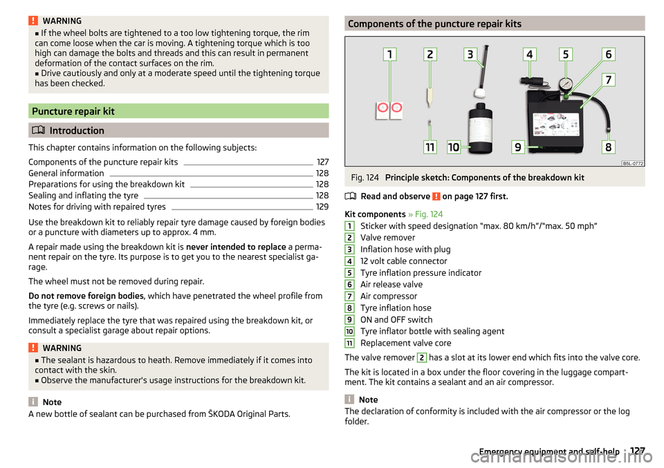
A new bottle of sealant can be purchased from Ć KODA Original Parts.Components of the puncture repair kitsFig. 124
Principle sketch: Components of the breakdown kit
Read and observe
on page 127 first.
Kit components » Fig. 124
Sticker with speed designation âmax. 80 km/hâ/âmax. 50 mphâ
Valve remover
Inflation hose with plug
12 volt cable connector
Tyre inflation pressure indicator
Air release valve
Air compressor
Tyre inflation hose
ON and OFF switch
Tyre inflator bottle with sealing agent
Replacement valve core
The valve remover
2
has a slot at its lower end which fits into the valve core.
The kit is located in a box under the floor covering in the luggage compart-
ment. The kit contains a sealant and an air compressor.
Note
The declaration of conformity is included with the air compressor or the log
folder.ï€1234567891011127Emergency equipment and self-help