buttons SKODA CITIGO 2015 1.G Owner's Manual
[x] Cancel search | Manufacturer: SKODA, Model Year: 2015, Model line: CITIGO, Model: SKODA CITIGO 2015 1.GPages: 160, PDF Size: 23.1 MB
Page 29 of 160
Using the system
Cockpit
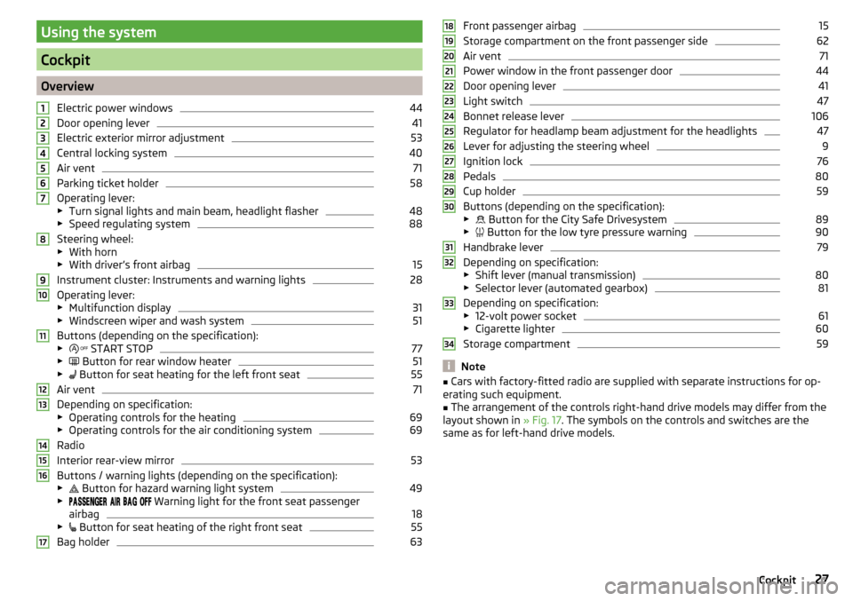
OverviewElectric power windows
44
Door opening lever
41
Electric exterior mirror adjustment
53
Central locking system
40
Air vent
71
Parking ticket holder
58
Operating lever:
▶ Turn signal lights and main beam, headlight flasher
48
▶Speed regulating system
88
Steering wheel:
▶ With horn
▶ With driver’s front airbag
15
Instrument cluster: Instruments and warning lights
28
Operating lever:
▶ Multifunction display
31
▶Windscreen wiper and wash system
51
Buttons (depending on the specification):
▶ START STOP
77
▶
Button for rear window heater
51
▶
Button for seat heating for the left front seat
55
Air vent
71
Depending on specification:
▶ Operating controls for the heating
69
▶Operating controls for the air conditioning system
69
Radio
Interior rear-view mirror
53
Buttons / warning lights (depending on the specification):
▶ Button for hazard warning light system
49
▶
Warning light for the front seat passenger
airbag
18
▶ Button for seat heating of the right front seat
55
Bag holder
631234567891011121314151617Front passenger airbag15
Storage compartment on the front passenger side
62
Air vent
71
Power window in the front passenger door
44
Door opening lever
41
Light switch
47
Bonnet release lever
106
Regulator for headlamp beam adjustment for the headlights
47
Lever for adjusting the steering wheel
9
Ignition lock
76
Pedals
80
Cup holder
59
Buttons (depending on the specification):
▶ Button for the City Safe Drivesystem
89
▶
Button for the low tyre pressure warning
90
Handbrake lever
79
Depending on specification:
▶ Shift lever (manual transmission)
80
▶Selector lever (automated gearbox)
81
Depending on specification:
▶ 12-volt power socket
61
▶Cigarette lighter
60
Storage compartment
59
Note
■Cars with factory-fitted radio are supplied with separate instructions for op-
erating such equipment.■
The arrangement of the controls right-hand drive models may differ from the
layout shown in » Fig. 17. The symbols on the controls and switches are the
same as for left-hand drive models.
181920212223242526272829303132333427Cockpit
Page 33 of 160
The arrow symbol is shown after the name of the engaged gear.- Recommends that you change up to a higher gear
- Recommends that you change down to a lower gear
Gear recommendation - vehicles with manual transmission
The recommended gear and the arrow icon is displayed.
If e.g.
appears, this means it would be beneficial to change up from a lower
gear into 3rd gear.
Gear recommendation - vehicles with automated manual transmission mode
for manual gearshifting (Tiptronic)
The currently engaged gear and the relevant arrow icon is displayed.
If .g
appears, this means it would be beneficial to change up from 3rd gear
to a higher gearWARNINGThe driver is always responsible for selecting the correct gear in different
driving situations, such as overtaking.
Multi-function display (MFD)
Introduction
This chapter contains information on the following subjects:
Operation
31
Multifunction display details
31
Warning at excessive speeds
32
Memory
33
33
The driving data is displayed on the multifunction display.
The multifunction display only operates if the ignition is switched on. After the ignition is switched on, the function that was last selected before switching
off the ignition is displayed.
WARNING■ Concentrate fully at all times on your driving! As the driver you are fully
responsible for the operation of your vehicle.■
Even at temperatures of around +4 °C, black ice may still be on the road
surface! You should therefore not only rely on the outside temperature dis-
play for accurate information as to whether there is ice on the road.
Operation
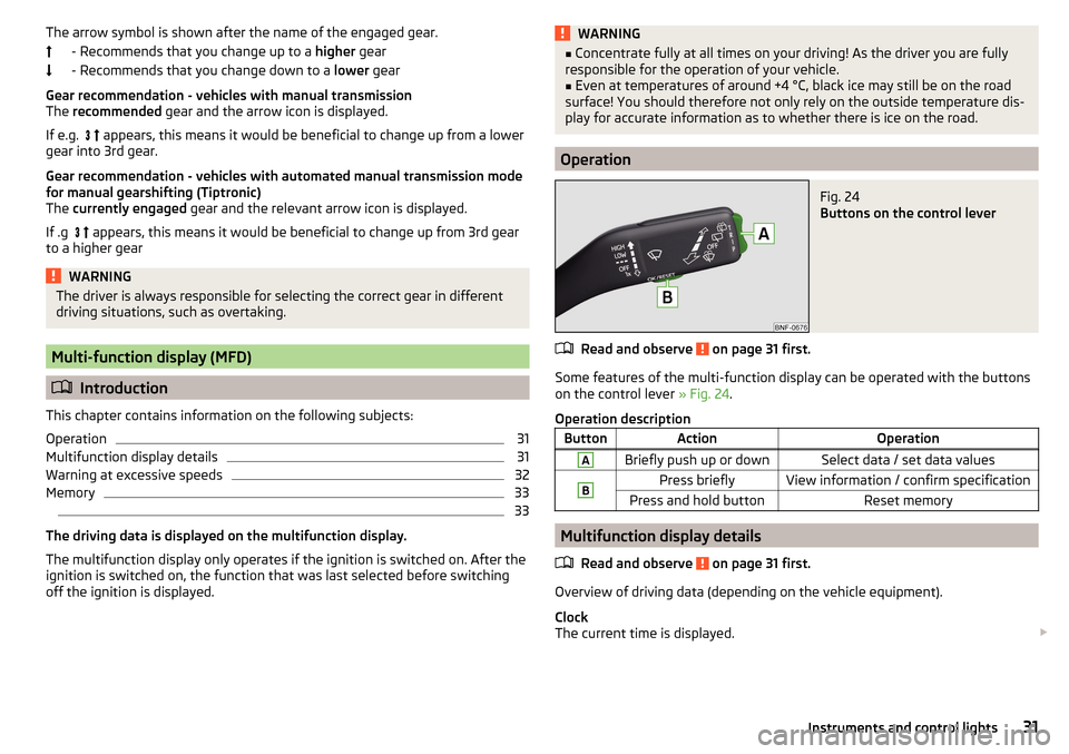
Fig. 24
Buttons on the control lever
Read and observe on page 31 first.
Some features of the multi-function display can be operated with the buttons
on the control lever » Fig. 24.
Operation description
ButtonActionOperationABriefly push up or downSelect data / set data valuesBPress brieflyView information / confirm specificationPress and hold buttonReset memory
Multifunction display details
Read and observe
on page 31 first.
Overview of driving data (depending on the vehicle equipment).
Clock
The current time is displayed.
31Instruments and control lights
Page 35 of 160
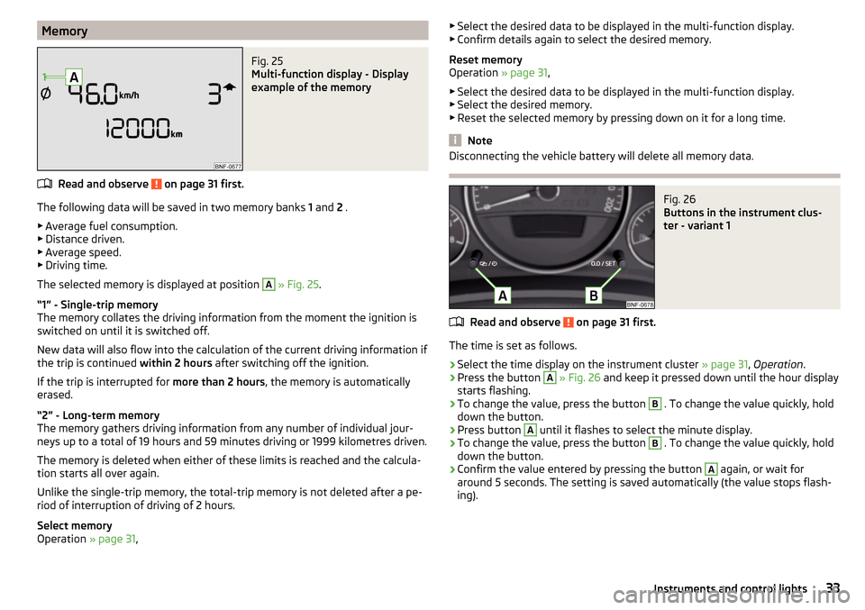
MemoryFig. 25
Multi-function display - Display
example of the memory
Read and observe on page 31 first.
The following data will be saved in two memory banks 1 and 2 .
▶ Average fuel consumption.
▶ Distance driven.
▶ Average speed.
▶ Driving time.
The selected memory is displayed at position
A
» Fig. 25 .
“1” - Single-trip memory
The memory collates the driving information from the moment the ignition is
switched on until it is switched off.
New data will also flow into the calculation of the current driving information if
the trip is continued within 2 hours after switching off the ignition.
If the trip is interrupted for more than 2 hours, the memory is automatically
erased.
“2” - Long-term memory
The memory gathers driving information from any number of individual jour-
neys up to a total of 19 hours and 59 minutes driving or 1999 kilometres driven.
The memory is deleted when either of these limits is reached and the calcula-
tion starts all over again.
Unlike the single-trip memory, the total-trip memory is not deleted after a pe-
riod of interruption of driving of 2 hours.
Select memory
Operation » page 31,
▶
Select the desired data to be displayed in the multi-function display.
▶ Confirm details again to select the desired memory.
Reset memory
Operation » page 31,
▶ Select the desired data to be displayed in the multi-function display.
▶ Select the desired memory.
▶ Reset the selected memory by pressing down on it for a long time.
Note
Disconnecting the vehicle battery will delete all memory data.Fig. 26
Buttons in the instrument clus-
ter - variant 1
Read and observe on page 31 first.
The time is set as follows.
›
Select the time display on the instrument cluster » page 31, Operation .
›
Press the button
A
» Fig. 26 and keep it pressed down until the hour display
starts flashing.
›
To change the value, press the button
B
. To change the value quickly, hold
down the button.
›
Press button
A
until it flashes to select the minute display.
›
To change the value, press the button
B
. To change the value quickly, hold
down the button.
›
Confirm the value entered by pressing the button
A
again, or wait for
around 5 seconds. The setting is saved automatically (the value stops flash-
ing).
33Instruments and control lights
Page 46 of 160
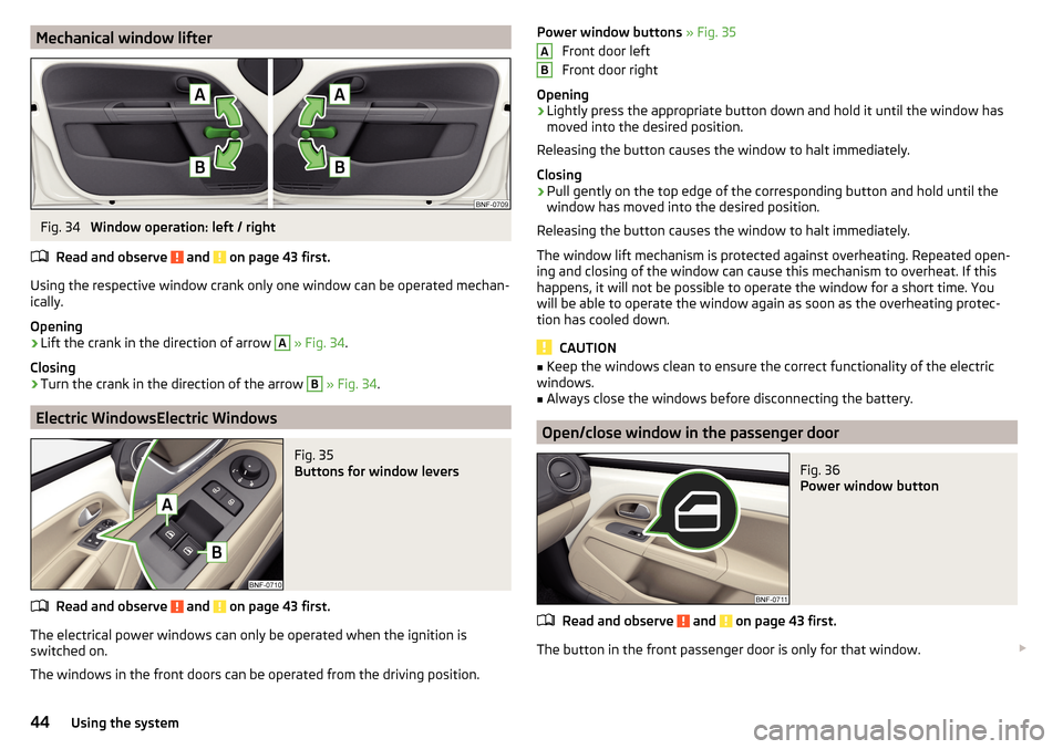
Mechanical window lifterFig. 34
Window operation: left / right
Read and observe
and on page 43 first.
Using the respective window crank only one window can be operated mechan-
ically.
Opening
›
Lift the crank in the direction of arrow
A
» Fig. 34 .
Closing
›
Turn the crank in the direction of the arrow
B
» Fig. 34 .
Electric WindowsElectric Windows
Fig. 35
Buttons for window levers
Read and observe and on page 43 first.
The electrical power windows can only be operated when the ignition is
switched on.
The windows in the front doors can be operated from the driving position.
Power window buttons » Fig. 35
Front door left
Front door right
Opening›
Lightly press the appropriate button down and hold it until the window has
moved into the desired position.
Releasing the button causes the window to halt immediately.
Closing
›
Pull gently on the top edge of the corresponding button and hold until the
window has moved into the desired position.
Releasing the button causes the window to halt immediately.
The window lift mechanism is protected against overheating. Repeated open-
ing and closing of the window can cause this mechanism to overheat. If this
happens, it will not be possible to operate the window for a short time. You
will be able to operate the window again as soon as the overheating protec-
tion has cooled down.
CAUTION
■ Keep the windows clean to ensure the correct functionality of the electric
windows.■
Always close the windows before disconnecting the battery.
Open/close window in the passenger door
Fig. 36
Power window button
Read and observe and on page 43 first.
The button in the front passenger door is only for that window.
AB44Using the system
Page 57 of 160
WARNINGPlease note the following points about the head restraint settings
» page 8 , Correct and safe seated position .
Note
The front headrests are integrated into the seat backrests and cannot be ad-
justed in height.
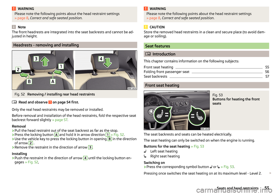
Headrests - removing and installing
Fig. 52
Removing / installing rear head restraints
Read and observe
on page 54 first.
Only the real head restraints may be removed or installed.
Before removal and installation of the head restraints, fold the respective seat
backrest forward slightly » page 57.
Removal
›
Pull the head restraint out of the seat backrest as far as the stop.
›
Press the locking button
A
and hold it in arrow direction
1
» Fig. 52 .
›
Use the vehicle key to press the locking button in opening
B
in the direction
of arrow
2
.
›
Remove the restraint in the direction of arrow
3
.
Installing
›
Push the restraint in the direction of arrow
4
until the locking button en-
gages » Fig. 52 ,
WARNINGPlease note the following points about the head restraint settings
» page 8 , Correct and safe seated position .
CAUTION
Store the removed head restraints in a clean and secure place (to avoid dam-
age or soiling).
Seat features
Introduction
This chapter contains information on the following subjects:
Front seat heating
55
Folding front passenger seat
56
Seat backrests
57
Front seat heating
Fig. 53
Buttons for heating the front
seats
The seat backrests and seats can be heated electrically.
The seat heating can only be switched on when the engine is running.
Buttons for the seat heating » Fig. 53
Left seat heating
Right seat heating
Switching on
›
Press the corresponding symbol button
or
» Fig. 53 .
Pressing once switches the seat heating on at its maximum level - Level 2.
55Seats and head restraints
Page 134 of 160
Remote control
Introduction
This chapter contains information on the following subjects:
Replacing the battery in the remote control key
132
Synchronising the remote control
132
CAUTION
■ The replacement battery must have the same specification as the original
battery.■
We recommend having faulty rechargeable batteries replaced by a ŠKODA
service partner.
■
Pay attention to the correct polarity when changing the battery.
Note
If a key has an affixed decorative cover, this will be destroyed when the bat-
tery is replaced. A replacement cover can be purchased from a ŠKODA Partner.
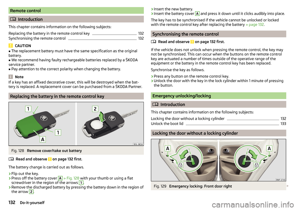
Replacing the battery in the remote control key
Fig. 128
Remove cover/take out battery
Read and observe
on page 132 first.
The battery change is carried out as follows.
›
Flip out the key.
›
Press off the battery cover
A
» Fig. 128 with your thumb or using a flat
screwdriver in the region of the arrows
1
.
›
Remove the discharged battery by pressing the battery down in the region of
the arrow
2
.
› Insert the new battery.›Insert the battery cover A and press it down until it clicks audibly into place.
The key has to be synchronised if the vehicle cannot be unlocked or locked
with the remote control key after replacing the battery » page 132.
Synchronising the remote control
Read and observe
on page 132 first.
If the vehicle does not unlock when pressing the remote control, the key may
not be synchronised. This can occur when the buttons on the remote control
key are actuated a number of times outside of the operative range of the
equipment or the battery in the remote control key has been replaced.
Synchronise the key as follows.
›
Press any button on the remote control key.
›
Unlock the door with the key in the lock cylinder within 1 minute of pressing the button.
Emergency unlocking/locking
Introduction
This chapter contains information on the following subjects:
Locking the door without a locking cylinder
132
Unlock the boot lid
133
Locking the door without a locking cylinder
Fig. 129
Emergency locking: Front door right
132Do-it-yourself
Page 139 of 160
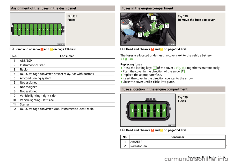
Assignment of the fuses in the dash panelFig. 137
Fuses
Read and observe and on page 134 first.
No.Consumer1ABS/ESP2Instrument cluster3Radio4DC-DC voltage converter, starter relay, bar with buttons5Air conditioning system6Not assigned7Not assigned8Not assigned9Vehicle lighting - right side10Vehicle lighting - left side11Starter12DC-DC voltage converter, ABS, instrument cluster, radioFuses in the engine compartmentFig. 138
Remove the fuse box cover.
Read and observe and on page 134 first.
The fuses are located underneath a cover next to the vehicle battery
» Fig. 138 .
Replacing fuses
›
Press the locking keys
1
of the cover » Fig. 138 together simultaneously.
›
Push the cover in the direction of the arrow
2
.
›
Replace the appropriate fuse.
›
Insert the cover in the direction counter to the arrow.
›
Close the cover until it clicks into place.
Fuse allocation in the engine compartment
Fig. 139
Fuses
Read and observe and on page 134 first.
No.Consumer1ABS/ESP2Radiator fan 137Fuses and light bulbs