air condition SKODA CITIGO 2017 Owner's Manual
[x] Cancel search | Manufacturer: SKODA, Model Year: 2017, Model line: CITIGO, Model: SKODA CITIGO 2017Pages: 172, PDF Size: 24.54 MB
Page 114 of 172
WARNING (Continued)■Do not manipulate individual parts of the airbag system, as this might re-
sult in the airbag being deployed.■
If the airbag has been deployed, the airbag system must be replaced.
WARNINGThe airbag system operates using pressure sensors located in the front
doors. For this reason, no adjustments may be carried out to the doors or
door panels (e.g. installation of additional loudspeakers). Resulting damage
can impair the functioning of the airbag system - risk of accidents and fatal
injuries! The following guidelines must therefore be observed.■
Any work on the front doors and their door panels must be carried out by
a specialist garage.
■
Never drive the vehicle with the inner door panels removed or with open-
ings in the panelling.
Trailer operation
Read and observe
on page 110 first.
The vehicle is not approved for towing a trailer. The vehicle is not factory-
equipped with a towing device and it cannot be retrofitted with a towing de-
vice.
WARNINGNever attach a towing device to the vehicle.
Acceptance and recycling of used vehicles
Read and observe
on page 110 first.
All new ŠKODA vehicles are 95% recyclable.
Service intervals
Introduction
This chapter contains information on the following subjects:
Overview of service intervals
113
Fixed service intervals QI1 - QI4
113
Digital Service Plan
113
The service interval display in the display of the instrument cluster will remind
you to carry out every service stipulated by the manufacturer at the right time
in order to prevent you from forgetting any » page 42.
The completion of services can be verified through the printed verification
from the digital service schedule and the respective receipts.
The specified service intervals are tailored to normal operating conditions.
In the case of aggravated operating conditions, it will be necessary to have
some service work carried out before the date of the next regular service or
between the specified service intervals. This applies mainly to the cleaning or
the replacement of the air filter insert in regions with heavy dust pollution as
well as checking and replacing the toothed belt, but also to vehicles with die-
sel particle filters, which can put greater strain on the engine oil.
The following is taken to mean aggravated operating conditions: ▶ Frequent short trips.
▶ Longer periods of engine idling (e.g. taxis).
▶ Operation in areas with heavy dust pollution.
▶ Predominantly stop-and-go traffic as is e.g. often the case in city driving.
▶ Operation predominantly during winter.
You will be told at the specialist garage whether the operating conditions of
your vehicle may make it necessary for service work to be carried out between
the normal service intervals.
Different service charges may apply according to the particular scope of work
required, the vehicle type and specification, and your vehicle’s condition.
Note
■ The customer is responsible for covering the cost of all services including
changing or replenishing the oil, even during the warranty period, unless sta-
ted otherwise in the ŠKODA AUTO warranty terms or other agreements.■
You will be informed about the service checks and actions at each service by
the specialist garage.
112General Maintenance
Page 126 of 172
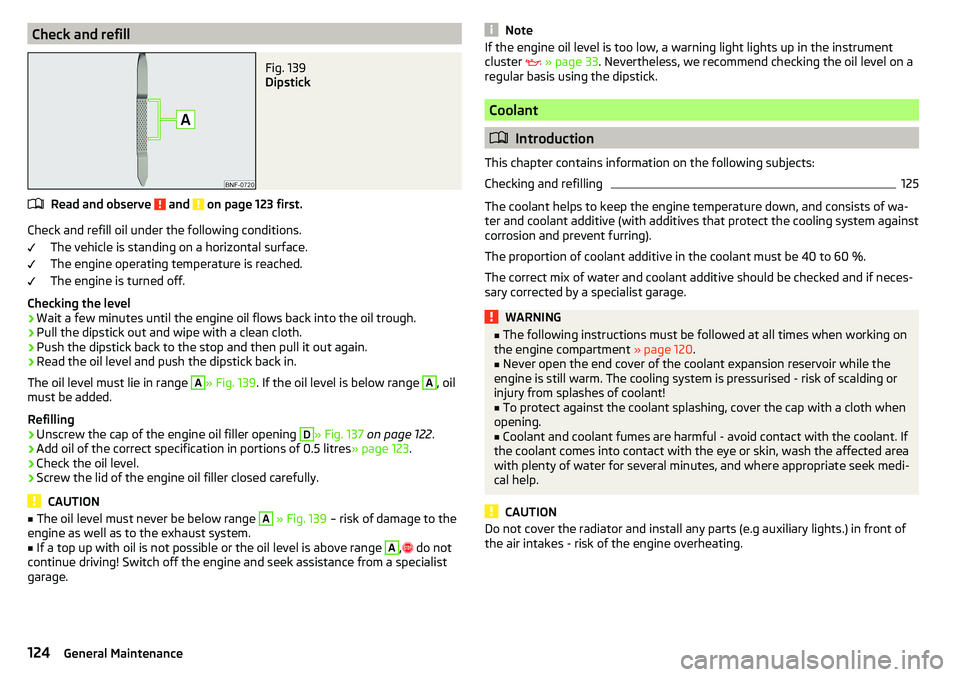
Check and refillFig. 139
Dipstick
Read and observe and on page 123 first.
Check and refill oil under the following conditions.The vehicle is standing on a horizontal surface.
The engine operating temperature is reached.
The engine is turned off.
Checking the level
›
Wait a few minutes until the engine oil flows back into the oil trough.
›
Pull the dipstick out and wipe with a clean cloth.
›
Push the dipstick back to the stop and then pull it out again.
›
Read the oil level and push the dipstick back in.
The oil level must lie in range
A
» Fig. 139 . If the oil level is below range
A
, oil
must be added.
Refilling
›
Unscrew the cap of the engine oil filler opening
D
» Fig. 137 on page 122 .
›
Add oil of the correct specification in portions of 0.5 litres
» page 123.
›
Check the oil level.
›
Screw the lid of the engine oil filler closed carefully.
CAUTION
■
The oil level must never be below range A » Fig. 139 – risk of damage to the
engine as well as to the exhaust system.■
If a top up with oil is not possible or the oil level is above range
A
,
do not
continue driving! Switch off the engine and seek assistance from a specialist
garage.
NoteIf the engine oil level is too low, a warning light lights up in the instrument
cluster » page 33 . Nevertheless, we recommend checking the oil level on a
regular basis using the dipstick.
Coolant
Introduction
This chapter contains information on the following subjects:
Checking and refilling
125
The coolant helps to keep the engine temperature down, and consists of wa-
ter and coolant additive (with additives that protect the cooling system against
corrosion and prevent furring).
The proportion of coolant additive in the coolant must be 40 to 60 %.
The correct mix of water and coolant additive should be checked and if neces-
sary corrected by a specialist garage.
WARNING■ The following instructions must be followed at all times when working on
the engine compartment » page 120.■
Never open the end cover of the coolant expansion reservoir while the
engine is still warm. The cooling system is pressurised - risk of scalding or
injury from splashes of coolant!
■
To protect against the coolant splashing, cover the cap with a cloth when
opening.
■
Coolant and coolant fumes are harmful - avoid contact with the coolant. If
the coolant comes into contact with the eye or skin, wash the affected area
with plenty of water for several minutes, and where appropriate seek medi-
cal help.
CAUTION
Do not cover the radiator and install any parts (e.g auxiliary lights.) in front of
the air intakes - risk of the engine overheating.124General Maintenance
Page 128 of 172
Specification - The brake fluid must comply with the standard VW 501 14 (this
standard meets the requirements of FMVSS 116 DOT4).WARNING■ The following instructions must be followed at all times when working on
the engine compartment » page 120.■
If the fluid level drops significantly within a short time or if it drops below
the “MIN” » Fig. 141mark, this may be an indication of a leak in the brake
system.
Stop driving - There is a risk of an accident! Seek help from a
specialist garage.
Note
■ The brake fluid is changed as part of a compulsory inspection service.■A low brake fluid level is indicated by the warning light in the instrument
cluster » page 32 ,
Braking system . We still recommend inspecting the brake
fluid level in the reservoir from time to time.
Vehicle battery
Introduction
This chapter contains information on the following subjects:
Checking the battery condition
127
Charging
127
Disconnect/reconnect and change
127
The vehicle battery represents a power source for the motor to start and for
the supply of electrical consumers in the car.
Automatic shutdown of consumers - vehicle battery discharge protection
The on-board power supply system tries to prevent the vehicle battery from
discharging in the following ways when it is subject to heavy loading. ▶ By increasing the engine idle speed.
▶ Through the power limitation of certain consumers.
▶ By switching off some consumers (heated seats, heated rear window) for as
long as necessary.
Warning symbols on the vehicle batterySymbolImportanceAlways wear eye protection.Battery acid is severely caustic. Always wear gloves and eye pro-
tection.Keep fire, sparks, open flames and lit cigarettes well clear of the
vehicle battery.When charging the vehicle battery, a highly explosive gas mixture
is produced.Keep children away from the vehicle battery.WARNINGBattery acid is highly corrosive - it can cause injury, chemical burns or poi-
soning! Corrosive vapours in the air irritate and damage the respiratory
tract and the eyes. The following guidelines must be observed.■
Always wear protective gloves, eye and skin protection when handling
the vehicle battery.
■
If your eyes or skin come into contact with the electrolytic fluid, immedi-
ately wash the affected area for a few minutes with a lot of water. Get
medical assistance without delay.
■
Keep the vehicle battery away from people who are not completely inde-
pendent (e.g. children).
■
Do not tilt the battery otherwise battery electrolyte may flow out of the
battery vent openings.
WARNINGWorking on the car battery may cause explosion, fire, injury or chemical
burn! The following guidelines must be observed.■
Do not smoke, use open flames or light or transmitting devices.
■
A discharged vehicle battery may freeze slightly. Never charge up a fro-
zen or thawed vehicle battery. Replace a frozen vehicle battery.
■
Never use a damaged vehicle battery.
■
Do not connect the battery terminals, bridging the two poles will cause a
short circuit.
126General Maintenance
Page 129 of 172
CAUTIONEnsure that battery acid does not come into contact with the bodywork – risk
of damage to the paintwork.
Note
■ We recommend having all work on the vehicle battery carried out by a spe-
cialist garage.■
You should replace batteries older than 5 years.
Checking the battery condition
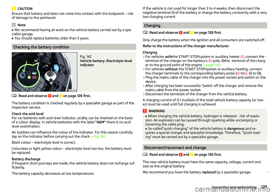
Fig. 142
Vehicle battery: Electrolyte level
indicator
Read and observe and on page 126 first.
The battery condition is checked regularly by a specialist garage as part of the inspection service.
Check the acid level
For car batteries with acid level indicator, acidity can be checked on the basis
of a colour display. In vehicle batteries with the label “AGM” there is no acid
level examination.
Air bubbles can influence the colour of the indicator. For this reason carefully
tap on the indicator before carrying out the check » Fig. 142.
Black colour – electrolyte level is correct.
Colourless or light yellow colour – electrolyte level too low, the battery must
be replaced.
Battery discharge
If frequent short journeys are made, the vehicle battery does not recharge suf-
ficiently.
The battery capacity decreases at low temperatures.
If the vehicle is not used for longer than 3 to 4 weeks, then disconnect the
negative terminal of the battery or charge the battery constantly with a very
low charging current.
Charging
Read and observe
and on page 126 first.
Only charge the battery when the ignition and all consumers are switched off.Refer to the instructions of the charger manufacturer.
Charging
›
For vehicles withthe START-STOPsystem or auxiliary heater
, connect the -
terminal of the charger on the battery’s -pole,
the -terminal of the charg-
er to the ground point of the engine » page 140.
›
For vehicles
without the START-STOPsystem or auxiliary heating, connect
the charger terminals to the corresponding battery poles ( to
,
to
).
›
Plug the mains cable of the charger into the power socket and switch on the
device.
›
After charging has been successful: Switch off the charger and remove the
mains cable from the power socket.
›
Disconnect the terminals of the charger from the vehicle battery.
A charging current of 0.1 multiple of the total vehicle battery capacity (or low-
er) must be used until full charging is achieved.
WARNING■ When charging the vehicle battery, hydrogen is released - risk of explo-
sion. An explosion can be caused through sparking while unclamping or
loosening the cable plug.■
So-called“quick-charging” of the vehicle battery is dangerous and re-
quires a special charger and specialist knowledge. Therefore, “Quick load-
ing” must be carried out by a specialist garage.
Disconnect/reconnect and change
Read and observe
and on page 126 first.
The new vehicle battery must have the same capacity, voltage, current and
size as the original battery.
We recommend you have the battery replaced by a specialist garage.
127Inspecting and replenishing
Page 147 of 172
Note■We recommend always carrying replacement fuses in the vehicle.■There can be several power consuming devices for one fuse. Multiple fuses
may exist for a single power consuming device.
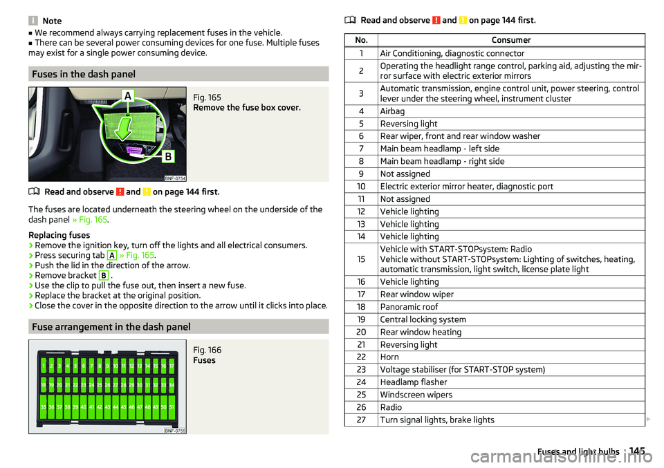
Fuses in the dash panel
Fig. 165
Remove the fuse box cover.
Read and observe and on page 144 first.
The fuses are located underneath the steering wheel on the underside of the
dash panel » Fig. 165.
Replacing fuses
›
Remove the ignition key, turn off the lights and all electrical consumers.
›
Press securing tab
A
» Fig. 165 .
›
Push the lid in the direction of the arrow.
›
Remove bracket
B
.
›
Use the clip to pull the fuse out, then insert a new fuse.
›
Replace the bracket at the original position.
›
Close the cover in the opposite direction to the arrow until it clicks into place.
Fuse arrangement in the dash panel
Fig. 166
Fuses
Read and observe and on page 144 first.No.Consumer1Air Conditioning, diagnostic connector2Operating the headlight range control, parking aid, adjusting the mir-
ror surface with electric exterior mirrors3Automatic transmission, engine control unit, power steering, control
lever under the steering wheel, instrument cluster4Airbag5Reversing light6Rear wiper, front and rear window washer7Main beam headlamp - left side8Main beam headlamp - right side9Not assigned10Electric exterior mirror heater, diagnostic port11Not assigned12Vehicle lighting13Vehicle lighting14Vehicle lighting15Vehicle with START-STOPsystem: Radio
Vehicle without START-STOPsystem: Lighting of switches, heating,
automatic transmission, light switch, license plate light16Vehicle lighting17Rear window wiper18Panoramic roof19Central locking system20Rear window heating21Reversing light22Horn23Voltage stabiliser (for START-STOP system)24Headlamp flasher25Windscreen wipers26Radio27Turn signal lights, brake lights 145Fuses and light bulbs
Page 148 of 172
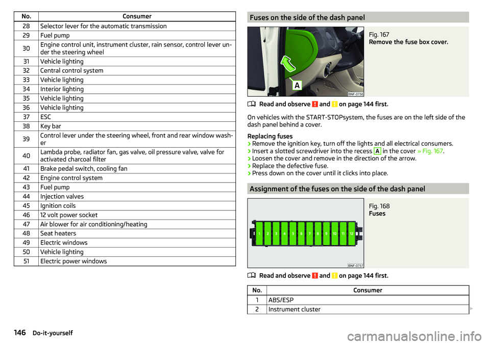
No.Consumer28Selector lever for the automatic transmission29Fuel pump30Engine control unit, instrument cluster, rain sensor, control lever un-
der the steering wheel31Vehicle lighting32Central control system33Vehicle lighting34Interior lighting35Vehicle lighting36Vehicle lighting37ESC38Key bar39Control lever under the steering wheel, front and rear window wash- er40Lambda probe, radiator fan, gas valve, oil pressure valve, valve for
activated charcoal filter41Brake pedal switch, cooling fan42Engine control system43Fuel pump44Injection valves45Ignition coils4612 volt power socket47Air blower for air conditioning/heating48Seat heaters49Electric windows50Vehicle lighting51Electric power windowsFuses on the side of the dash panelFig. 167
Remove the fuse box cover.
Read and observe and on page 144 first.
On vehicles with the START-STOPsystem, the fuses are on the left side of the
dash panel behind a cover.
Replacing fuses
›
Remove the ignition key, turn off the lights and all electrical consumers.
›
Insert a slotted screwdriver into the recess
A
in the cover » Fig. 167.
›
Loosen the cover and remove in the direction of the arrow.
›
Replace the defective fuse.
›
Press down on the cover until it clicks into place.
Assignment of the fuses on the side of the dash panel
Fig. 168
Fuses
Read and observe and on page 144 first.
No.Consumer1ABS/ESP2Instrument cluster 146Do-it-yourself
Page 149 of 172
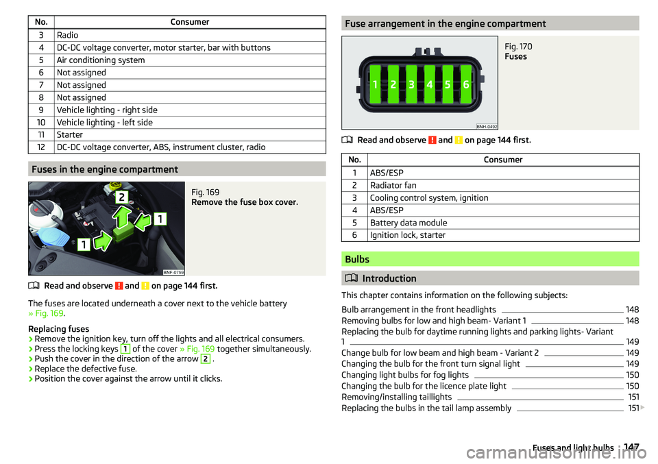
No.Consumer3Radio4DC-DC voltage converter, motor starter, bar with buttons5Air conditioning system6Not assigned7Not assigned8Not assigned9Vehicle lighting - right side10Vehicle lighting - left side11Starter12DC-DC voltage converter, ABS, instrument cluster, radio
Fuses in the engine compartment
Fig. 169
Remove the fuse box cover.
Read and observe and on page 144 first.
The fuses are located underneath a cover next to the vehicle battery
» Fig. 169 .
Replacing fuses
›
Remove the ignition key, turn off the lights and all electrical consumers.
›
Press the locking keys
1
of the cover » Fig. 169 together simultaneously.
›
Push the cover in the direction of the arrow
2
.
›
Replace the defective fuse.
›
Position the cover against the arrow until it clicks.
Fuse arrangement in the engine compartmentFig. 170
Fuses
Read and observe and on page 144 first.
No.Consumer1ABS/ESP2Radiator fan3Cooling control system, ignition4ABS/ESP5Battery data module6Ignition lock, starter
Bulbs
Introduction
This chapter contains information on the following subjects:
Bulb arrangement in the front headlights
148
Removing bulbs for low and high beam- Variant 1
148
Replacing the bulb for daytime running lights and parking lights- Variant
1
149
Change bulb for low beam and high beam - Variant 2
149
Changing the bulb for the front turn signal light
149
Changing light bulbs for fog lights
150
Changing the bulb for the licence plate light
150
Removing/installing taillights
151
Replacing the bulbs in the tail lamp assembly
151
147Fuses and light bulbs
Page 154 of 172
Technical data
Technical data
Basic vehicle data
Introduction
This chapter contains information on the following subjects:
Vehicle data
152
Operating weight
153
Payload
153
Measurement of fuel consumption and CO 2 emissions according to ECE
Regulations and EU Directives
153
Dimensions
154
Departure angle
155
The details given in the vehicle's technical documentation always take prece-
dence over the details in the Owner's Manual.
The performance values listed were determined without performance-reduc- ing equipment, e.g. air conditioning system.
The values given have been determined in accordance with regulations and in
conditions prescribed by legal or technical provisions for determining the oper-
ating and technical data of vehicles.
The listed values are for the basic model without optional equipment.
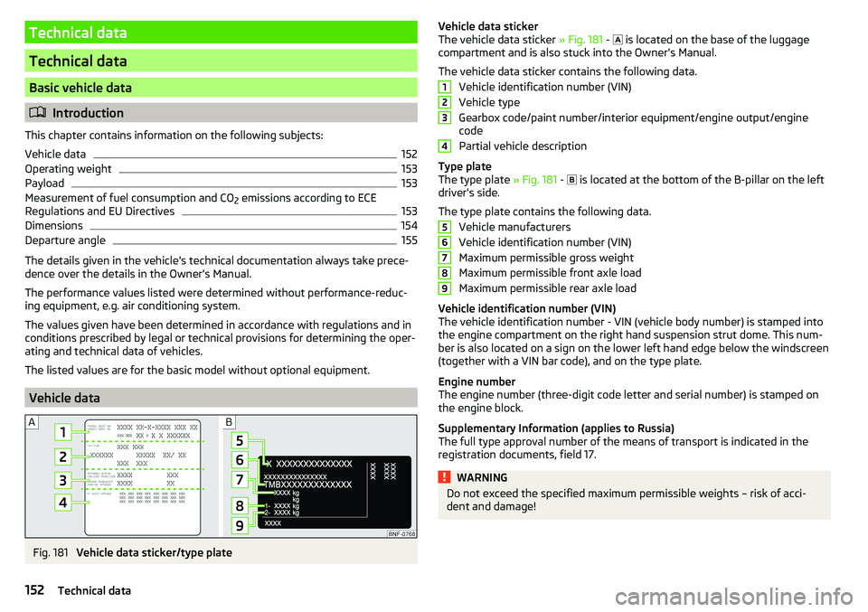
Vehicle data
Fig. 181
Vehicle data sticker/type plate
Vehicle data sticker
The vehicle data sticker » Fig. 181 - is located on the base of the luggage
compartment and is also stuck into the Owner's Manual.
The vehicle data sticker contains the following data. Vehicle identification number (VIN)
Vehicle type
Gearbox code/paint number/interior equipment/engine output/engine code
Partial vehicle description
Type plate
The type plate » Fig. 181 -
is located at the bottom of the B-pillar on the left
driver's side.
The type plate contains the following data. Vehicle manufacturers
Vehicle identification number (VIN)
Maximum permissible gross weight
Maximum permissible front axle load
Maximum permissible rear axle load
Vehicle identification number (VIN)
The vehicle identification number - VIN (vehicle body number) is stamped into
the engine compartment on the right hand suspension strut dome. This num-
ber is also located on a sign on the lower left hand edge below the windscreen
(together with a VIN bar code), and on the type plate.
Engine number
The engine number (three-digit code letter and serial number) is stamped on the engine block.
Supplementary Information (applies to Russia)
The full type approval number of the means of transport is indicated in the
registration documents, field 17.WARNINGDo not exceed the specified maximum permissible weights – risk of acci-
dent and damage!123456789152Technical data
Page 155 of 172
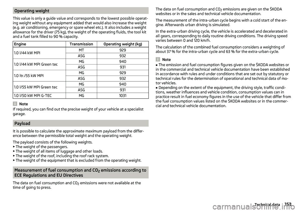
Operating weight
This value is only a guide value and corresponds to the lowest possible operat-
ing weight without any equipment added that would also increase the weight
(e.g. air conditioning, emergency or spare wheel etc.). It also includes a weight
allowance for the driver (75 kg), the weight of the operating fluids, the tool kit
and a fuel tank filled to 90 % capacity.EngineTransmissionOperating weight (kg)1.0 l/44 kW MPIMT929ASG9321.0 l/44 kW MPI Green tecMG940ASG9311.0 ltr./55 kW MPIMG929ASG9321.0 l/55 kW MPI Green tecMG940ASG9311.0 l/50 kW MPI G-TECMG1031
Note
If required, you can find out the precise weight of your vehicle at a specialist
garage.
Payload
It is possible to calculate the approximate maximum payload from the differ-
ence between the permissible total weight and the operating weight.
The payload consists of the following weights.
▶ The weight of the passengers.
▶ The weight of all items of luggage and other loads.
▶ The weight of the roof, including the roof rack system.
▶ The weight of the equipment that is excluded from the operating weight.
Measurement of fuel consumption and CO
2 emissions according to
ECE Regulations and EU Directives
The data on fuel consumption and CO 2 emissions were not available at the
time of going to press.
The data on fuel consumption and CO 2 emissions are given on the ŠKODA
websites or in the sales and technical vehicle documentation.
The measurement of the intra-urban cycle begins with a cold start of the en-
gine. Afterwards urban driving is simulated.
In the extra-urban driving cycle, the vehicle is accelerated and decelerated in
all gears, corresponding to daily routine driving conditions. The driving speed
varies between 0 and 120 km/h.
The calculation of the combined fuel consumption considers a weighting of
about 37 % for the intra-urban cycle and 63 % for the extra-urban cycle.
Note
■ The emission and fuel consumption figures given on the ŠKODA websites or
in the commercial and technical vehicle documentation have been established
in accordance with rules and under conditions that are set out by statutory or
technical rules for the determination of operational and technical data of mo-
tor vehicles.■
Depending on the extent of the equipment, the driving style, traffic condi-
tions, weather influences and vehicle condition, consumption values can in
practice result in fuel economy figures in the use of the vehicle that differ from
the fuel consumption values listed on the ŠKODA websites or in the commer-
cial and technical vehicle documentation.
153Technical data
Page 159 of 172
Index
A
ABS Operation
104
Warning light34
Acceptance and recycling of used vehicles
112
Accessories110
Adjusting Steering wheel
13
Adjusting the seats12
Adjustment Light range
49
Adjust radio volume77
Advice on tyre/wheel usage128
Air-conditioning system Air outlet vents
74
air bag17
Airbag Adjustments and impairments to the airbagsystem
111
Deactivation20
Deployment18
Warning light35
Airbag system17
air conditioning recirculation
73
Air conditioning71
Climatronic73
Manual air conditioning72
Air outlet vents74
All-year tyres131
Alternator Warning light
32
AM82
Anti-lock braking system (ABS)104
Anti-theft wheel bolts136
Application management93
Connection93
Main menu94
Ashtray62
Assist systems103
Audio source85
Auto check control41
Automated manual transmission Kick-down
101
Tiptronic101
Automated transmission100
Automatically turn off the radio77
Automatic driving light control51
Automatic shutdown of consumers126
Automatic transmission Defect
33
Selector lever100
Starting-off and driving101
Warning light33
Automatic transmission modes100
AUX87
Avoiding damage to your vehicle102
B
Battery Change in key
142
Belts14
Belt tensioners16
Blues radio Device language settings
81
Display settings81
Factory settings81
Media menu84
Media menu settings81
menu settings80
Radio menu81
Radio menu settings80
safe removal of the data source81
Settings80
Sound settings80
Status line77
Blues Radio75
Device description76
Information on the device system81
Blues radio display76
Bluetooth profile93
Bluetooth® player87
Bonnet Closing
122
Opening122
Boot Class N1 vehicles
70
see boot lid46
Boot lid Automatic locking
46
Open/Close46
Brake Assist (HBA)104
Brake booster98
Brake fluid125
Check125
specification125
Brake pads new
98
Brake pedal - automatic transmission warning light
36
Brakes Brake booster
98
Brake fluid125
Braking and stabilisation systems103
Handbrake98
Information on braking98
Warning lights32
Brake system103
Braking Running in
102
Breakdown kit137
Breakdown service90
see Help in an emergency10
157Index