air conditioning SKODA CITIGO 2017 Owners Manual
[x] Cancel search | Manufacturer: SKODA, Model Year: 2017, Model line: CITIGO, Model: SKODA CITIGO 2017Pages: 172, PDF Size: 24.54 MB
Page 5 of 172
Table of Contents
materials defect liability and ŠKODA warranty
for new cars5
Printed Owner's Manual
7
Online Owner's Manual
8
Notes
9
Structure of the Owner's Manual and further
information
10
Abbreviations
Safety
Passive Safety
12
General information
12
Correct and safe seated position
12
Seat belts
14
Using seat belts
14
Inertia reels and belt tensioners
16
Airbag system
17
Description of the airbag system
17
Airbag deactivation
20
Transporting children safely
21
Child seat
21
Fastening systems
24
Using the system
cockpit
29
Overview
28
Instruments and warning lights
30
Instrument cluster
30
Warning lights
31Information system37Driver information system37
Driving data (multifunction display)
39
MAXI DOT display
41
Service interval display
42
Unlocking and opening
42
Unlocking and locking
42
Luggage compartment lid
46
Window operation
46
Panoramic tilt / slide sunroof
48
Lights and visibility
49
Lights
49
Interior lighting
52
Visibility
53
Windscreen wipers and washers
53
Rear view mirror
55
Seats and head restraints
56
Front seats
56
Rear seat backrests
57
Headrests
57
Front seat heating
58
Useful features
59
Interior fittings
59
Phone bracket
66
Transport of cargo
67
Luggage compartment and transporting
objects
67
Transportation on the roof rack
70
Heating and ventilation
71
Heating, manual air conditioning system,
Climatronic
71Infotainment
Swing/ Blues Radio75
Important notes
75
Unit overview and operation
76
Device Settings - Swing
78
Device settings - Blues
80
Radio
81
Media
84
Phone
88
Application operationŠKODA Move & Fun
93
Driving
Starting-off and Driving
95
Starting and stopping the engine
95
START-STOPsystem
96
Brakes and Parking
98
Manual gear changing and pedals
99
Automated transmission
100
Running in and economical driving
101
Avoiding damage to your vehicle
102
Assist systems
103
General information
103
Braking and stabilisation systems
103
Parking aid (ParkPilot)
105
Cruise Control System
106
City Safe Drive
107
Tyre pressure monitoring
108
General Maintenance
Care and maintenance
110
Service work, adjustments and technical
alterations
110
Service intervals
112
Cleaning and care
1133Table of Contents
Page 31 of 172
Using the system
cockpit
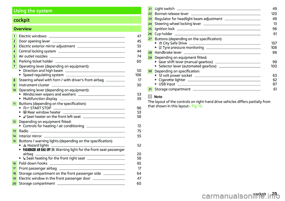
OverviewElectric windows
47
Door opening lever
45
Electric exterior mirror adjustment
55
Central locking system
44
Air outlet nozzles
74
Parking ticket holder
60
Operating lever (depending on equipment):
▶ Direction and high beam
50
▶Speed regulating system
106
Steering wheel with horn / with driver's front airbag
17
Instrument cluster
30
Operating lever (depending on equipment):
▶ Windscreen wipers and washers
53
▶Multifunction display
39
Buttons (depending on the specification):
▶ START STOP
96
▶
Rear window heater
53
▶
Seat heater on the front left seat
58
Depending on equipment fitted:
▶ Controls for heating / air conditioning
72
Radio
75
Interior mirror
55
Buttons / warning lights (depending on the specification):
▶ Hazard lights
52
▶
Warning light for the front seat passenger
airbag
20
▶ Seat heating for the front right seat
58
Fold-down hooks
65
Front passenger airbag
17
Storage compartment on the front passenger side
64
Electric window in the front passenger door
47
Storage compartment
601234567891011121314151617181920Light switch49
Bonnet release lever
120
Regulator for headlight beam adjustment
49
Steering wheel locking lever
13
Ignition lock
96
Cup holder
61
Buttons (depending on the specification):
▶ City Safe Drive
107
▶
Tyre pressure monitoring
108
Handbrake lever
98
Depending on equipment fitted:
▶ Gear shift lever (manual gearbox)
99
▶Selector lever (automated gearbox)
100
Depending on specification:
▶ 12 volt power socket
63
▶Cigarette lighter
62
▶USB input
87
Storage compartment
61
Note
The layout of the controls on right-hand drive vehicles differs partially from
that shown in this layout » Fig. 15.212223242526272829303129cockpit
Page 73 of 172
WARNING (Continued)■When transporting heavy objects or objects which take up a large area on
the roof rack system, the handling of the car may change as a result of the
displacement of the centre of gravity. The style of driving and speed must
therefore be adapted to the current circumstances.■
The permissible roof load, permissible axle loads and permissible total ve-
hicle weight must not be exceeded under any circumstances – risk of acci-
dent!
CAUTION
■ Make sure that the panoramic tilt / slide sunroof or the boot lid does not col-
lide with the roof load when opened.■
Ensure the roof aerial is not impaired by the load being transported.
Note
We recommend that you use a roof rack from ŠKODA Original Accessories.Heating and ventilation
Heating, manual air conditioning system, Climatronic
Introduction
This chapter contains information on the following subjects:
Heating and manual air conditioning
72
Climatronic (automatic air conditioning)
73
Climatronic - automatic operation
73
recirculation
73
Air outlet vents
74
The heater heats and ventilates the vehicle interior. The air conditioning sys-
tem also cools and dehumidifies the vehicle interior.
The heating effect is dependent upon the coolant temperature, thus full heat
output only occurs when the engine has reached its operating temperature.
The cooling system works under the following conditions. The cooling system is switched on.
The engine is running.
The outside temperature is above 2 °C.
The blower is switched on.
When the cooling system is switched on, it prevents misting of the windscreen
and windows.
It is possible to boost the effectiveness of the cooling system by briefly acti-
vating the air recirculation system » page 73.
Health protection
To reduce health risks (e.g. common colds), the following instructions for the
use of the cooling system are to be observed. ▶ The difference between the outside temperature and the inside temperature
should not be greater than 5 °C.
▶ The cooling system should be turned off about 10 minutes before the end of
the journey.
▶ Once a year, a disinfection of the air conditioner is to be carried out by a spe-
cialist company.
71Heating and ventilation
Page 74 of 172
WARNING■The blower should always be on to prevent the windows from misting.
Otherwise there is a risk of accident.■
Under certain circumstances, air at a temperature of about 5 °C can flow
out of the vents when the cooling system is switched on.
Note
■ The air inlet in front of the windscreen must be free of e.g. ice, snow or
leaves to ensure that the heating and cooling system operates properly.■
After switching on the cooling Condensation from the evaporator of the air
conditioning may drip down and form a puddle below the vehicle. This is not a
leak!
■
If the coolant temperature is too high, the cooling system is switched off to
ensure that the engine cools down.
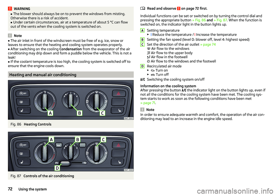
Heating and manual air conditioning
Fig. 86
Heating Controls
Fig. 87
Controls of the air conditioning
Read and observe on page 72 first.
Individual functions can be set or switched on by turning the control dial and
pressing the appropriate button » Fig. 86 and » Fig. 87 . When the function is
switched on, the indicator light in the button lights up.
Setting temperature▶ Reduce the temperature /
Increase the temperature
Setting the fan speed (level 0: blower off, level 4: highest speed)
Set the direction of the air outlet » page 74
Air flow to the windows
Air flow to the upper body
Air flow in the footwell
Air flow to the windows and the footwell
Recirculated air mode
▶ Turn on
▶ Turn off
Switching the cooling system on/off
Information on the cooling system
After pressing the button the indicator light on the button lights up, even if
not all the conditions for the cooling system have been met. The cooling sys-
tem starts to work as soon as the following conditions have been met
» page 71 .
Note
In order to ensure adequate warmth and comfort, the operation of the air con-
ditioning may lead to an increase in the engine idle speed.ABCD72Using the system
Page 75 of 172
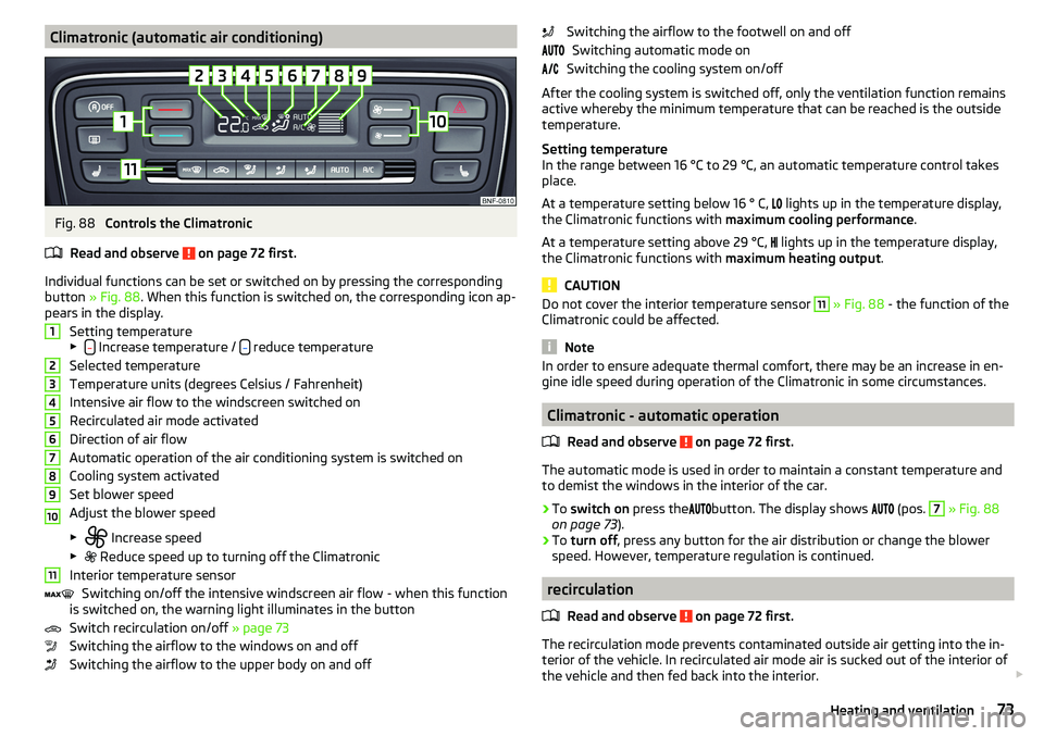
Climatronic (automatic air conditioning)Fig. 88
Controls the Climatronic
Read and observe
on page 72 first.
Individual functions can be set or switched on by pressing the corresponding
button » Fig. 88 . When this function is switched on, the corresponding icon ap-
pears in the display.
Setting temperature
▶
Increase temperature / reduce temperature
Selected temperature
Temperature units (degrees Celsius / Fahrenheit)
Intensive air flow to the windscreen switched on
Recirculated air mode activated
Direction of air flow
Automatic operation of the air conditioning system is switched on
Cooling system activated
Set blower speed
Adjust the blower speed
▶ Increase speed
▶ Reduce speed up to turning off the Climatronic
Interior temperature sensor Switching on/off the intensive windscreen air flow - when this function
is switched on, the warning light illuminates in the button
Switch recirculation on/off » page 73
Switching the airflow to the windows on and off
Switching the airflow to the upper body on and off
1234567891011Switching the airflow to the footwell on and off Switching automatic mode on
Switching the cooling system on/off
After the cooling system is switched off, only the ventilation function remains
active whereby the minimum temperature that can be reached is the outside
temperature.
Setting temperature
In the range between 16 °C to 29 °C, an automatic temperature control takes
place.
At a temperature setting below 16 ° C,
lights up in the temperature display,
the Climatronic functions with maximum cooling performance .
At a temperature setting above 29 °C, lights up in the temperature display,
the Climatronic functions with maximum heating output.
CAUTION
Do not cover the interior temperature sensor 11 » Fig. 88 - the function of the
Climatronic could be affected.
Note
In order to ensure adequate thermal comfort, there may be an increase in en-
gine idle speed during operation of the Climatronic in some circumstances.
Climatronic - automatic operation
Read and observe
on page 72 first.
The automatic mode is used in order to maintain a constant temperature and
to demist the windows in the interior of the car.
›
To switch on press the
button. The display shows
(pos.
7
» Fig. 88
on page 73 ).
›
To turn off , press any button for the air distribution or change the blower
speed. However, temperature regulation is continued.
recirculation
Read and observe
on page 72 first.
The recirculation mode prevents contaminated outside air getting into the in-
terior of the vehicle. In recirculated air mode air is sucked out of the interior of
the vehicle and then fed back into the interior.
73Heating and ventilation
Page 76 of 172
›To the
turn on move the slider D into position or press the button in
Climatronic.›
To Turn off move the slider
D
into position
or press the button
in Cli-
matronic.
WARNINGThe recirculation system cannot be switched on for a longer period of time,
because no fresh air is fed through from the outside. “Stale air” may result
in fatigue in the driver and occupants, reduce attention levels and also
cause the windows to mist up. As soon as windows mist up, turn on the re-
circulation system immediately - risk of accident!
CAUTION
We recommend not smoking in the vehicle when the recirculating air operation
is switched on. The smoke sucked from the interior is deposited on the evapo-
rator of the air conditioner. This produces a permanent odour when the air
conditioning system is operating which can only be eliminated through consid-
erable effort and expense (replacement of compressor).
Air outlet vents
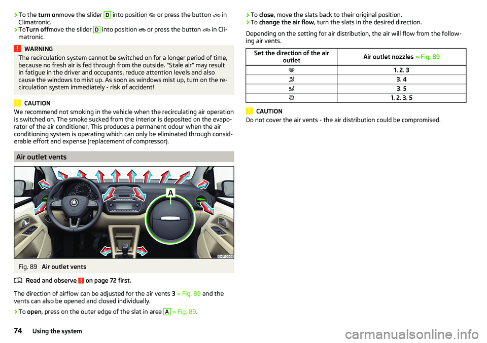
Fig. 89
Air outlet vents
Read and observe
on page 72 first.
The direction of airflow can be adjusted for the air vents 3 » Fig. 89 and the
vents can also be opened and closed individually.
›
To open , press on the outer edge of the slat in area
A
» Fig. 89 .
›To
close , move the slats back to their original position.›To change the air flow , turn the slats in the desired direction.
Depending on the setting for air distribution, the air will flow from the follow-
ing air vents.Set the direction of the air outletAir outlet nozzles » Fig. 891. 2 . 33 . 43 . 51. 2 . 3 . 5
CAUTION
Do not cover the air vents - the air distribution could be compromised.74Using the system
Page 99 of 172
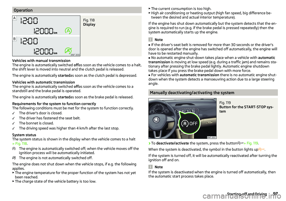
OperationFig. 118
Display
Vehicles with manual transmission
The engine is automatically switched offas soon as the vehicle comes to a halt,
the shift lever is moved into neutral and the clutch pedal is released.
The engine is automatically startedas soon as the clutch pedal is depressed.
Vehicles with automatic transmission
The engine is automatically switched offas soon as the vehicle comes to a
standstill and the brake pedal is operated.
The engine is automatically startedas soon as the brake pedal is released.
Requirements for the system to function correctly
The following conditions must be met for the system to function correctly.
The driver's door is closed.
The driver has fastened the seat belt.
The bonnet is closed.
The driving speed was higher than 4 km/h after the last stop.
System status
The system status is shown in the display when the vehicle comes to a halt
» Fig. 118 .
The engine is automatically switched off; when the vehicle moves off the
ignition process will be automatically initiated.
The engine is not automatically switched off.
The engine does not shut down when the vehicle stops, if e.g. the following
applies.
▶ The engine temperature for the proper function of the system has not yet
been reached.
▶ The charge state of the vehicle battery is too low.
▶
The current consumption is too high.
▶ High air conditioning or heating output (high fan speed, big difference be-
tween the desired and actual interior temperature).
If the engine has shut down automatically but the system detects that the en-
gine is required to run (e.g. if the brake pedal is pressed repeatedly) then the
system automatically starts up the engine.
Note
■ If the driver's seat belt is removed for more than 30 seconds or the driver's
door is opened after the engine has switched off automatically, the engine will
have to be restarted manually.■
No automatic engine shut-down takes place when a vehicle with automatic
transmission is moving at low speed (e.g. during a traffic jam) and remains sta-
tionary after pressing the brake pedal lightly. Automatic engine shutdown
takes place if you press the brake pedal down with more force.
■
For vehicles with automatic transmission there is no automatic engine shut-
down when the system detects a manoeuvring action due to a large steering
angle.
Manually deactivating/activating the system
Fig. 119
Button for the START-STOP sys-
tem
›
To deactivate/activate the system, press the button
» Fig. 119 .
When the system is deactivated, the symbol in the button lights up
.
If the system is turned off, it will be automatically reactivated after turning the
ignition off and on.
Note
If the system is deactivated when the engine is turned off automatically, then
the automatic start process takes place.97Starting-off and Driving
Page 147 of 172
Note■We recommend always carrying replacement fuses in the vehicle.■There can be several power consuming devices for one fuse. Multiple fuses
may exist for a single power consuming device.
Fuses in the dash panel
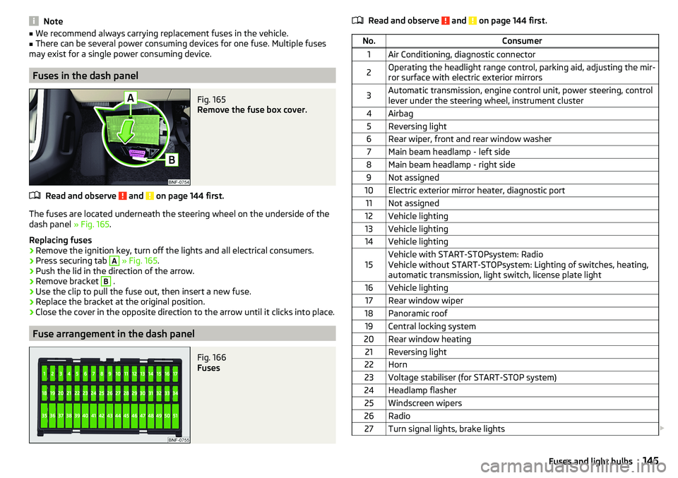
Fig. 165
Remove the fuse box cover.
Read and observe and on page 144 first.
The fuses are located underneath the steering wheel on the underside of the
dash panel » Fig. 165.
Replacing fuses
›
Remove the ignition key, turn off the lights and all electrical consumers.
›
Press securing tab
A
» Fig. 165 .
›
Push the lid in the direction of the arrow.
›
Remove bracket
B
.
›
Use the clip to pull the fuse out, then insert a new fuse.
›
Replace the bracket at the original position.
›
Close the cover in the opposite direction to the arrow until it clicks into place.
Fuse arrangement in the dash panel
Fig. 166
Fuses
Read and observe and on page 144 first.No.Consumer1Air Conditioning, diagnostic connector2Operating the headlight range control, parking aid, adjusting the mir-
ror surface with electric exterior mirrors3Automatic transmission, engine control unit, power steering, control
lever under the steering wheel, instrument cluster4Airbag5Reversing light6Rear wiper, front and rear window washer7Main beam headlamp - left side8Main beam headlamp - right side9Not assigned10Electric exterior mirror heater, diagnostic port11Not assigned12Vehicle lighting13Vehicle lighting14Vehicle lighting15Vehicle with START-STOPsystem: Radio
Vehicle without START-STOPsystem: Lighting of switches, heating,
automatic transmission, light switch, license plate light16Vehicle lighting17Rear window wiper18Panoramic roof19Central locking system20Rear window heating21Reversing light22Horn23Voltage stabiliser (for START-STOP system)24Headlamp flasher25Windscreen wipers26Radio27Turn signal lights, brake lights 145Fuses and light bulbs
Page 148 of 172
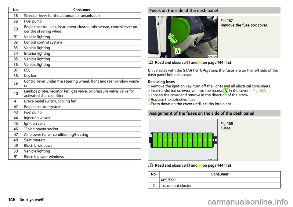
No.Consumer28Selector lever for the automatic transmission29Fuel pump30Engine control unit, instrument cluster, rain sensor, control lever un-
der the steering wheel31Vehicle lighting32Central control system33Vehicle lighting34Interior lighting35Vehicle lighting36Vehicle lighting37ESC38Key bar39Control lever under the steering wheel, front and rear window wash- er40Lambda probe, radiator fan, gas valve, oil pressure valve, valve for
activated charcoal filter41Brake pedal switch, cooling fan42Engine control system43Fuel pump44Injection valves45Ignition coils4612 volt power socket47Air blower for air conditioning/heating48Seat heaters49Electric windows50Vehicle lighting51Electric power windowsFuses on the side of the dash panelFig. 167
Remove the fuse box cover.
Read and observe and on page 144 first.
On vehicles with the START-STOPsystem, the fuses are on the left side of the
dash panel behind a cover.
Replacing fuses
›
Remove the ignition key, turn off the lights and all electrical consumers.
›
Insert a slotted screwdriver into the recess
A
in the cover » Fig. 167.
›
Loosen the cover and remove in the direction of the arrow.
›
Replace the defective fuse.
›
Press down on the cover until it clicks into place.
Assignment of the fuses on the side of the dash panel
Fig. 168
Fuses
Read and observe and on page 144 first.
No.Consumer1ABS/ESP2Instrument cluster 146Do-it-yourself
Page 149 of 172
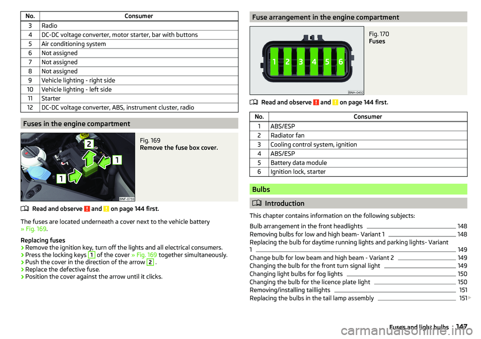
No.Consumer3Radio4DC-DC voltage converter, motor starter, bar with buttons5Air conditioning system6Not assigned7Not assigned8Not assigned9Vehicle lighting - right side10Vehicle lighting - left side11Starter12DC-DC voltage converter, ABS, instrument cluster, radio
Fuses in the engine compartment
Fig. 169
Remove the fuse box cover.
Read and observe and on page 144 first.
The fuses are located underneath a cover next to the vehicle battery
» Fig. 169 .
Replacing fuses
›
Remove the ignition key, turn off the lights and all electrical consumers.
›
Press the locking keys
1
of the cover » Fig. 169 together simultaneously.
›
Push the cover in the direction of the arrow
2
.
›
Replace the defective fuse.
›
Position the cover against the arrow until it clicks.
Fuse arrangement in the engine compartmentFig. 170
Fuses
Read and observe and on page 144 first.
No.Consumer1ABS/ESP2Radiator fan3Cooling control system, ignition4ABS/ESP5Battery data module6Ignition lock, starter
Bulbs
Introduction
This chapter contains information on the following subjects:
Bulb arrangement in the front headlights
148
Removing bulbs for low and high beam- Variant 1
148
Replacing the bulb for daytime running lights and parking lights- Variant
1
149
Change bulb for low beam and high beam - Variant 2
149
Changing the bulb for the front turn signal light
149
Changing light bulbs for fog lights
150
Changing the bulb for the licence plate light
150
Removing/installing taillights
151
Replacing the bulbs in the tail lamp assembly
151
147Fuses and light bulbs