key SKODA FABIA 2000 1.G / 6Y User Guide
[x] Cancel search | Manufacturer: SKODA, Model Year: 2000, Model line: FABIA, Model: SKODA FABIA 2000 1.G / 6YPages: 86, PDF Size: 3.58 MB
Page 62 of 86

Downloaded from www.Manualslib.com manuals search engine FABIA 2000➤Inspection and Maintenance
Electrical SystemEdition 09.04
S00.5301.14.2002-6 page 8 02
Resetting service interval display (SID) with
-V.A.G 1552- (QG1, QG2)
–Connect -V.A.G 1552-.
–Switch on ignition.
–Enter address word 17 „Dash Panel Insert“ and con-
firm with .
Readout on display (e.g.):
–Note the dash panel insert coding.
–Press key.
Readout on display (e.g.):
–Press key.
Readout on display:
–Enter address word 10 „Adaptation“ and confirm with
the key.
Readout on display:
–Enter adjustment channel 02.
Readout on display:
–Press .
Readout on display:
–Enter adaptation value 00000.
Readout on display:
–Confirm the entry with key .
Read-out on display after entering adaptation value
00000:
–Confirm the entry with key .
Readout on display:
–Confirm the entry with key .
Readout on display:
–Press key.
Readout on display:
–Enter 06 for „End output“.
Readout on display:
–Confirm the entry with key .
–Switch off ignition.
Resetting service interval display (SID) without
-V.A.G 1552- (QG1, QG2)
–Switch off ignition.
Q
6Y1919870B COMBIINSTRUMENT VDO X09 ->
Coding 03111 WSC 12345
TMBMC46Y0Y7000001 SKZ7Z0W0204038 ->
Vehicle system test HELP
Select function XX
Q
Adjustment
Enter channel number XX
Channel 2 Adaptation 1
- -
Channel 2 Adaptation 1
Enter adjustment value XXXXX
Channel 2 adjustment 1 Q
Enter adaptation value 00000
Q
Channel 2 adjustment 0 Q
- -
Q
Channel 2 adjustment 0 Q
Store changed value?
Q
Channel 2 Adaptation 0
Changed value stored
Vehicle system test HELP
Select function XX
Vehicle system test HELP
06 - End output
Q
Page 64 of 86

Downloaded from www.Manualslib.com manuals search engine FABIA 2000➤Inspection and Maintenance
Electrical SystemEdition 09.04
S00.5301.14.2002-6 page 10 02
–Connect -V.A.G 1552-.
–Switch on ignition.
–Enter address word 17 „Dash Panel Insert“ and con-
firm with .
Readout on display (e.g.):
–Note the dash panel insert coding.
–Press key.
Readout on display (e.g.):
–Press key.
Readout on display:
–Enter function 07 „Code control unit“ and confirm with
key.
Readout on display:
–Enter dash panel insert coding which is identical to the
original coding. The value on the fourth position must,
however, be altered from 1 to 2.
XXX1X - QG1
XXX2X - QG2
Readout on display (e.g.):
–Confirm the entry with key .
Readout on display (e.g.):
–Press key.
Readout on display (e.g.):
–Press key.
Readout on display:
–Enter 06 for „End output“.
Readout on display:
–Confirm the entry with key .
–Switch off ignition.
–Switch off -V.A.G 1552-.
Inspecting headlight beam setting and
adjusting if necessary
Special tools, test and measuring equipment and
auxiliary items required
♦Headlight beam setting device
In principle the following inspection and setting descrip-
tion applies for all countries. However, comply with na-
tional guidelines and legislation of the relevant country.
⇒Operating instructions for the headlight beam setting
device
Q
6Y1919870B COMBIINSTRUMENT VDO X09 ->
Coding 03111 WSC 12345
TMBMC46Y0Y7000001 SKZ7Z0W0204038 ->
Vehicle system test HELP
Select function XX
Q
Coding control unit
Enter code number XXXXX (0-32767)
Coding control unit
Enter code number 03121 (0-32767)
Q
6Y1919870B COMBIINSTRUMENT VDO X09 ->
Coding 03121 WSC 12345
TMBMC46Y0Y7000001 SKZ7Z0W0204038 ->
Vehicle system test HELP
Select function XX
Vehicle system test HELP
06 End output
Q
Page 70 of 86

Downloaded from www.Manualslib.com manuals search engine FABIA 2000➤Inspection and Maintenance
BodyEdition 09.04
S00.5301.14.2002-7 page 2 02
Do not affix any stickers or cover over the padded boss of
the steering wheel -1- and the foam-lined surface of the
airbag unit on the front passenger side -2- or do not carry
out any modifications to these parts. These parts must
only be cleaned with a dry and slightly moistened cloth.
Inspect key switch for deactivation of
front passenger airbag
–Switch off ignition.
–Turn the key switch for deactivation of front passenger
airbag to the position „OFF“.
When the ignition is switched on the airbag warning lamp
must light up in the front interior light.
–Switch off ignition.
–Turn the key switch for deactivation of front passenger
airbag to the position „ON“.
After the ignition and the front passenger airbag is
switched on, the airbag warning light in the front interior
light must no longer light up after approx. 3 seconds.
Key switch for deactivation of front passenger airbag
must only be turned when ignition is switched off. If the
position of the switch is changed, the airbag control unit
can evaluate a fault; the individual contacts in the switch
make contact during different time intervals and subse-
quently the warning lamp lights up in the dash panel in-
sert (there is no risk of airbag activation).
Check underbody protection and body
paintwork for damage
The inspection of the underbody sealant and paintwork
should cover the following points:
1) undamaged layer of PVC Plastisol
–Vehicle floor
–Wings and wheel housings
–Sills
2) undamaged paintwork
–all body joints
–surround of windscreen
–surround of rear window
–flange of inner surfaces of engine hood
–horizontal and vertical painted surfaces
–Connection of the roof in the area of the luggage com-
partment lid
It is essential to rectify any defects found!
Note
Note
Page 73 of 86

Downloaded from www.Manualslib.com manuals search engine FABIA 2000➤Inspection and Maintenance
BodyEdition 09.04
S00.5301.14.2002-7 page 5 02
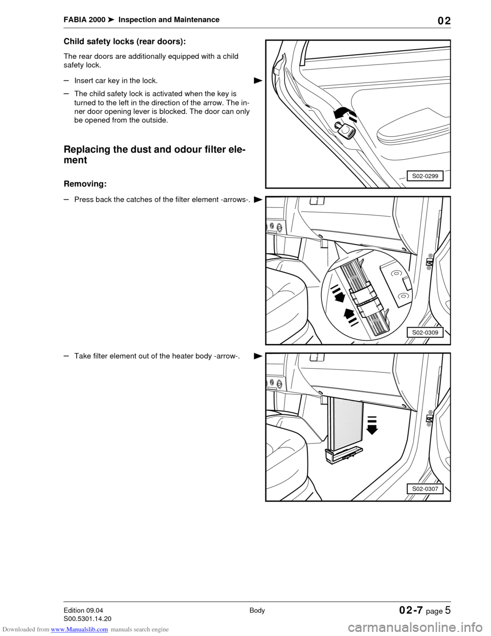
Child safety locks (rear doors):
The rear doors are additionally equipped with a child
safety lock.
–Insert car key in the lock.
–The child safety lock is activated when the key is
turned to the left in the direction of the arrow. The in-
ner door opening lever is blocked. The door can only
be opened from the outside.
Replacing the dust and odour filter ele-
ment
Removing:
–Press back the catches of the filter element -arrows-.
–Take filter element out of the heater body -arrow-.
S02-0299
S02-0309
S02-0307
Page 74 of 86

Downloaded from www.Manualslib.com manuals search engine FABIA 2000➤Inspection and Maintenance
BodyEdition 09.04
S00.5301.14.2002-7 page 6 02
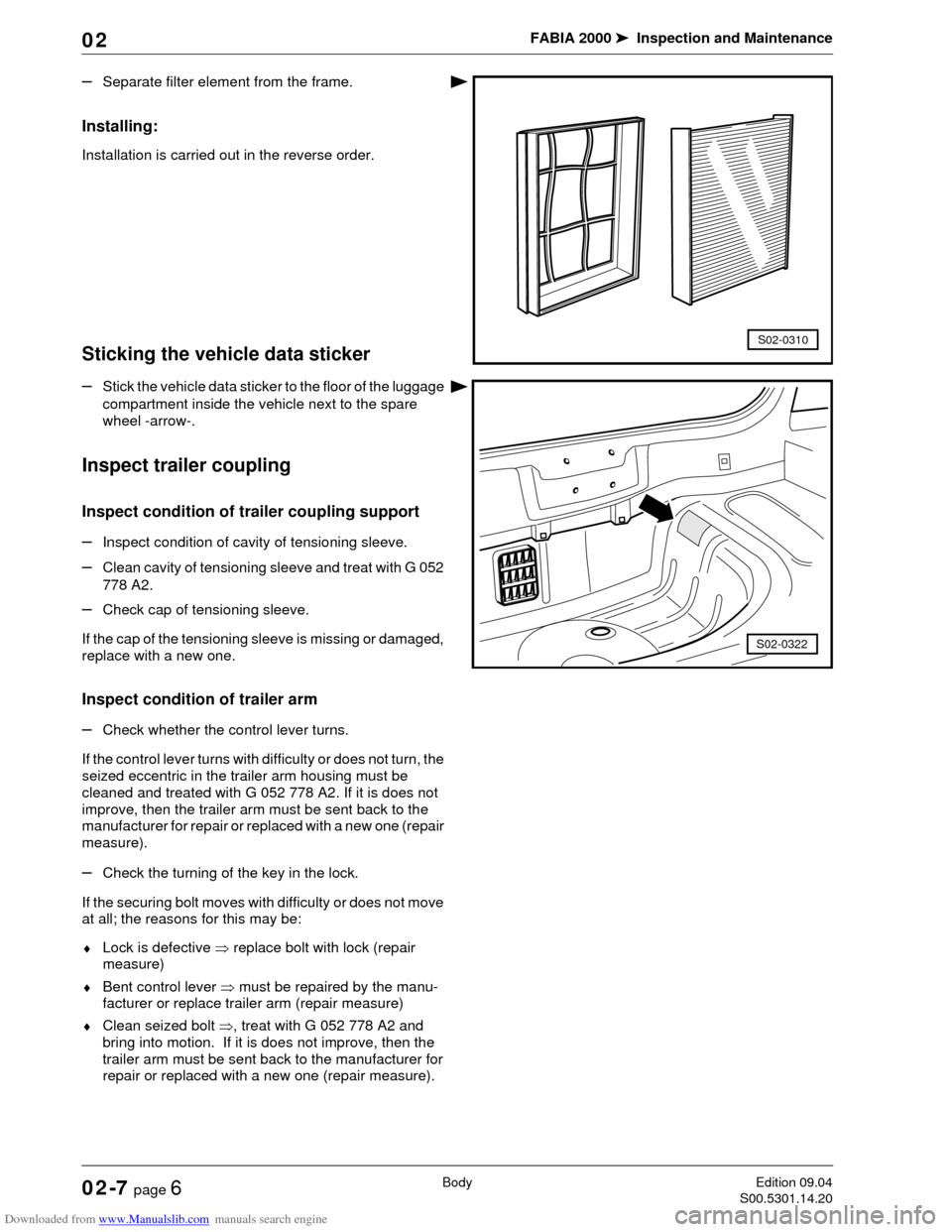
–Separate filter element from the frame.
Installing:
Installation is carried out in the reverse order.
Sticking the vehicle data sticker
–Stick the vehicle data sticker to the floor of the luggage
compartment inside the vehicle next to the spare
wheel -arrow-.
Inspect trailer coupling
Inspect condition of trailer coupling support
–Inspect condition of cavity of tensioning sleeve.
–Clean cavity of tensioning sleeve and treat with G 052
778 A2.
–Check cap of tensioning sleeve.
If the cap of the tensioning sleeve is missing or damaged,
replace with a new one.
Inspect condition of trailer arm
–Check whether the control lever turns.
If the control lever turns with difficulty or does not turn, the
seized eccentric in the trailer arm housing must be
cleaned and treated with G 052 778 A2. If it is does not
improve, then the trailer arm must be sent back to the
manufacturer for repair or replaced with a new one (repair
measure).
–Check the turning of the key in the lock.
If the securing bolt moves with difficulty or does not move
at all; the reasons for this may be:
♦Lock is defective ⇒ replace bolt with lock (repair
measure)
♦Bent control lever ⇒ must be repaired by the manu-
facturer or replace trailer arm (repair measure)
♦Clean seized bolt ⇒, treat with G 052 778 A2 and
bring into motion. If it is does not improve, then the
trailer arm must be sent back to the manufacturer for
repair or replaced with a new one (repair measure).
S02-0310
S02-0322
Page 75 of 86

Downloaded from www.Manualslib.com manuals search engine FABIA 2000➤Inspection and Maintenance
BodyEdition 09.04
S00.5301.14.2002-7 page 7 02
When applying G 052 778 A2 make sure that the product
does not penetrate into the gap between the lock bolt,
control lever, eccentric and trailer arm housing.
Trailer coupling: Check for proper operation
–Tighten trailer arm in the tensioning sleeve.
–Close lock and remove key.
–Check for correct closing by turning the control lever
downwards.
Note
WARNING!
If one of the measures cannot be carried out or if
the closed lever can be turned to an angle greater
than 5 , the trailer coupling is damaged and must
not be operated. The fault must be identified and
the damaged components must be replaced (repair
measure).