gearbox SKODA FABIA 2000 1.G / 6Y Owner's Manual
[x] Cancel search | Manufacturer: SKODA, Model Year: 2000, Model line: FABIA, Model: SKODA FABIA 2000 1.G / 6YPages: 86, PDF Size: 3.58 MB
Page 57 of 86
Downloaded from www.Manualslib.com manuals search engine FABIA 2000➤Inspection and Maintenance
Electrical SystemEdition 09.04
S00.5301.14.2002-6 page 3 02
holding the knob in the left or right position respective-
ly.
Connect vehicle system tester and inter-
rogate fault memory
The stored faults can be read out with vehicle system
tester -V.A.G 1552-, -V.A.G 1551-, or -V.A.S. 5051-.
♦The following description relates to vehicle system
tester -V.A.G 1552- using program card 6.0.
♦The use of vehicle diagnosis, measurement and infor-
mation system -V.A.S 5051- or fault read-out scan
tool -V.A.G 1551- with the program card version 9 is
similar. (A minor deviation on the display read-out is
possible).
Special tools, test and measuring equipment and
auxiliary items required
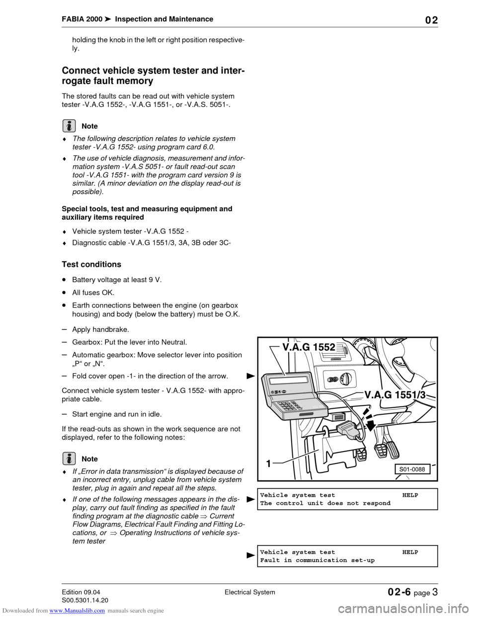
♦Vehicle system tester -V.A.G 1552 -
♦Diagnostic cable -V.A.G 1551/3, 3A, 3B oder 3C-
Test conditions
•Battery voltage at least 9 V.
•All fuses OK.
•Earth connections between the engine (on gearbox
housing) and body (below the battery) must be O.K.
–Apply handbrake.
–Gearbox: Put the lever into Neutral.
–Automatic gearbox: Move selector lever into position
„P“ or „N“.
–Fold cover open -1- in the direction of the arrow.
Connect vehicle system tester - V.A.G 1552- with appro-
priate cable.
–Start engine and run in idle.
If the read-outs as shown in the work sequence are not
displayed, refer to the following notes:
♦If „Error in data transmission“ is displayed because of
an incorrect entry, unplug cable from vehicle system
tester, plug in again and repeat all the steps.
♦If one of the following messages appears in the dis-
play, carry out fault finding as specified in the fault
finding program at the diagnostic cable ⇒Current
Flow Diagrams, Electrical Fault Finding and Fitting Lo-
cations, or ⇒Operating Instructions of vehicle sys-
tem tester
Note
1552V.A.
G
.H
E
LPQ O C9 8 76 5 43 2 1
Note
Vehicle system test HELP
The control unit does not respond
Vehicle system test HELP
Fault in communication set-up
Page 79 of 86

Downloaded from www.Manualslib.com manuals search engine FABIA 2000➤Inspection and Maintenance
Exhaust-emission AnalysisEdition 09.04
S00.5301.14.2002-8 page 3 02
Engine identification
charactersAZQAZE, AZF and
AMEAT Z A Q W
Model year MY03 ➤MY00 ➤ MY03 MY00 MY01 ➤ MY03
Oil temperature min. 80 °Cmin. 80 °C min. 80 °Cmin. 80 °C
Catalyst warming-up time2 min.
at 2500 rpm2 min.
at 2500 rpm2 min.
at 2500 rpm2 min.
at 2500 rpm
Idling speed
(rpm)650 ... 850 700 ... 900 700 ... 900 700 ... 900
CO content at idle speed
(measured after catalyst)0,0 ... 0,5% 0,0 ... 0,5% 0,0 ... 0,5% 0,0 ... 0,5%
Increased idling speed
(rpm)2400 - 2600 2400 - 2600 2400 - 2600 2400 - 2600
Lambda value
at 2850 - 2900 rpm0,97 ... 1,03 0,97 ... 1,03 0,97 ... 1,03 0,97 ... 1,03
CO content
at 2850 - 2900 rpmmax. 0.3% max. 0.3% max. 0.3% max. 0.3%
Speed for control loop
test (rpm)550 ... 950 600 ... 1000 600 ... 1000 600 ... 1000
Lambda probe version - - - -
Voltage jump (V) - - - -
DELTA-lambda 0,03 0,03 0,03 0,03
Test speed - - - -
Engine identification
charactersAUAAUA
with manual gear-
boxAUA
with automatic
gearboxBBY
with manual
gearbox
Model year MY00 and MY01 MY02 MY02 MY02 ➤
Oil temperature min. 80 °C min. 80 °C min. 80 °Cmin. 80 °C
Catalyst warming-up time2 min.
at 2500 rpm2 min.
at 2500 rpm2 min.
at 2500 rpm2 min.
at 2500 rpm
Idling speed
(rpm)650 ... 850 650 ... 850 580 ... 780 660 ... 860
CO content at idle speed
(measured after catalyst)0,0 ... 0,5% 0,0 ... 0,5% 0,0 ... 0,5% 0,0 ... 0,5%
Increased idling speed
(rpm)2400 - 2600 2400 - 2600 2400 - 2600 2400 - 2600
Lambda value
at 2850 - 2900 rpm0,97 ... 1,03 0,97 ... 1,03 0,97 ... 1,03 0,97 ... 1,03
CO content
at 2850 - 2900 rpmmax. 0.3% max. 0.3% max. 0.3% max. 0.3%
Speed for control loop
test (rpm)
550 ... 950 550 ... 950 480 ... 880 560 ... 960
Lambda probe versionWide band probe
(lambda)Wide band probe
(lambda)Wide band probe
(lambda)Wide band probe
(lambda)
Voltage jump (V) - - - -
DELTA-lambda 0,03 0,03 0,03 0,03
Test speed Idling speed Idling speed Idling speed Idling speed
Page 80 of 86

Downloaded from www.Manualslib.com manuals search engine FABIA 2000➤Inspection and Maintenance
Exhaust-emission AnalysisEdition 09.04
S00.5301.14.2002-8 page 4 02
Engine identification
charactersBBY
with automatic
gearboxAUB BBZ AZL
Model year MY02 ➤MY00 ➤ MY02 MY02 ➤MY01 ➤
Oil temperature min. 80 °C min. 80 °C min. 80 °Cmin. 80 °C
Catalyst warming-up time2 min.
at 2500 rpm2 min.
at 2500 rpm2 min.
at 2500 rpm2 min.
at 2500 rpm
Idling speed
(rpm)580 ... 780 740 ... 940 580 ... 780 680 ... 880
CO content at idle speed
(measured after catalyst)0,0 ... 0,5% 0,0 ... 0,5% 0,0 ... 0,5% 0,0 ... 0,5%
Increased idling speed
(rpm)2400 - 2600 2400 - 2600 2400 - 2600 2400 - 2600
Lambda value
at 2850 - 2900 rpm0,97 ... 1,03 0,97 ... 1,03 0,97 ... 1,03 0,97 ... 1,03
CO content
at 2850 - 2900 rpmmax. 0.3% max. 0.3% max. 0.3% max. 0.3%
Speed for control loop
test (rpm)480 ... 880 640 ... 1040 480 ... 880 580 ... 980
Lambda probe versionWide band probe
(lambda)Wide band probe
(lambda)Wide band probe
(lambda)-
Voltage jump (V) - - - -
DELTA-lambda 0,03 0,03 0,03 0,03
Test speed Idling speed Idling speed Idling speed -
Engine identification
charactersBMD BKY
Model year MY04 ➤MY04 ➤
Oil temperature min. 80 °C min. 80 °C
Catalyst warming-up time2 min.
at 2500 rpm2 min.
at 2500 rpm
Idling speed
(rpm)620 ... 820 660 ... 860
CO content at idle speed
(measured after catalyst)0,0 ... 0,5% 0,0 ... 0,5%
Increased idling speed
(rpm)2400 - 2600 2400 - 2600
Lambda value
at 2850 - 2900 rpm0,97 ... 1,03 0,97 ... 1,03
CO content
at 2850 - 2900 rpmmax. 0.3% max. 0.3%
Speed for control loop
test (rpm)520 ... 920 560 ... 960
Lambda probe version Jump probeWide band probe
(lambda)
Voltage jump (V) - -
DELTA-lambda 0,03 0,03
Test speed - -
Page 81 of 86
Downloaded from www.Manualslib.com manuals search engine FABIA 2000➤Inspection and Maintenance
Exhaust-emission AnalysisEdition 09.04
S00.5301.14.2002-8 page 5 02
All tubes and plug connections, which had been removed
or disconnected for the test and adjustment, must be re-
inserted or connected.
Technical data of the spark plugs Chapter 02-3.
Exhaust-Emission Analysis on Models
with Diesel Engines
♦When possible the test should be carried out immedi-
ately after the road test and also outdoors. If specific
reasons prevent this (weather conditions, excessive
noise in residential areas) the test may also be per-
formed in the workshop.
♦Secure the engine bonnet in the first stop while meas-
uring to reduce the noise.
Visual inspection
♦Hose for crankcase ventilation is connected
♦Fuel system and injection pump must be tight
♦The exhaust system must be undamaged and tight
♦All vacuum hoses are connected
Test and setting conditions
•Engine oil temperature at least 80 °C
•All electrical components disconnected
•No fault stored in the fault memory ⇒Chapter 02-6,
connect vehicle system tester and interrogate fault
memory
Correct detected faults before measuring (repair meas-
ure).
Connect the test equipment
–Connect the tester in compliance with the operating
instructions.
–Start engine, warm up to normal temperature and run
in idle.
–Perform the exhaust-emission analysis.
♦Activate and inspect auxiliary equipment such as e.g.
power steering, automatic gearbox or air conditioning
system. Check whether the engine continues to run
perfectly under this load.
♦All tubes and plug connections, which had been re-
moved or disconnected for the test and adjustment,
must be re-inserted or connected.
Note
Note
Note
Note
Page 83 of 86
Downloaded from www.Manualslib.com manuals search engine FABIA 2000➤Inspection and Maintenance
MiscellaneousEdition 06.01
S00.5301.06.2002-9 page 1 02
02-9 Miscellaneous
Tow starting/Towing
♦A towing rope or towing bar must only be fitted to the
above towing lugs.
♦The towing rope must be elastic to protect the vehicle.
Therefore only use synthetic ropes or ropes manufac-
tured in an equally elastic material. However, it is saf-
er to use a towing bar!
♦Make sure no unauthorised traction forces and no jolt-
ing loads are exerted. During towing manoeuvres
away from hardened road surfaces there is a risk of
overloading and damaging the fixation parts.
♦Before starting the engine by towing, first use the bat-
tery of another vehicle as a start aid.
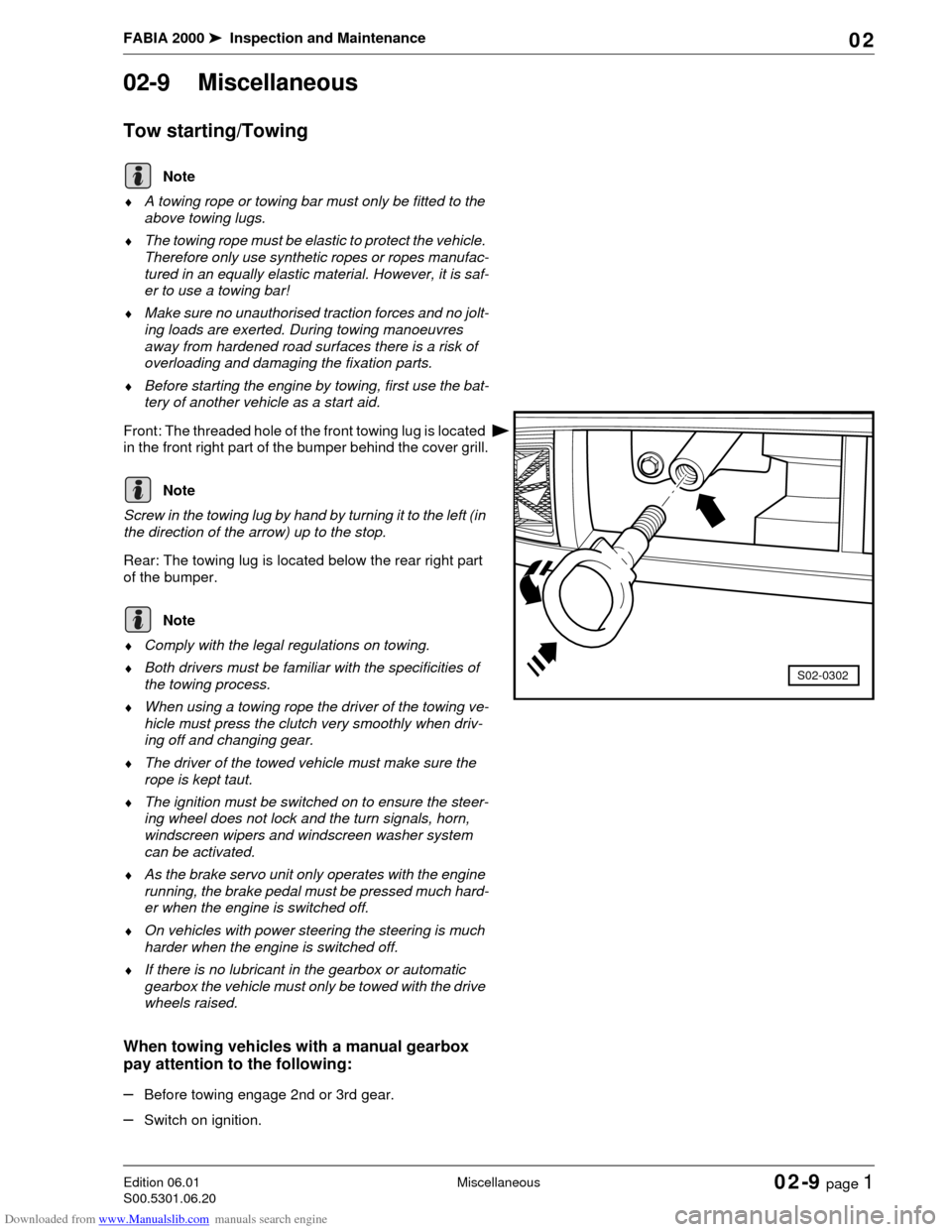
Front: The threaded hole of the front towing lug is located
in the front right part of the bumper behind the cover grill.
Screw in the towing lug by hand by turning it to the left (in
the direction of the arrow) up to the stop.
Rear: The towing lug is located below the rear right part
of the bumper.
♦Comply with the legal regulations on towing.
♦Both drivers must be familiar with the specificities of
the towing process.
♦When using a towing rope the driver of the towing ve-
hicle must press the clutch very smoothly when driv-
ing off and changing gear.
♦The driver of the towed vehicle must make sure the
rope is kept taut.
♦The ignition must be switched on to ensure the steer-
ing wheel does not lock and the turn signals, horn,
windscreen wipers and windscreen washer system
can be activated.
♦As the brake servo unit only operates with the engine
running, the brake pedal must be pressed much hard-
er when the engine is switched off.
♦On vehicles with power steering the steering is much
harder when the engine is switched off.
♦If there is no lubricant in the gearbox or automatic
gearbox the vehicle must only be towed with the drive
wheels raised.
When towing vehicles with a manual gearbox
pay attention to the following:
–Before towing engage 2nd or 3rd gear.
–Switch on ignition.
Note
S02-0302
Note
Note
Page 84 of 86
Downloaded from www.Manualslib.com manuals search engine FABIA 2000➤Inspection and Maintenance
MiscellaneousEdition 06.01
S00.5301.06.2002-9 page 2 02
–As soon as the engine starts, press clutch and remove
gear to avoid driving into the towing vehicle.
Do not start the engine of vehicles fitted with an exhaust
catalyst by towing over a long distance as unburnt fuel
may get into the catalyst and burn there. This may result
in overheating and hence in the destruction of the cata-
lyst.
Perform a test drive
The following must be assessed within the scope of a test
drive according to the vehicle equipment and the availa-
ble possibilities (city/country, weather)
–Inspect engine for performance, misfiring, idling be-
haviour and acceleration.
–Foot and handbrake: Functional test (jerking, squeak-
ing, pulling to one side) ABS operation. Brake pedal-
idle travel: max.
1/3 of the idle travel.
–Inspect the lever position and smooth operation of the
gearshifts.
–Inspect the driving behaviour of the clutch as well as
the pedal force and smell.
–Inspect automatic gearbox: Selector lever position,
selector lever lock, shifting behaviour, display indica-
tion in dash panel insert.
–Inspect steering clearance of the vehicle standing on
its wheels, with engine running by turning the steering
wheel one way and then the other (wheels straight
ahead). There must be no play on the steering.
–Inspecting the sun roof operation.
–Pay attention to pulling and to the straigt ahead posi-
tion of the steering wheel during driving.
–Inspect the imbalance of the wheels, drive shafts and
propshafts.
–Inspecting functions: Heating, air conditioning, venti-
lation, instruments and warning lights, mirror adjust-
ment.
–Inspect engine, gearbox, axles, steering, brakes,
clutch, bodywork for abnormal noises
Raising the vehicle
Using a lift platform and a workshop jack
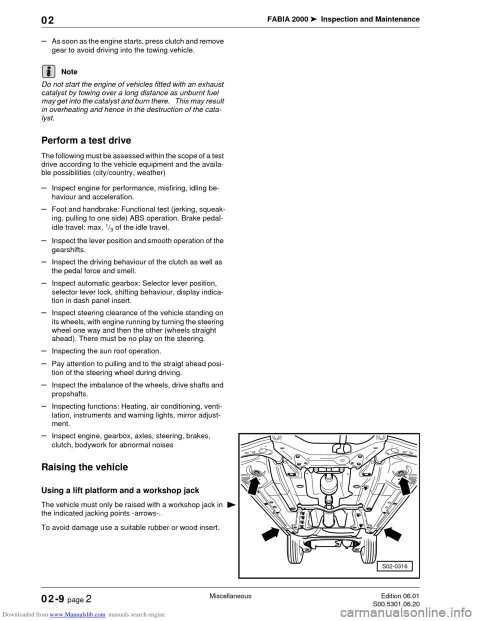
The vehicle must only be raised with a workshop jack in
the indicated jacking points -arrows-.
To avoid damage use a suitable rubber or wood insert.
Note
S02-0316
Page 85 of 86
Downloaded from www.Manualslib.com manuals search engine FABIA 2000➤Inspection and Maintenance
MiscellaneousEdition 06.01
S00.5301.06.2002-9 page 3 02
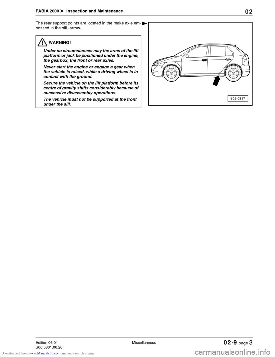
The rear support points are located in the make axle em-
bossed in the sill -arrow-.
S02-0317
WARNING!
Under no circumstances may the arms of the lift
platform or jack be positioned under the engine,
the gearbox, the front or rear axles.
Never start the engine or engage a gear when
the vehicle is raised, while a driving wheel is in
contact with the ground.
Secure the vehicle on the lift platform before its
centre of gravity shifts considerably because of
successive disassembly operations.
The vehicle must not be supported at the front
under the sill.