wheel SKODA FABIA 2004 1.G / 6Y User Guide
[x] Cancel search | Manufacturer: SKODA, Model Year: 2004, Model line: FABIA, Model: SKODA FABIA 2004 1.G / 6YPages: 247
Page 76 of 247
Seats and Stowage75
Using the systemSafetyDriving TipsGeneral MaintenanceBreakdown assistanceTechnical Data
Fixing of the floor covering of the luggage
compartment
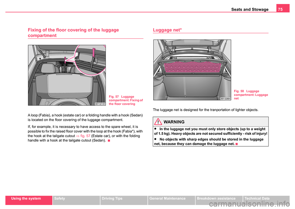
A loop (Fabia), a hook (estate car) or a folding handle with a hook (Sedan)
is located on the floor covering of the luggage compartment.
If, for example, it is necessary to have access to the spare wheel, it is
possible to fix the raised floor cover with the loop at the hook (Fabia*), with
the hook at the tailgate cutout ⇒fig. 57 (Estate car), or with the folding
handle with a hook at the tailgate cutout (Sedan).
Luggage net*
The luggage net is designed for the tranportation of lighter objects.
WARNING
•In the luggage net you must only store objects (up to a weight
of 1.5 kg). Heavy objects are not secured sufficiently - risk of injury!
•No objects with sharp edges should be stored in the luggage
net, because they can damage the luggage net.
Fig. 57 Luggage
compartment: Fixing of
the floor covering
Fig. 58 Luggage
compartment: Luggage
net
Page 88 of 247
Seats and Stowage87
Using the systemSafetyDriving TipsGeneral MaintenanceBreakdown assistanceTechnical Data
Cooling of storage compar tment on front passenger
side*
The storage compartment is for vehicles fitted with an air-
conditioning system with a closable inlet for cooled air.
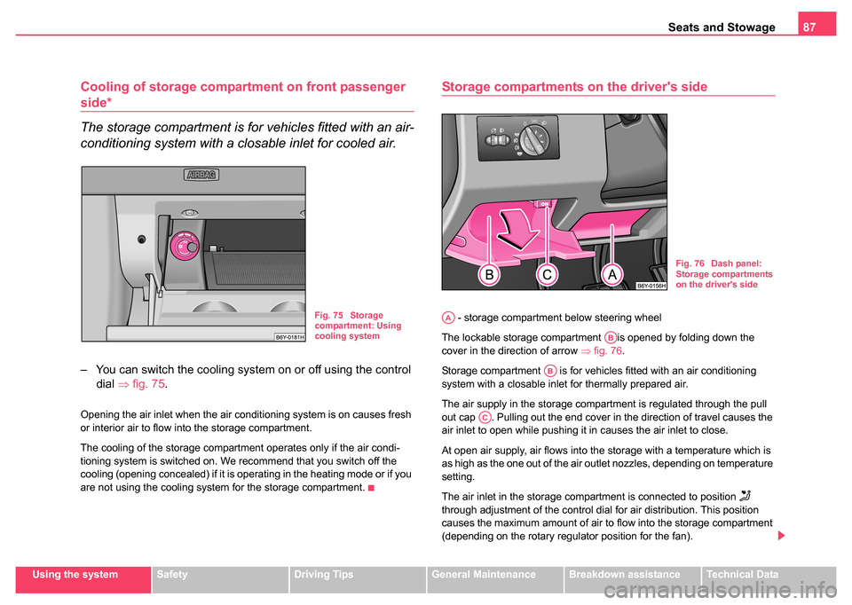
– You can switch the cooling system on or off using the control
dial ⇒fig. 75.
Opening the air inlet when the air conditioning system is on causes fresh
or interior air to flow into the storage compartment.
The cooling of the storage compartment operates only if the air condi-
tioning system is switched on. We recommend that you switch off the
cooling (opening concealed) if it is operating in the heating mode or if you
are not using the cooling system for the storage compartment.
Storage compartments on the driver's side
- storage compartment below steering wheel
The lockable storage compartment is opened by folding down the
cover in the direction of arrow ⇒fig. 76.
Storage compartment is for vehicles fitted with an air conditioning
system with a closable inlet for thermally prepared air.
The air supply in the storage compartment is regulated through the pull
out cap . Pulling out the end cover in the direction of travel causes the
air inlet to open while pushing it in causes the air inlet to close.
At open air supply, air flows into the storage with a temperature which is
as high as the one out of the air outlet nozzles, depending on temperature
setting.
The air inlet in the storage compartment is connected to position
through adjustment of the control dial for air distribution. This position
causes the maximum amount of air to flow into the storage compartment
(depending on the rotary regulator position for the fan).
Fig. 75 Storage
compartment: Using
cooling system
Fig. 76 Dash panel:
Storage compartments
on the driver's side
AA
AB
AB
AC
Page 94 of 247
Heating and air conditioning system 93
Using the systemSafetyDriving TipsGeneral MaintenanceBreakdown assistanceTechnical Data
•Open air outlet vents 3 and 4 ⇒ page 93, fig. 85
The control dial can be set to other positions as required.
Recirculated air mode
In recirculated air mode air is sucked out of the interior of
the vehicle and then fed back into the interior.
Recirculated air mode prevents polluted air outside the vehicle
from getting into the vehicle, for example when driving through a
tunnel or when standing in a traffic jam.
Switching recirculated air mode on
– Press button , the button symbol
lights up ⇒page 91,
fig. 84.
Switching recirculated air mode off
– Press button again, the button symbol
goes out.
The recirculated air mode is switched off automatically if the air distribu-
tion control is in position ⇒ page 91, fig. 84 .
WARNING
You should not leave recirculated air mode on over a longer period
of time. “Stale air” may result in fatigue in the driver and passen-
gers, reduce attention levels and also cause the windows to mist
up. The risk of having an accident increases. Switch recirculated
air mode off as soon as the windows begin misting up.
Air outlet vents
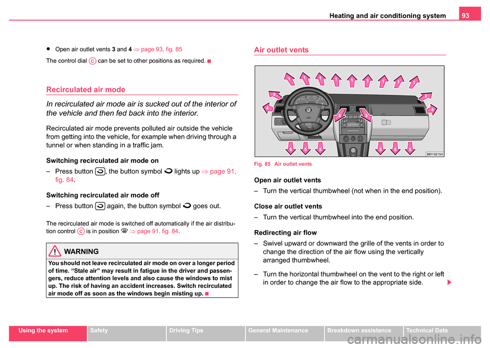
Fig. 85 Air outlet vents
Open air outlet vents
– Turn the vertical thumbwheel (not when in the end position).
Close air outlet vents
– Turn the vertical thumbwheel into the end position.
Redirecting air flow
– Swivel upward or downward the gr ille of the vents in order to
change the direction of the air flow using the vertically
arranged thumbwheel.
– Turn the horizontal thumbwheel on the vent to the right or left in order to change the air flow to the appropriate side.
AC
AC
Page 99 of 247
Heating and air conditioning system
98
Air outlet vents
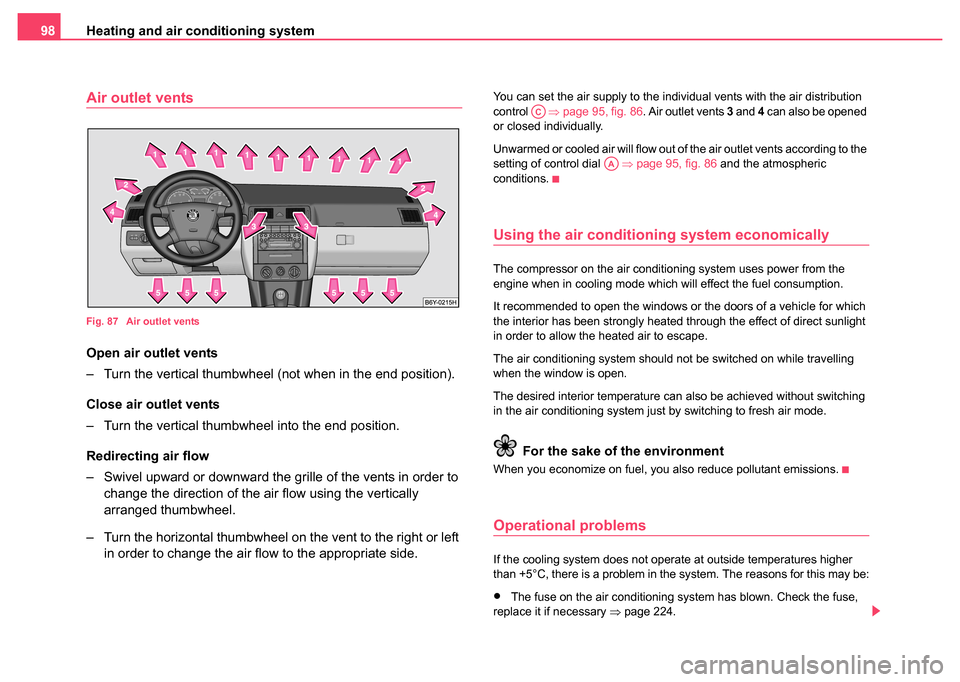
Fig. 87 Air outlet vents
Open air outlet vents
– Turn the vertical thumbwheel (not when in the end position).
Close air outlet vents
– Turn the vertical thumbwheel into the end position.
Redirecting air flow
– Swivel upward or downward the gril le of the vents in order to
change the direction of the air flow using the vertically
arranged thumbwheel.
– Turn the horizontal thumbwheel on the vent to the right or left in order to change the air flow to the appropriate side.
You can set the air supply to the individual vents with the air distribution
control ⇒page 95, fig. 86 . Air outlet vents 3 and 4 can also be opened
or closed individually.
Unwarmed or cooled air will flow out of the air outlet vents according to the
setting of control dial ⇒page 95, fig. 86 and the atmospheric
conditions.
Using the air conditioning system economically
The compressor on the air conditioning system uses power from the
engine when in cooling mode which will effect the fuel consumption.
It recommended to open the windows or the doors of a vehicle for which
the interior has been strongly heated through the effect of direct sunlight
in order to allow the heated air to escape.
The air conditioning system should not be switched on while travelling
when the window is open.
The desired interior temperature can also be achieved without switching
in the air conditioning system just by switching to fresh air mode.
For the sake of the environment
When you economize on fuel, you also reduce pollutant emissions.
Operational problems
If the cooling system does not operate at outside temperatures higher
than +5°C, there is a problem in the system. The reasons for this may be:
•The fuse on the air conditioning system has blown. Check the fuse,
replace it if necessary ⇒page 224.
AC
AA
Page 101 of 247
Starting-off and Driving
100
Starting-off and Driving
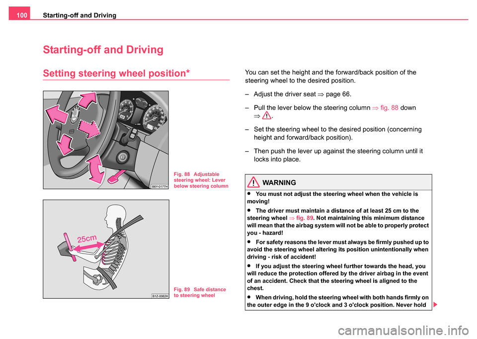
Setting steering wheel position*You can set the height and the forward/back position of the
steering wheel to the desired position.
– Adjust the driver seat ⇒page 66.
– Pull the lever below the steering column ⇒fig. 88 down
⇒ .
– Set the steering wheel to the desired position (concerning height and forward/back position).
– Then push the lever up against the steering column until it locks into place.
WARNING
•You must not adjust the steering wheel when the vehicle is
moving!
•The driver must maintain a distance of at least 25 cm to the
steering wheel ⇒fig. 89 . Not maintaining this minimum distance
will mean that the airbag system will not be able to properly protect
you - hazard!
•For safety reasons the lever must always be firmly pushed up to
avoid the steering wheel altering its position unintentionally when
driving - risk of accident!
•If you adjust the steering wheel further towards the head, you
will reduce the protection offered by the driver airbag in the event
of an accident. Check that the steering wheel is aligned to the
chest.
•When driving, hold the steering wheel with both hands firmly on
the outer edge in the 9 o'clock and 3 o'clock position. Never hold
Fig. 88 Adjustable
steering wheel: Lever
below steering column
Fig. 89 Safe distance
to steering wheel
Page 102 of 247
Starting-off and Driving101
Using the systemSafetyDriving TipsGeneral MaintenanceBreakdown assistanceTechnical Data
the steering wheel firmly in the 12 o'clock position or in another
way (e.g. in the middle of the steering wheel or at the inner steering
wheel edge). In such cases, injuries to the arms, the hands and the
head can occur when the driver airbag is deployed.
Ignition lock
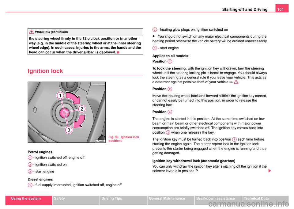
Petrol engines
- ignition switched off, engine off
- ignition switched on
- start engine
Diesel engines - fuel supply interrupted, ignition switched off, engine off - heating glow plugs on, ignition switched on
•You should not switch on any major electrical components during the
heating period otherwise the vehicle battery will be drained unnecessarily.
- start engine
Applies to all models:
Position
To lock the steering , with the ignition key withdrawn, turn the steering
wheel until the steering locking pin is heard to engage. You should always
lock the steering as a general rule if you leave your vehicle. This acts as
a deterrent against possible theft of your vehicle ⇒.
Position
Move the steering wheel back and forward a little if the ignition key cannot,
or cannot easily be turned into this position, in order to release the
steering lock.
Position
The engine is started in this position. At the same time switched on low
beam or main beam or other electrical components with major power
consumption are briefly switched off. The ignition key moves back into
position when one releases the key.
The ignition key must be turned back into position each time before
starting the engine again. The starter repeat lock in the ignition lock
prevents the starter being engaged when the engine is running and thus
getting damaged.
Ignition key withdrawal lock (automatic gearbox)
You can only withdraw the ignition key after switching off the ignition if the
selector lever is in position P.WARNING (continued)
Fig. 90 Ignition lock
positions
A1
A2
A3
A1
A2
A3
A1
A2
A3
A2
A1
Page 103 of 247
Starting-off and Driving
102
WARNING
•When driving, the ignition key must always be in the position
(ignition switched on) without the engine running. This position is
indicated by the warning lights coming on. If this is not the case, it
could result in unexpected locking of the steering wheel - risk of
accident!
•Only remove the ignition key fr om the ignition lock when the
vehicle has come to a standstill (put on the handbrake or select the
selector lever position P). The steering lock might otherwise
engage unintentionally - risk of accident!
•Always withdraw the ignition key if you are going to leave the
vehicle, even for a short time. This is particularly important if chil-
dren are left in the vehicle. The children might otherwise start the
engine or operate electrical equi pment (e.g. power windows) - risk
of injury!
Starting engine
General
You can only start the engine only using an original ignition
key.
•Place the gearshift lever into neutral (or place the selector lever to the
position P or N in the case of an automatic gearbox) and put on the hand-
brake firmly before starting the engine.
•The clutch pedal should be fully depressed when starting the engine
which means that the starter only has to crank the engine.
•Let go of the key as soon as the engine starts otherwise there may be
damage to the starter. The engine running noises may louder at first be louder for a short time
after starting the cold engine until oil pressure can be built up in the
hydraulic valve clearance compensation. This is quite normal and is not
an operating problem.
If the engine does not start ...
You can use the battery of another vehicle as a jump-start aid
⇒
page 218.
It is only possible to tow-start vehicles fitted with a manual gearbox. The
tow-starting distance must not be more than 50 metres ⇒page 222.
WARNING
•Never run the engine in non ventilated or enclosed areas. The
exhaust gases of the engine contain besides the odorless and
colourless carbon monoxide a poisonous gas - hazard! Carbon
monoxide can cause unconsciousness and death.
•Never leave your vehicle unattended with the engine running.
Caution
•The starter may only be operated (ignition key position ), if the
engine is not running. If the starter is immediately operated after switching
off the engine, the starter or the engine can be damaged.
•Avoid high engine revolutions, full throttle and high engine loads as
long as the engine has not yet reached its normal operating temperature
- risk of damaging the engine!
•Vehicles which are fitted with an exhaust gas catalytic converter
should not be tow-started over a distance of more than 50 metres.
A2
A3
Page 112 of 247
Automatic gearbox*111
Using the systemSafetyDriving TipsGeneral MaintenanceBreakdown assistanceTechnical Data
Selector lever positions
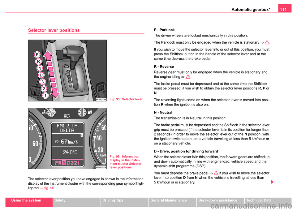
The selector lever position you have engaged is shown in the information
display of the instrument cluster with the corresponding gear symbol high-
lighted ⇒fig. 96. P - Parklock
The driven wheels are locked mechanically in this position.
The Parklock must only be engaged when the vehicle is stationary
⇒.
If you wish to move the selector lever into or out of this position, you must
press the Shiftlock button in the handle of the selector lever and at the
same time depress the brake pedal.
R - Reverse
Reverse gear must only be engaged when the vehicle is stationary and
the engine idling ⇒.
The brake pedal must be depressed and at the same time the Shiftlock
must be pressed, if you wish to obtain the selector lever positions R, P or
N .
The reversing lights come on when the selector lever is moved into posi-
tion R when the ignition is also on.
N - Neutral
The transmission is in Neutral in this position.
The brake pedal must be depressed and the Shiftlock in the selector lever
grip must be pressed (if the selector lever is in its position for longer than
2 seconds) in order to move the selector lever out of the N position, with
the ignition switched on, on a vehicle travelling at less than 5 km/hour or
on a stationary vehicle.
D - Drive, position for driving forward
When the selector lever is in this position, the forward gears are shifted up
and down automatically in line with engine load, vehicle speed and the
dynamic shift programme (DSP).
You must depress the brake pedal ⇒ if you wish to move the selector
lever into position D from N when the vehicle is travelling at less than
5 km/hour or is stationary.
Fig. 95 Selector lever
Fig. 96 Information
display in the instru-
ment cluster Selector
lever positions
Page 114 of 247
Automatic gearbox*113
Using the systemSafetyDriving TipsGeneral MaintenanceBreakdown assistanceTechnical Data
Selector lever lock
Automatic selector lever lock
With the ignition on, the selector lever is locked when it is in the positions
P and N. You must depress the brake pedal first and press the Shiftlock
button at the same time in order to move the selector lever out of these
positions. The following will be displayed in the information display*:
P LOCKED
or
N LOCKED
Symbol
also lights up in the selector lever cover until the brake pedal
is actuated.
A time delay element ensures that the selector lever is not blocked when
rapidly switching over the position N (e.g. from R to D). This does, for
example, allow one to seesaw out a stuck vehicle. The selector lever lock
will click into place if the lever is in the N position for more than 2 seconds
without the brake pedal being pressed.
The selector lever lock is only active if the vehicle is stationary or moving
at speed of less than 5 km/hour. The lock is switched off automatically into
position N when the car is travelling at a higher speed.
Shiftlock button
The Shiftlock button in the handle of selector lever prevents certain
selector lever positions being engaged inadvertently. The selector lever
lock is cancelled when you press the Shiftlock button.
Kickdown function
The kickdown function provides you with maximum accel-
eration power.
Depressing the accelerator pedal beyond the pressure point casues the
automatic gearbox to shift down into a lower gear (in line with vehicle
speed and engine speed). The gearbox shifts up into the next higher gear
when the engine has reached its maximum revolations.
WARNING
Please note that using the kickdown function can result in the
driven wheels spinning on a smooth or slippery road surface - risk
of skidding!
Dynamic shift programme
The automatic gearbox of your vehicle is controlled electronically. Shifting
up and down through the gears is performed automatically on the basis of
pre-defined driving programmes.
Adopting a moderate style of driving will cause the gearbox to select the
most economical driving programme. Shifting up into a higher gear as
soon as possible and shifting down as late as possible will have a favour-
able effect on your fuel consumption.
Adopting a faster style of driving with rapid movements of the acceler-
ator pedal combined with sharp acceleration and frequent changes in
speed, exploiting the top speed of the car or operating the kickdown func-
tion, will cause the gearbox to switch over to the sporty driving
programme. Shifting up later into a higher gear makes it possible to fully
exploit the power reserves of the engine. The gearbox also then shifts
Page 120 of 247
Passive Safety119
Using the systemSafetyDriving TipsGeneral MaintenanceBreakdown assistanceTechnical Data
Correct seated position
Correct seated position for the driver
Correct seated position for the driver is important for safe
and relaxed driving.
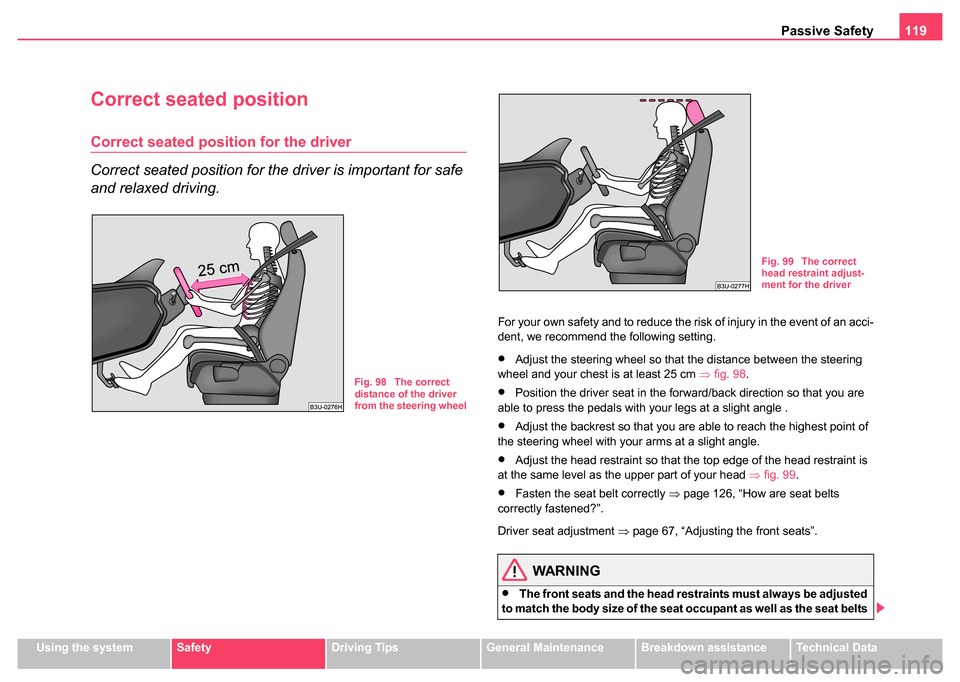
For your own safety and to reduce the risk of injury in the event of an acci-
dent, we recommend the following setting.
•Adjust the steering wheel so that the distance between the steering
wheel and your chest is at least 25 cm ⇒fig. 98 .
•Position the driver seat in the forward/back direction so that you are
able to press the pedals with your legs at a slight angle .
•Adjust the backrest so that you are able to reach the highest point of
the steering wheel with your arms at a slight angle.
•Adjust the head restraint so that the top edge of the head restraint is
at the same level as the upper part of your head ⇒fig. 99 .
•Fasten the seat belt correctly ⇒page 126, “How are seat belts
correctly fastened?”.
Driver seat adjustment ⇒page 67, “Adjusting the front seats”.
WARNING
•The front seats and the head restraints must always be adjusted
to match the body size of the seat occupant as well as the seat belts
Fig. 98 The correct
distance of the driver
from the steering wheel
Fig. 99 The correct
head restraint adjust-
ment for the driver