technical data SKODA FABIA 2004 1.G / 6Y Owner's Manual
[x] Cancel search | Manufacturer: SKODA, Model Year: 2004, Model line: FABIA, Model: SKODA FABIA 2004 1.G / 6YPages: 247
Page 4 of 247
Introduction3
Technical Data
includes the most important identification data of your vehicle.
Page 7 of 247
Contents
6
Driving Tips . . . . . . . . . . . . . . . . . . . . . .
Intelligent Technology . . . . . . . . . . . . . . . . . .
Electronic stability programme (ESP)* . . . . . .
Brakes . . . . . . . . . . . . . . . . . . . . . . . . . . . . . .
Brake booster . . . . . . . . . . . . . . . . . . . . . . . .
Antilock brake system (ABS)* . . . . . . . . . . . .
Power steering* . . . . . . . . . . . . . . . . . . . . . . .
Driving and the Environment. . . . . . . . . . . .
The first 1 500 kilometres and then afterwards
Catalytic converter . . . . . . . . . . . . . . . . . . . . .
Driving in an economical and environmentally
conscious manner . . . . . . . . . . . . . . . . . . . . .
Environmental compatibility . . . . . . . . . . . . . .
Motoring abroad . . . . . . . . . . . . . . . . . . . . . . .
Avoiding damage to your vehicle . . . . . . . . . .
Towing a trailer . . . . . . . . . . . . . . . . . . . . . . . .
Towing a trailer . . . . . . . . . . . . . . . . . . . . . . . .
Detachable towing device* . . . . . . . . . . . . . .
General Maintenance . . . . . . . . . .
Care and cleaning . . . . . . . . . . . . . . . . . . . . .
General . . . . . . . . . . . . . . . . . . . . . . . . . . . . .
Care of the exterior of vehicle . . . . . . . . . . . .
Care of the interior of vehicle . . . . . . . . . . . . .
Fuel. . . . . . . . . . . . . . . . . . . . . . . . . . . . . . . . . .
Petrol . . . . . . . . . . . . . . . . . . . . . . . . . . . . . . .
Diesel . . . . . . . . . . . . . . . . . . . . . . . . . . . . . . .
Refuelling . . . . . . . . . . . . . . . . . . . . . . . . . . . .
Inspecting and Replenishing. . . . . . . . . . . .
Engine compartment . . . . . . . . . . . . . . . . . . .
Engine oil . . . . . . . . . . . . . . . . . . . . . . . . . . . .
Cooling system . . . . . . . . . . . . . . . . . . . . . . .
Brake fluid . . . . . . . . . . . . . . . . . . . . . . . . . . . The battery . . . . . . . . . . . . . . . . . . . . . . . . . .
Windscreen Wiper and Washer System . . . .
Wheels and Tyres . . . . . . . . . . . . . . . . . . . . .
Wheels . . . . . . . . . . . . . . . . . . . . . . . . . . . . .
Accessories, changes and replacement of
parts . . . . . . . . . . . . . . . . . . . . . . . . . . . . . . . . .
Accessories and replacement parts . . . . . . .
Technical changes . . . . . . . . . . . . . . . . . . . . .
Breakdown assistance . . . . . . . .
Breakdown assistance . . . . . . . . . . . . . . . . .
First-aid box* and warning triangle* . . . . . . . .
Fire extinguisher* . . . . . . . . . . . . . . . . . . . . . .
Vehicle tool kit . . . . . . . . . . . . . . . . . . . . . . . .
Spray for repairing a tyre* . . . . . . . . . . . . . . .
Tyre repair kit* . . . . . . . . . . . . . . . . . . . . . . . .
Spare wheel* . . . . . . . . . . . . . . . . . . . . . . . . .
Changing a wheel . . . . . . . . . . . . . . . . . . . . .
Jump-starting . . . . . . . . . . . . . . . . . . . . . . . . .
Tow-starting and towing vehicle . . . . . . . . . . .
Fuses and light bulbs . . . . . . . . . . . . . . . . . .
Electric fuses . . . . . . . . . . . . . . . . . . . . . . . . .
Bulbs . . . . . . . . . . . . . . . . . . . . . . . . . . . . . . .
Technical Data. . . . . . . . . . . . . . . . . . .
General . . . . . . . . . . . . . . . . . . . . . . . . . . . . . .
Identification data . . . . . . . . . . . . . . . . . . . . .
Index. . . . . . . . . . . . . . . . . . . . . . . . . . . . . . .
151
151
151
154
155
155
156
157
157
158
159
163
164
164
165
165
167
169
169
169
169
175
178
178
178
180
182
182
185
189
191 193
197
199
199
206
206
206
209
209
209
209
210
211
211
212
212
218
220
224
224
227
237
237
237
239
Page 10 of 247
9
Using the systemSafetyDriving TipsGeneral MaintenanceBreakdown assistanceTechnical Data
Using the system
Page 12 of 247
Cockpit11
Using the systemSafetyDriving TipsGeneral MaintenanceBreakdown assistanceTechnical Data
Cockpit
An overview
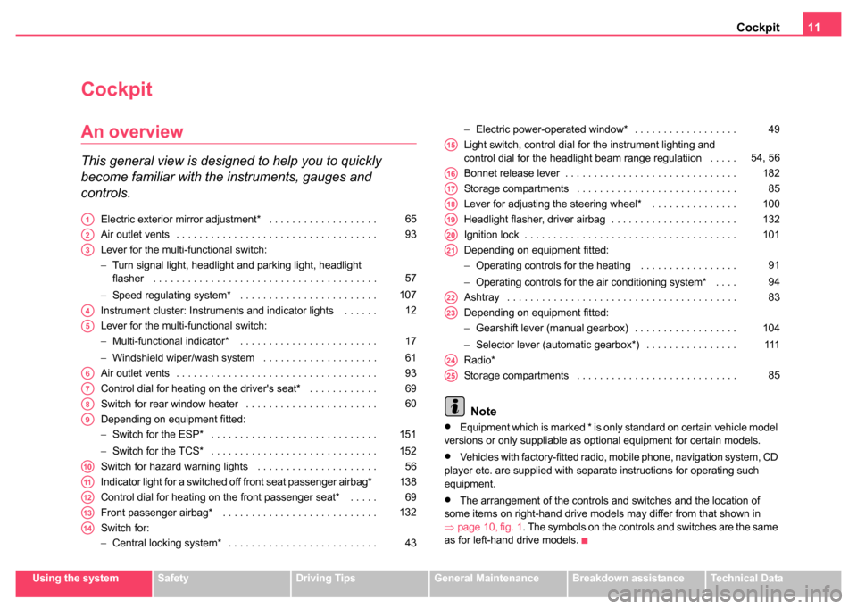
This general view is designed to help you to quickly
become familiar with the instruments, gauges and
controls.
Electric exterior mirror adjustment* . . . . . . . . . . . . . . . . . . .
Air outlet vents . . . . . . . . . . . . . . . . . . . . . . . . . . . . . . . . . . .
Lever for the multi-functional switch:
−Turn signal light, headlight and parking light, headlight
flasher . . . . . . . . . . . . . . . . . . . . . . . . . . . . . . . . . . . . . . .
− Speed regulating system* . . . . . . . . . . . . . . . . . . . . . . . .
Instrument cluster: Instruments and indicator lights . . . . . .
Lever for the multi-functional switch:
− Multi-functional indicator* . . . . . . . . . . . . . . . . . . . . . . . .
− Windshield wiper/wash system . . . . . . . . . . . . . . . . . . . .
Air outlet vents . . . . . . . . . . . . . . . . . . . . . . . . . . . . . . . . . . .
Control dial for heating on the driver's seat* . . . . . . . . . . . .
Switch for rear window heater . . . . . . . . . . . . . . . . . . . . . . .
Depending on equipment fitted:
− Switch for the ESP* . . . . . . . . . . . . . . . . . . . . . . . . . . . . .
− Switch for the TCS* . . . . . . . . . . . . . . . . . . . . . . . . . . . . .
Switch for hazard warning lights . . . . . . . . . . . . . . . . . . . . .
Indicator light for a switched off front seat passenger airbag*
Control dial for heating on the front passenger seat* . . . . .
Front passenger airbag* . . . . . . . . . . . . . . . . . . . . . . . . . . .
Switch for:
− Central locking system* . . . . . . . . . . . . . . . . . . . . . . . . . . −
Electric power-operated window* . . . . . . . . . . . . . . . . . .
Light switch, control dial for the instrument lighting and
control dial for the headlight beam range regulatiion . . . . .
Bonnet release lever . . . . . . . . . . . . . . . . . . . . . . . . . . . . . .
Storage compartments . . . . . . . . . . . . . . . . . . . . . . . . . . . .
Lever for adjusting the steering wheel* . . . . . . . . . . . . . . .
Headlight flasher, driver airbag . . . . . . . . . . . . . . . . . . . . . .
Ignition lock . . . . . . . . . . . . . . . . . . . . . . . . . . . . . . . . . . . . .
Depending on equipment fitted:
− Operating controls for the heating . . . . . . . . . . . . . . . . .
− Operating controls for the air conditioning system* . . . .
Ashtray . . . . . . . . . . . . . . . . . . . . . . . . . . . . . . . . . . . . . . . .
Depending on equipment fitted:
− Gearshift lever (manual gearbox) . . . . . . . . . . . . . . . . . .
− Selector lever (automatic gearbox*) . . . . . . . . . . . . . . . .
Radio*
Storage compartments . . . . . . . . . . . . . . . . . . . . . . . . . . . .
Note
•Equipment which is marked * is only standard on certain vehicle model
versions or only suppliable as optional equipment for certain models.
•Vehicles with factory-fitted radio, mobile phone, navigation system, CD
player etc. are supplied with separate instructions for operating such
equipment.
•The arrangement of the controls and switches and the location of
some items on right-hand drive models may differ from that shown in
⇒ page 10, fig. 1 . The symbols on the controls and switches are the same
as for left-hand drive models.
A165
A293
A3
57
107
A412
A5
17
61
A693
A769
A860
A9
151
152
A1056
A11138
A1269
A13132
A14
43 49
A1554, 56
A16182
A1785
A18100
A19132
A20101
A21
91
94
A2283
A23
104
111
A24
A2585
Page 14 of 247
Instruments and Indicator/Warning Lights13
Using the systemSafetyDriving TipsGeneral MaintenanceBreakdown assistanceTechnical Data
Engine revolutions counter
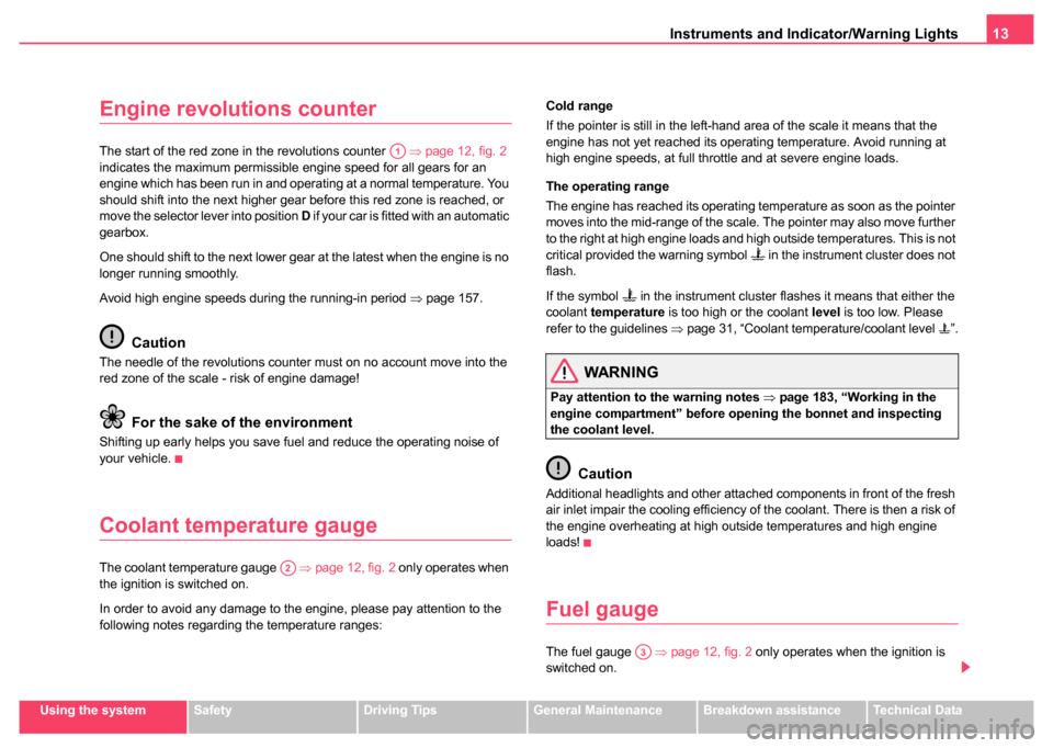
The start of the red zone in the revolutions counter ⇒page 12, fig. 2
indicates the maximum permissible engine speed for all gears for an
engine which has been run in and operating at a normal temperature. You
should shift into the next higher gear before this red zone is reached, or
move the selector lever into position D if your car is fitted with an automatic
gearbox.
One should shift to the next lower gear at the latest when the engine is no
longer running smoothly.
Avoid high engine speeds during the running-in period ⇒page 157.
Caution
The needle of the revolutions counter must on no account move into the
red zone of the scale - risk of engine damage!
For the sake of the environment
Shifting up early helps you save fuel and reduce the operating noise of
your vehicle.
Coolant temperature gauge
The coolant temperature gauge ⇒page 12, fig. 2 only operates when
the ignition is switched on.
In order to avoid any damage to the engine, please pay attention to the
following notes regarding the temperature ranges: Cold range
If the pointer is still in the left-hand area of the scale it means that the
engine has not yet reached its operating temperature. Avoid running at
high engine speeds, at full throttle and at severe engine loads.
The operating range
The engine has reached its operating temperature as soon as the pointer
moves into the mid-range of the scale. The pointer may also move further
to the right at high engine loads and high outside temperatures. This is not
critical provided the warning symbol
in the instrument cluster does not
flash.
If the symbol
in the instrument cluster flashes it means that either the
coolant temperature is too high or the coolant level is too low. Please
refer to the guidelines ⇒page 31, “Coolant temperature/coolant level ”.
WARNING
Pay attention to the warning notes ⇒page 183, “Working in the
engine compartment” before opening the bonnet and inspecting
the coolant level.
Caution
Additional headlights and other attached components in front of the fresh
air inlet impair the cooling efficiency of the coolant. There is then a risk of
the engine overheating at high outside temperatures and high engine
loads!
Fuel gauge
The fuel gauge ⇒page 12, fig. 2 only operates when the ignition is
switched on.
A1
A2
A3
Page 16 of 247
Instruments and Indicator/Warning Lights15
Using the systemSafetyDriving TipsGeneral MaintenanceBreakdown assistanceTechnical Data
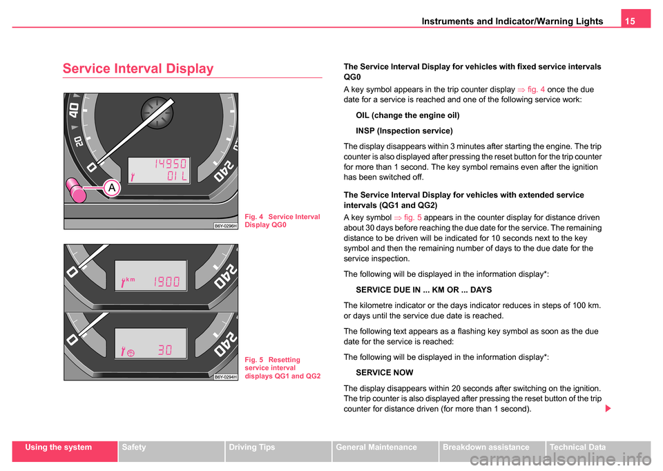
Service Interval DisplayThe Service Interval Display for vehicles with fixed service intervals
QG0
A key symbol appears in the trip counter display ⇒fig. 4 once the due
date for a service is reached and one of the following service work:
OIL (change the engine oil)
INSP (Inspection service)
The display disappears within 3 minutes after starting the engine. The trip
counter is also displayed after pressing the reset button for the trip counter
for more than 1 second. The key symbol remains even after the ignition
has been switched off.
The Service Interval Display for vehicles with extended service
intervals (QG1 and QG2)
A key symbol ⇒ fig. 5 appears in the counter display for distance driven
about 30 days before reaching the due date for the service. The remaining
distance to be driven will be indicated for 10 seconds next to the key
symbol and then the remaining number of days to the due date for the
service inspection.
The following will be displayed in the information display*:
SERVICE DUE IN ... KM OR ... DAYS
The kilometre indicator or the days indicator reduces in steps of 100 km.
or days until the service due date is reached.
The following text appears as a flashing key symbol as soon as the due
date for the service is reached:
The following will be displayed in the information display*: SERVICE NOW
The display disappears within 20 seconds after switching on the ignition.
The trip counter is also displayed after pressing the reset button of the trip
counter for distance driven (for more than 1 second).
Fig. 4 Service Interval
Display QG0
Fig. 5 Resetting
service interval
displays QG1 and QG2
Page 18 of 247
Instruments and Indicator/Warning Lights17
Using the systemSafetyDriving TipsGeneral MaintenanceBreakdown assistanceTechnical Data
Setting minutes
– Turn the reset button to the right.
WARNING
The clock should not be adjusted while driving for safety reasons
but only when the vehicle is stationary.
Multi-functional indicator* (onboard
computer)
Introduction
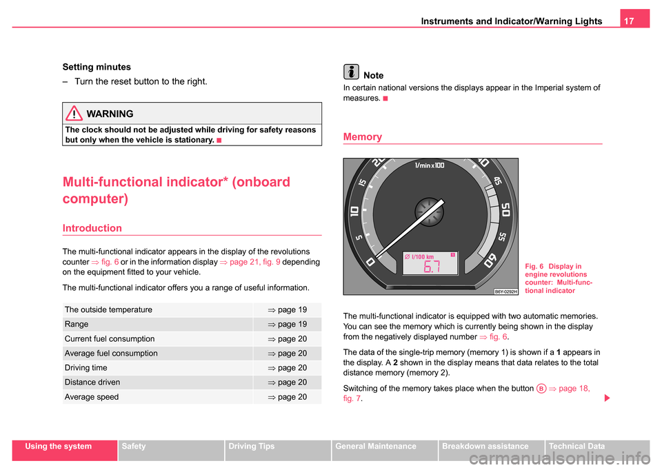
The multi-functional indicator appears in the display of the revolutions
counter ⇒fig. 6 or in the information display ⇒page 21, fig. 9 depending
on the equipment fitted to your vehicle.
The multi-functional indicator offers you a range of useful information.
Note
In certain national versions the displays appear in the Imperial system of
measures.
Memory
The multi-functional indicator is equipped with two automatic memories.
You can see the memory which is currently being shown in the display
from the negatively displayed number ⇒fig. 6 .
The data of the single-trip memory (memory 1) is shown if a 1 appears in
the display. A 2 shown in the display means that data relates to the total
distance memory (memory 2).
Switching of the memory takes place when the button ⇒page 18,
fig. 7 .The outside temperature⇒page 19
Range⇒page 19
Current fuel consumption⇒page 20
Average fuel consumption⇒page 20
Driving time⇒page 20
Distance driven⇒page 20
Average speed⇒page 20
Fig. 6 Display in
engine revolutions
counter: Multi-func-
tional indicator
AB
Page 20 of 247
Instruments and Indicator/Warning Lights19
Using the systemSafetyDriving TipsGeneral MaintenanceBreakdown assistanceTechnical Data
The following readouts of the selected memory will be set to zero by
button :
•Average fuel consumption
•Distance driven
•Average speed
•Driving time
You can only operate the multi-functional indicator when the ignition is
switched on. After the ignition is switched on, the function displayed is the
one which you last selected before switching off the ignition.
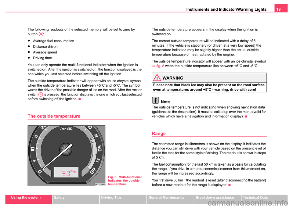
The outside temperature indicator will appear with an ice chrystal symbol
when the outside temperature lies between +5°C and -5°C. The symbol
warns the driver of the possible danger of ice on the road. After the rocker
switch is pressed, the function displays the one which you last selected
before switching off the ignition.
The outside temperature
The outside temperature appears in the display when the ignition is
switched on.
The correct outside temperature will be indicated with a delay of 5
minutes. If the vehicle is stationary (or driven at a very low speed) the
temperature indicated may be slightly higher than the actual outside
temperature because of heat radiated by the engine.
The outside temperature indicator will appear with an ice chrystal symbol
⇒ fig. 8 when the outside temperature lies between +5°C and -5°C.
WARNING
Please note that black ice may also be present on the road surface
even at temperatures around +5°C - warning, drive with care!
Note
The outside temperature is not indicating when showing navigation data
(guidance to the destination). It must be called up over the menu (valid for
vehicles which have a navigation and information display).
Range
The estimated range in kilometres is shown on the display. It indicates the
distance you can still drive with your vehicle based on the present level of
fuel in the tank for the same style of driving. The readout is shown in steps
of 5 km.
The fuel consumption for the last 50 km is taken as a basis for calculating
the range. If you drive in a more economical manner from this moment on,
the range will be increased accordingly.
You first drive 50 km if the readout is reset (after disconnecting the battery)
before a new readout for the range is displayed.
AB
AA
Fig. 8 Multi-functional
indicator: the outside
temperature
Page 22 of 247
Instruments and Indicator/Warning Lights21
Using the systemSafetyDriving TipsGeneral MaintenanceBreakdown assistanceTechnical Data
Information display*
Introduction
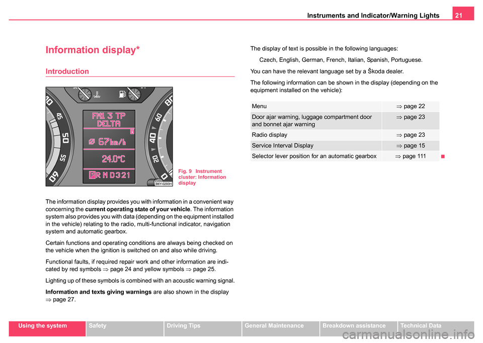
The information display provides you with information in a convenient way
concerning the current operating state of your vehicle . The information
system also provides you with data (depending on the equipment installed
in the vehicle) relating to the radio, multi-functional indicator, navigation
system and automatic gearbox.
Certain functions and operating conditions are always being checked on
the vehicle when the ignition is switched on and also while driving.
Functional faults, if required repair work and other information are indi-
cated by red symbols ⇒page 24 and yellow symbols ⇒page 25.
Lighting up of these symbols is combined with an acoustic warning signal.
Information and texts giving warnings are also shown in the display
⇒ page 27. The display of text is possible in the following languages:
Czech, English, German, French, Italian, Spanish, Portuguese.
You can have the relevant language set by a Škoda dealer.
The following information can be shown in the display (depending on the
equipment installed on the vehicle):
Fig. 9 Instrument
cluster: Information
display
Menu⇒ page 22
Door ajar warning, luggage compartment door
and bonnet ajar warning⇒page 23
Radio display⇒page 23
Service Interval Display⇒page 15
Selector lever position for an automatic gearbox⇒page 111
Page 24 of 247
Instruments and Indicator/Warning Lights23
Using the systemSafetyDriving TipsGeneral MaintenanceBreakdown assistanceTechnical Data
Door ajar warning, luggage compartment door and
bonnet ajar warning
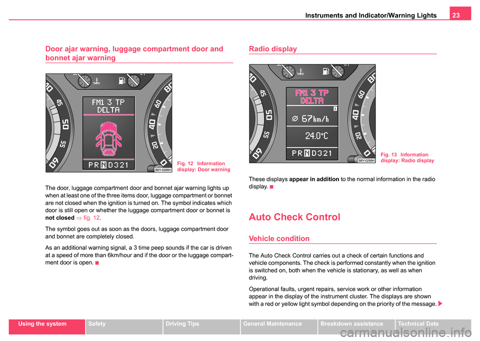
The door, luggage compartment door and bonnet ajar warning lights up
when at least one of the three items door, luggage compartment or bonnet
are not closed when the ignition is turned on. The symbol indicates which
door is still open or whether the luggage compartment door or bonnet is
not closed ⇒ fig. 12 .
The symbol goes out as soon as the doors, luggage compartment door
and bonnet are completely closed.
As an additional warning signal, a 3 time peep sounds if the car is driven
at a speed of more than 6km/hour and if the door or the luggage compart-
ment door is open.
Radio display
These displays appear in addition to the normal information in the radio
display.
Auto Check Control
Vehicle condition
The Auto Check Control carries out a check of certain functions and
vehicle components. The check is performed constantly when the ignition
is switched on, both when the vehicle is stationary, as well as when
driving.
Operational faults, urgent repairs, service work or other information
appear in the display of the instrument cluster. The displays are shown
with a red or yellow light symbol depending on the priority of the message.
Fig. 12 Information
display: Door warning
Fig. 13 Information
display: Radio display