engine SKODA FABIA 2004 1.G / 6Y Owner's Guide
[x] Cancel search | Manufacturer: SKODA, Model Year: 2004, Model line: FABIA, Model: SKODA FABIA 2004 1.G / 6YPages: 247
Page 46 of 247
Unlocking and locking45
Using the systemSafetyDriving TipsGeneral MaintenanceBreakdown assistanceTechnical Data
The boot lid is closed by slamming it closed.
Open the boot lid by pulling on the actuating lever if it is not completely
closed and lift the boot lid right up. Slam the boot lid slightly closed.
Opening the boot lid for vehicles
with a central locking system
Open the boot lid by pressing the hand grip above the licence plate after
unlocking the vehicle using the key or the radio remote control*
⇒ page 44, fig. 26 .
The boot lid can also be opened by pressing on the button on the remote
control with the ignition switched off. Here one should press on the button
for the remote control for over one second. The boot lid springs open and
the anti-theft alarm system* is deactivated. The anti-theft alarm system is
reactivated after the boot lid is closed.
The boot lid is closed by slamming it closed.
Open the boot lid by pulling on the actuating lever if it is not completely
closed and lift the boot lid right up. Slam the boot lid slightly closed.
WARNING
•Ensure that the lock is properly engaged after closing the boot
lid. Otherwise the boot lid could open while driving - risk of acci-
dent!
•Never drive with the boot lid slightly ajar or even fully opened
otherwise exhaust gases may get into the interior of the vehicle -
risk of poisoning!
•Do not press on the rear window when closing the boot lid, it
could crack - risk of injury!
Note
•After closing the boot lid, it is automatically locked within
5 seconds and the anti-theft alarm system* is activated. This applies
only if the vehicle was locked before closing the boot lid.
•The function of the hand grip above the licence plate is deactivated
when starting off or at a speed of more than 5 km/hour for vehicles with
central locking. The function is activated again when the front doors are
opened.
Remote control*
Description
You can use the remote control:
•to unlock and lock the car
•unlocking boot lid
The transmitter with the battery is housed in the handle of the master key.
The receiver is located in the interior of the car. The operating range of the
remote control is 10 metres but this range can be reduced if the batteries
are waek.
The master key has a fold-open key bit which can be used for unlocking
and locking the car manually and also for starting the engine.
If a lost key is replaced or if the receiver unit has been repaired or a new
unit installed, it is then necessary for a Škoda Dealer to initialise the
system. Only after this is it possible to again use the remote control.
Note
•The remote control is automatically deactivated when the ignition is
switched on.
•The operation of the remote control may temporarily be affected by
interference from transmitters close to the car and which operate in the
same frequency range (e.g. mobile phone, TV transmitter).
Page 55 of 247
Lights and Visibility
54
Lights and Visibility
Lights
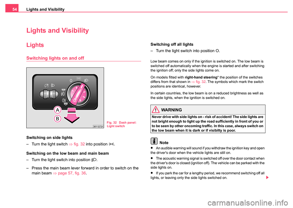
Switching lights on and off
Switching on side lights
– Turn the light switch ⇒fig. 32 into position
.
Switching on the low beam and main beam
– Turn the light switch into position
.
– Press the main beam lever forward in order to switch on the main beam ⇒page 57, fig. 36 . Switching off all lights
– Turn the light switch into position O.
Low beam comes on only if the ignition is switched on. The low beam is
switched off automatically when the engine is started and after switching
the ignition off; only the side lights come on.
On models fitted with
right-hand steering* the position of the switches
differs from that shown in ⇒fig. 32 . The symbols which mark the switch
positions are identical, however.
In certain countries, the low beam is on a reduced brightness as well as
the side lights, when the ignition is switched on.
WARNING
Never drive with side lights on - ri sk of accident! The side lights are
not bright enough to light up the road sufficiently in front of you or
to be seen by other oncoming traffic. In this case, always switch on
the low beam when it is dark or if visibilty is poor.
Note
•An audible warning will sound if you withdraw the ignition key and open
the driver's door when the vehicle lights are still on.
•The acoustic warning signal is switched off over the door contact when
the driver's door is closed (ignition off). The vehicle can be parked with the
side lights on.
•If you park the car for a lengthy period, we recommend switching off all
lights, or leaving only the side lights switched on.
Fig. 32 Dash panel:
Light switch
Page 61 of 247
Lights and Visibility
60
Front door warning light*
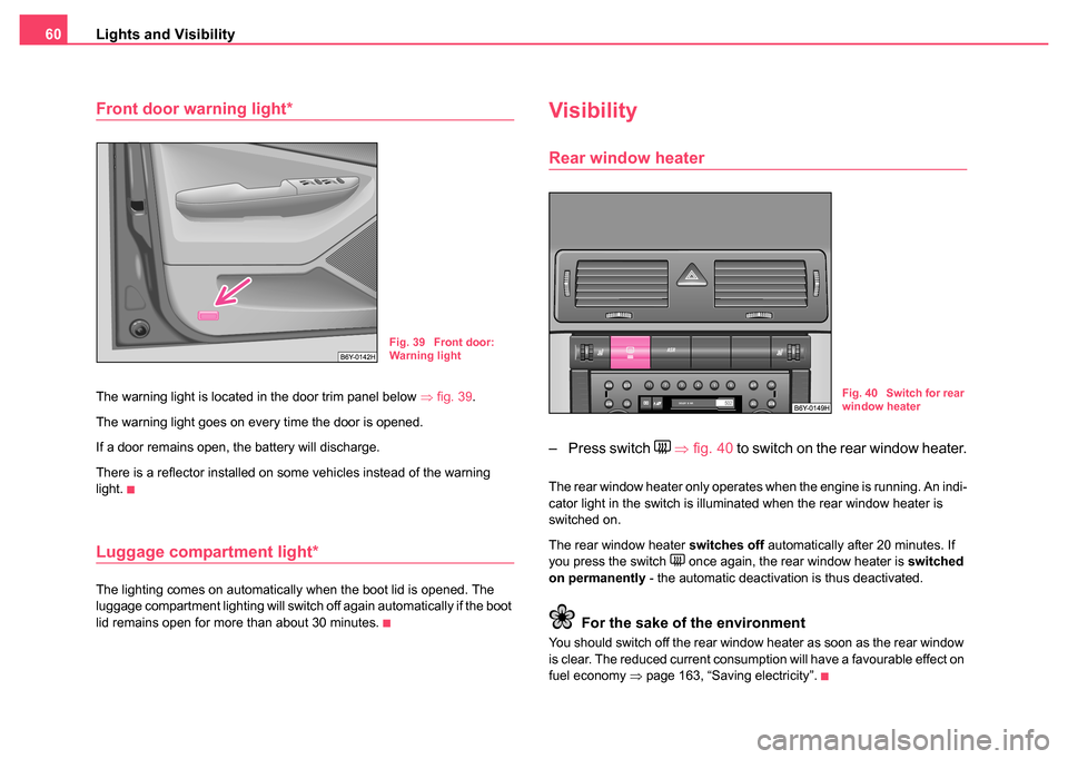
The warning light is located in the door trim panel below ⇒fig. 39 .
The warning light goes on every time the door is opened.
If a door remains open, the battery will discharge.
There is a reflector installed on some vehicles instead of the warning
light.
Luggage compartment light*
The lighting comes on automatically when the boot lid is opened. The
luggage compartment lighting will switch off again automatically if the boot
lid remains open for more than about 30 minutes.
Visibility
Rear window heater
– Press switch ⇒ fig. 40 to switch on the rear window heater.
The rear window heater only operates when the engine is running. An indi-
cator light in the switch is illuminated when the rear window heater is
switched on.
The rear window heater switches off automatically after 20 minutes. If
you press the switch
once again, the rear window heater is switched
on permanently - the automatic deactivation is thus deactivated.
For the sake of the environment
You should switch off the rear window heater as soon as the rear window
is clear. The reduced current consumption will have a favourable effect on
fuel economy ⇒page 163, “Saving electricity”.
Fig. 39 Front door:
Warning light
Fig. 40 Switch for rear
window heater
Page 66 of 247
Lights and Visibility65
Using the systemSafetyDriving TipsGeneral MaintenanceBreakdown assistanceTechnical Data
Rear-view mirror
You can adjust the exterior mirrors electrically*.
Adjust the reverse view mirror before commencing to drive so
that there is a clear view to the rear.
Dimming the interior mirror
– Pull the lever on the bottom edge of the mirror toward rear (the
lever on the interior mirror must point forwards in it home posi-
tion).
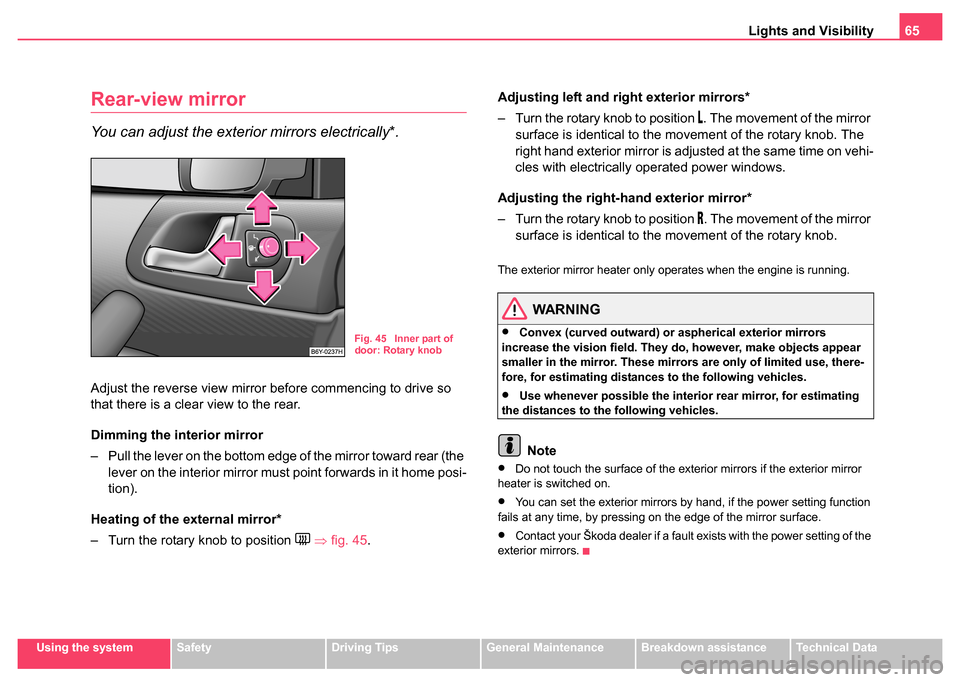
Heating of the external mirror*
– Turn the rotary knob to position
⇒ fig. 45 . Adjusting left and right exterior mirrors*
– Turn the rotary knob to position
. The movement of the mirror
surface is identical to the movement of the rotary knob. The
right hand exterior mirror is adjusted at the same time on vehi-
cles with electrically operated power windows.
Adjusting the right-h and exterior mirror*
– Turn the rotary knob to position
. The movement of the mirror
surface is identical to the movement of the rotary knob.
The exterior mirror heater only operates when the engine is running.
WARNING
•Convex (curved outward) or aspherical exterior mirrors
increase the vision field. They do, however, make objects appear
smaller in the mirror. These mirrors are only of limited use, there-
fore, for estimating distances to the following vehicles.
•Use whenever possible the interior rear mirror, for estimating
the distances to the following vehicles.
Note
•Do not touch the surface of the exterior mirrors if the exterior mirror
heater is switched on.
•You can set the exterior mirrors by hand, if the power setting function
fails at any time, by pressing on the edge of the mirror surface.
•Contact your Škoda dealer if a fault exists with the power setting of the
exterior mirrors.
Fig. 45 Inner part of
door: Rotary knob
Page 71 of 247
Seats and Stowage
70
– The system is switched off by turning the control dial to the home position “0”.
Caution
•You should not kneel on the seats or otherwise apply pressure at
specific points in order to avoid damaging the heating elements of the seat
heaters.
•Do not clean the seats moist ⇒page 175.
Note
The seat heating should only be switched on when the engine is running.
This has a significant effect of saving on the battery capacity.
Rear seats
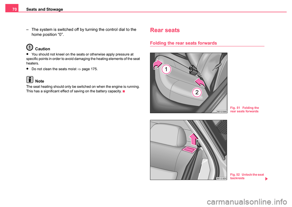
Folding the rear seats forwards
Fig. 51 Folding the
rear seats forwards
Fig. 52 Unlock the seat
backrests
Page 85 of 247
Seats and Stowage
84
Cigarette lighter* and power socket*
Cigarette lighter
You can also use the socket on the cigarette lighter for
other electrical appliances.
Using the cigarette lighter
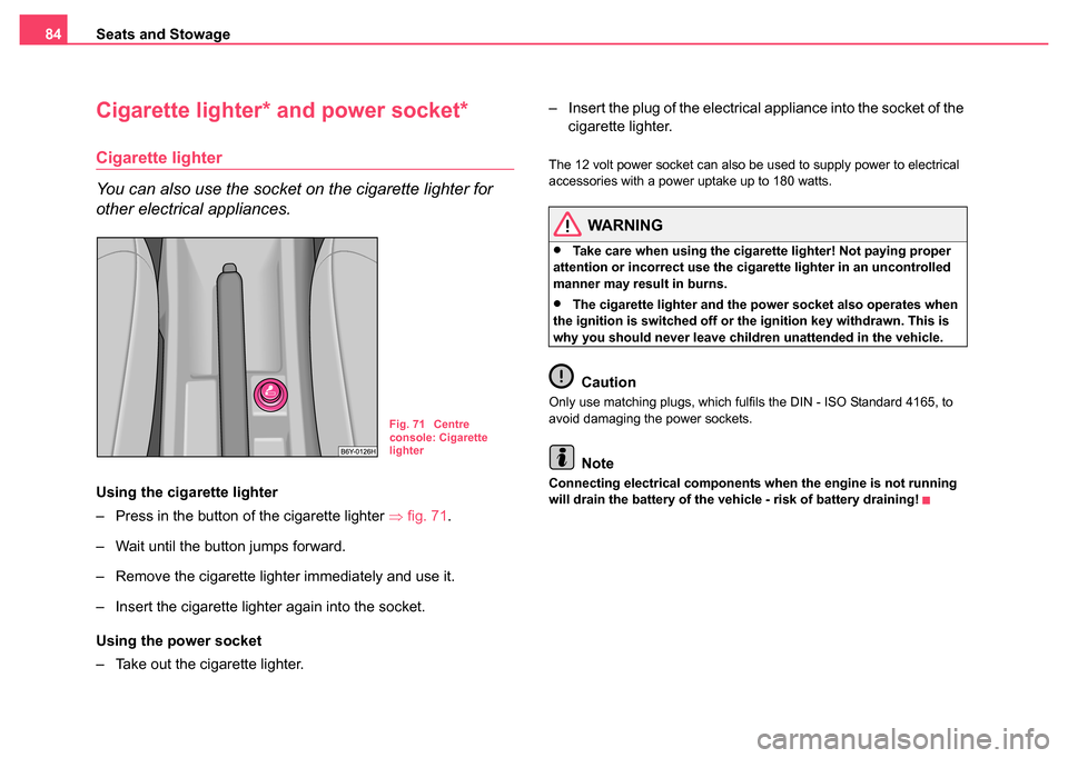
– Press in the button of the cigarette lighter ⇒fig. 71.
– Wait until the button jumps forward.
– Remove the cigarette lighter immediately and use it.
– Insert the cigarette lighter again into the socket.
Using the power socket
– Take out the cigarette lighter. – Insert the plug of the electrical appliance into the socket of the
cigarette lighter.
The 12 volt power socket can also be used to supply power to electrical
accessories with a power uptake up to 180 watts.
WARNING
•Take care when using the cigarette lighter! Not paying proper
attention or incorrect use the cigarette lighter in an uncontrolled
manner may result in burns.
•The cigarette lighter and the power socket also operates when
the ignition is switched off or the ignition key withdrawn. This is
why you should never leave children unattended in the vehicle.
Caution
Only use matching plugs, which fulfils the DIN - ISO Standard 4165, to
avoid damaging the power sockets.
Note
Connecting electrical components when the engine is not running
will drain the battery of the vehicle - risk of battery draining!
Fig. 71 Centre
console: Cigarette
lighter
Page 86 of 247
Seats and Stowage85
Using the systemSafetyDriving TipsGeneral MaintenanceBreakdown assistanceTechnical Data
Power socket in the luggage compartment (Estate
car*, Sedan*)
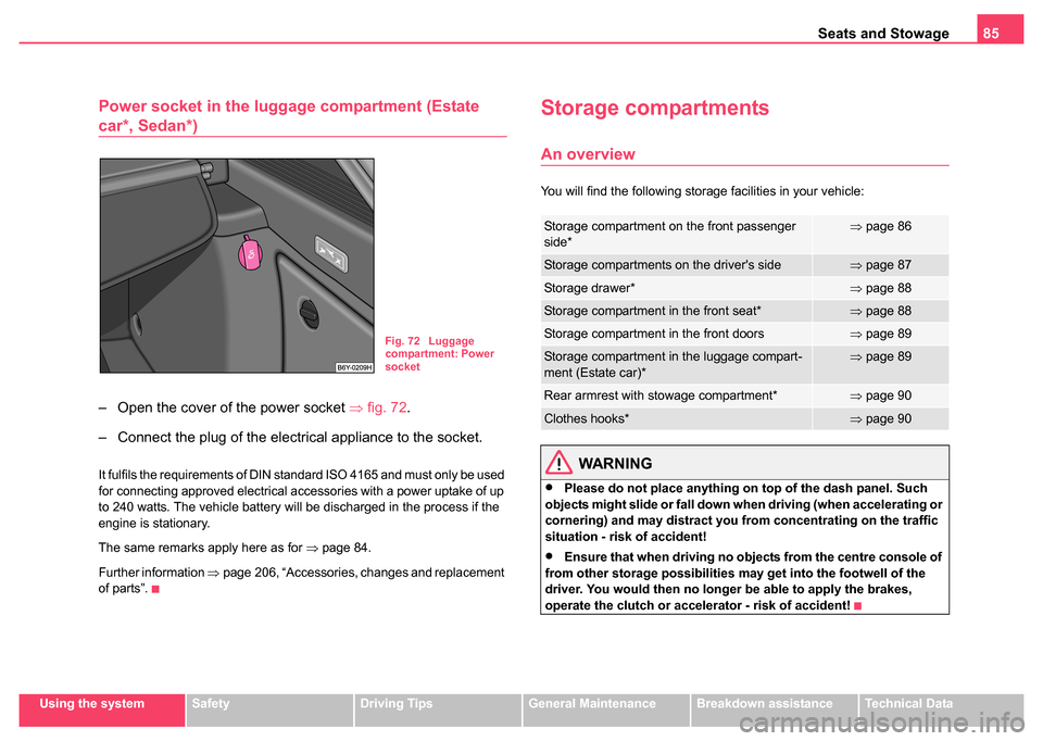
– Open the cover of the power socket ⇒ fig. 72.
– Connect the plug of the electrical appliance to the socket.
It fulfils the requirements of DIN standard ISO 4165 and must only be used
for connecting approved electrical accessories with a power uptake of up
to 240 watts. The vehicle battery will be discharged in the process if the
engine is stationary.
The same remarks apply here as for ⇒page 84.
Further information ⇒page 206, “Accessories, changes and replacement
of parts”.
Storage compartments
An overview
You will find the following storage facilities in your vehicle:
WARNING
•Please do not place anything on top of the dash panel. Such
objects might slide or fall down when driving (when accelerating or
cornering) and may distract you from concentrating on the traffic
situation - risk of accident!
•Ensure that when driving no objects from the centre console of
from other storage possibilities may get into the footwell of the
driver. You would then no longer be able to apply the brakes,
operate the clutch or accelerator - risk of accident!
Fig. 72 Luggage
compartment: Power
socket
Storage compartment on the front passenger
side*⇒ page 86
Storage compartments on the driver's side⇒page 87
Storage drawer*⇒page 88
Storage compartment in the front seat*⇒page 88
Storage compartment in the front doors⇒page 89
Storage compartment in the luggage compart-
ment (Estate car)*⇒page 89
Rear armrest with stowage compartment*⇒page 90
Clothes hooks*⇒page 90
Page 92 of 247
Heating and air conditioning system 91
Using the systemSafetyDriving TipsGeneral MaintenanceBreakdown assistanceTechnical Data
Heating and air conditioning system
Heating
Using the system
The heating system delivers air into the interior of the
vehicle and warms it as required.
Setting temperature
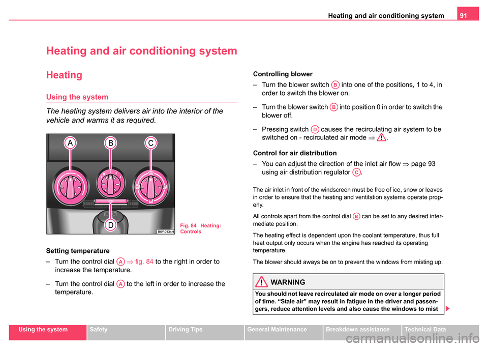
– Turn the control dial ⇒fig. 84 to the right in order to
increase the temperature.
– Turn the control dial to the left in order to increase the temperature. Controlling blower
– Turn the blower switch into one of the positions, 1 to 4, in
order to switch the blower on.
– Turn the blower switch into position 0 in order to switch the blower off.
– Pressing switch causes the recirculating air system to be switched on - recirculated air mode ⇒.
Control for air distribution
– You can adjust the direction of the inlet air flow ⇒page 93
using air distribution regulator .
The air inlet in front of the windscreen must be free of ice, snow or leaves
in order to ensure that the heating and ventilation systems operate prop-
erly.
All controls apart from the control dial can be set to any desired inter-
mediate position.
The heating effect is dependent upon the coolant temperature, thus full
heat output only occurs when the engine has reached its operating
temperature.
The blower should aways be on to prevent the windows from misting up.
WARNING
You should not leave recirculated air mode on over a longer period
of time. “Stale air” may result in fatigue in the driver and passen-
gers, reduce attention levels and also cause the windows to mist
Fig. 84 Heating:
Controls
AA
AA
AB
AB
AD
AC
AB
Page 95 of 247
Heating and air conditioning system
94
You can set the air supply to the individual vents with the air distribution
control ⇒page 91, fig. 84 . Air outlet vents 3 and 4 can also be opened
or closed individually.
Unwarmed or cooled air will flow out of the opened air outlet vents
according to the setting of the control dial ⇒page 91, fig. 84 and
according to atmospheric conditions.
The air conditioning system*
Description
The air conditioning system is a combined cooling and
heating system. It makes it possible to optimally control
the air temperature at any season of the year.
Description of the air conditioning system
It is important for your safety and for your driving comfort that the air condi-
tioning system is operating properly.
The air conditioning system operates when switch ⇒page 95, fig. 86
is pressed and the following conditions are met:
•engine running
•outside temperature above +5 °C
•blower switch switched on (positions 1 to 4)
If the air conditioning system is switched on, the temperature and air
humidity drops in the vehicle. The wellbeing of the occupants of the car is
enhanced as a result of this particularly at high outside temperatures and
a high air humidity. The system prevents the windows misting up during
the cold season of the year. The heating effect is dependent upon the coolant temperature, thus full
heat output only occurs when the engine has reached its operating
temperature.
It is possible to briefly activate recirculated air mode in order to enhance
the cooling effect
⇒.
Air at a temperature of about 5°C may flow out of the vents under certain
circumstances when the air conditioning system is operating. Lengthy and
uneven distribution of the air flow out of the vents (in particular at the leg
area) and large differences in temperature, for example when getting out
of the vehicle, can result in chills in sensitive persons.
The air inlet in front of the windscreen must be free of ice, snow or leaves
in order to ensure that the heating and ventilation systems operate prop-
erly.
After switching on the air conditioning Condensation from the evaporator
of the air conditioning may drip down and form a puddle below the vehicle.
This is quite normal and not an indication of a leak!
WARNING
•For your own safety and that of other road users, ensure that all
the windows are free of ice, snow and misting. Please familiarize
yourself about how to correctly op erate the heating and ventilation
systems, how to demist and defrost the windows, as well as with
the cooling mode.
•You should not leave recirculated air mode on over a longer
period of time. “Stale air” may result in fatigue in the driver and
passengers, reduce attention levels and also cause the windows to
mist up. The risk of having an accident increases. Switch recircu-
lated air mode off as soon as the windows begin misting up.
AC
AA
ACAE
Page 99 of 247
Heating and air conditioning system
98
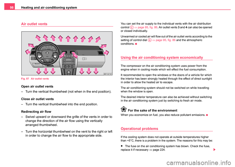
Air outlet vents
Fig. 87 Air outlet vents
Open air outlet vents
– Turn the vertical thumbwheel (not when in the end position).
Close air outlet vents
– Turn the vertical thumbwheel into the end position.
Redirecting air flow
– Swivel upward or downward the gril le of the vents in order to
change the direction of the air flow using the vertically
arranged thumbwheel.
– Turn the horizontal thumbwheel on the vent to the right or left in order to change the air flow to the appropriate side.
You can set the air supply to the individual vents with the air distribution
control ⇒page 95, fig. 86 . Air outlet vents 3 and 4 can also be opened
or closed individually.
Unwarmed or cooled air will flow out of the air outlet vents according to the
setting of control dial ⇒page 95, fig. 86 and the atmospheric
conditions.
Using the air conditioning system economically
The compressor on the air conditioning system uses power from the
engine when in cooling mode which will effect the fuel consumption.
It recommended to open the windows or the doors of a vehicle for which
the interior has been strongly heated through the effect of direct sunlight
in order to allow the heated air to escape.
The air conditioning system should not be switched on while travelling
when the window is open.
The desired interior temperature can also be achieved without switching
in the air conditioning system just by switching to fresh air mode.
For the sake of the environment
When you economize on fuel, you also reduce pollutant emissions.
Operational problems
If the cooling system does not operate at outside temperatures higher
than +5°C, there is a problem in the system. The reasons for this may be:
•The fuse on the air conditioning system has blown. Check the fuse,
replace it if necessary ⇒page 224.
AC
AA