automatic SKODA FABIA 2004 1.G / 6Y Owner's Manual
[x] Cancel search | Manufacturer: SKODA, Model Year: 2004, Model line: FABIA, Model: SKODA FABIA 2004 1.G / 6YPages: 247
Page 6 of 247
Contents5
Contents
Layout of this Owner's Manual
(explanations)
. . . . . . . . . . . . . . . . . . .
Using the system . . . . . . . . . . . . . . .
Cockpit . . . . . . . . . . . . . . . . . . . . . . . . . . . . . . .
An overview . . . . . . . . . . . . . . . . . . . . . . . . . .
Instruments and Indicator/Warning LightsGeneral view of the instrument cluster . . . . . .
Engine revolutions counter . . . . . . . . . . . . . . .
Coolant temperature gauge . . . . . . . . . . . . . .
Fuel gauge . . . . . . . . . . . . . . . . . . . . . . . . . . .
Speedometer with counter for distance driven
Service Interval Display . . . . . . . . . . . . . . . . .
Digital clock . . . . . . . . . . . . . . . . . . . . . . . . . .
Multi-functional indicator* (onboard computer)
Information display* . . . . . . . . . . . . . . . . . . . .
Auto Check Control . . . . . . . . . . . . . . . . . . . .
Warning lights . . . . . . . . . . . . . . . . . . . . . . . . .
Unlocking and locking . . . . . . . . . . . . . . . . . .
Keys . . . . . . . . . . . . . . . . . . . . . . . . . . . . . . . .
Locking . . . . . . . . . . . . . . . . . . . . . . . . . . . . . .
Child safety locks . . . . . . . . . . . . . . . . . . . . . .
Central locking system* . . . . . . . . . . . . . . . . .
Remote control* . . . . . . . . . . . . . . . . . . . . . . .
Anti-theft alarm system* . . . . . . . . . . . . . . . . .
Power windows* . . . . . . . . . . . . . . . . . . . . . . .
Electric sliding/tilting roof* . . . . . . . . . . . . . . .
Lights and Visibility. . . . . . . . . . . . . . . . . . . . .
Lights . . . . . . . . . . . . . . . . . . . . . . . . . . . . . . .
Interior lighting . . . . . . . . . . . . . . . . . . . . . . . .
Visibility . . . . . . . . . . . . . . . . . . . . . . . . . . . . . The windscreen wiper and washing system .
Rear-view mirror . . . . . . . . . . . . . . . . . . . . . .
Seats and Stowage . . . . . . . . . . . . . . . . . . . .
Front seats . . . . . . . . . . . . . . . . . . . . . . . . . . .
Head restraints . . . . . . . . . . . . . . . . . . . . . . . .
Middle rear head restraint* . . . . . . . . . . . . . . .
Heating the front seats* . . . . . . . . . . . . . . . . .
Rear seats . . . . . . . . . . . . . . . . . . . . . . . . . . .
Pedals . . . . . . . . . . . . . . . . . . . . . . . . . . . . . .
Luggage compartment . . . . . . . . . . . . . . . . . .
Net partition (Estate)* . . . . . . . . . . . . . . . . . . .
The roof luggage rack system* . . . . . . . . . . .
Drinks can holder* . . . . . . . . . . . . . . . . . . . . .
Note holder . . . . . . . . . . . . . . . . . . . . . . . . . .
Ashtray at the front* . . . . . . . . . . . . . . . . . . . .
Ashtray at the rear* . . . . . . . . . . . . . . . . . . . .
Cigarette lighter* and power socket* . . . . . . .
Storage compartments . . . . . . . . . . . . . . . . . .
Heating and air conditioning system . . . . .
Heating . . . . . . . . . . . . . . . . . . . . . . . . . . . . . .
The air conditioning system* . . . . . . . . . . . . .
Starting-off and Driving. . . . . . . . . . . . . . . . .
Setting steering wheel position* . . . . . . . . . . .
Ignition lock . . . . . . . . . . . . . . . . . . . . . . . . . .
Starting engine . . . . . . . . . . . . . . . . . . . . . . . .
Switching the engine off . . . . . . . . . . . . . . . . .
Shifting (manual gearbox) . . . . . . . . . . . . . . .
Handbrake . . . . . . . . . . . . . . . . . . . . . . . . . . .
Parking aid* . . . . . . . . . . . . . . . . . . . . . . . . . .
Cruise control system (CCS)* . . . . . . . . . . . .
Automatic gearbox*. . . . . . . . . . . . . . . . . . . .
4-speed automatic gearbox . . . . . . . . . . . . . .
Communication . . . . . . . . . . . . . . . . . . . . . . .
Universal telephone connection* . . . . . . . . . .
Mobile phones and two-way radio systems . .
The CD changer* . . . . . . . . . . . . . . . . . . . . . .
Safety. . . . . . . . . . . . . . . . . . . . . . . . . . . . . .
Passive Safety . . . . . . . . . . . . . . . . . . . . . . . .
Basic information . . . . . . . . . . . . . . . . . . . . . .
Correct seated position . . . . . . . . . . . . . . . . .
Seat belts. . . . . . . . . . . . . . . . . . . . . . . . . . . . .
Why seat belts? . . . . . . . . . . . . . . . . . . . . . . .
The physical principle of a frontal collision . .
Important safety information regarding the use
of seat belts . . . . . . . . . . . . . . . . . . . . . . . . . .
How are seat belts correctly fastened? . . . . .
Belt tensioners . . . . . . . . . . . . . . . . . . . . . . . .
Airbag system. . . . . . . . . . . . . . . . . . . . . . . . .
Description of the airbag system . . . . . . . . . .
Front airbags . . . . . . . . . . . . . . . . . . . . . . . . .
Side airbags* . . . . . . . . . . . . . . . . . . . . . . . . .
Deactivating an airbag . . . . . . . . . . . . . . . . . .
Transporting children safely . . . . . . . . . . . .
What you should know about transporting
children! . . . . . . . . . . . . . . . . . . . . . . . . . . . . .
Child seat . . . . . . . . . . . . . . . . . . . . . . . . . . . .
Attaching a child seat using the “ISOFIX”*
system . . . . . . . . . . . . . . . . . . . . . . . . . . . . . .
8
9
11
11
12
12
13
13
13
14
15
16
17
21
23
27
37
37
39
40
40
45
48
49
51
54
54
58
60 61
65
66
66
68
69
69
70
72
72
77
80
82
82
83
83
84
85
91
91
94
100
100
101
102
103
104
105
106
107 11 0
11 0 11 5
11 5
11 6
11 6
11 7
11 7
11 7
11 9
123
123
124
125
126
129
130
130
132
134
137
140
140
144
148
Page 12 of 247
Cockpit11
Using the systemSafetyDriving TipsGeneral MaintenanceBreakdown assistanceTechnical Data
Cockpit
An overview
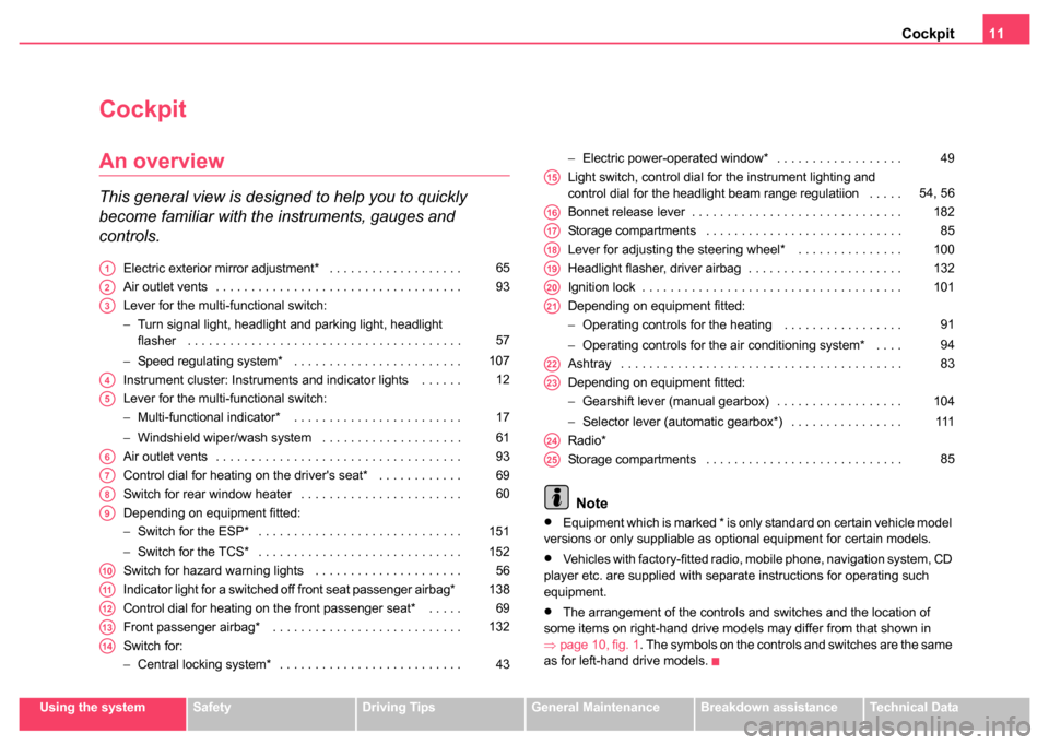
This general view is designed to help you to quickly
become familiar with the instruments, gauges and
controls.
Electric exterior mirror adjustment* . . . . . . . . . . . . . . . . . . .
Air outlet vents . . . . . . . . . . . . . . . . . . . . . . . . . . . . . . . . . . .
Lever for the multi-functional switch:
−Turn signal light, headlight and parking light, headlight
flasher . . . . . . . . . . . . . . . . . . . . . . . . . . . . . . . . . . . . . . .
− Speed regulating system* . . . . . . . . . . . . . . . . . . . . . . . .
Instrument cluster: Instruments and indicator lights . . . . . .
Lever for the multi-functional switch:
− Multi-functional indicator* . . . . . . . . . . . . . . . . . . . . . . . .
− Windshield wiper/wash system . . . . . . . . . . . . . . . . . . . .
Air outlet vents . . . . . . . . . . . . . . . . . . . . . . . . . . . . . . . . . . .
Control dial for heating on the driver's seat* . . . . . . . . . . . .
Switch for rear window heater . . . . . . . . . . . . . . . . . . . . . . .
Depending on equipment fitted:
− Switch for the ESP* . . . . . . . . . . . . . . . . . . . . . . . . . . . . .
− Switch for the TCS* . . . . . . . . . . . . . . . . . . . . . . . . . . . . .
Switch for hazard warning lights . . . . . . . . . . . . . . . . . . . . .
Indicator light for a switched off front seat passenger airbag*
Control dial for heating on the front passenger seat* . . . . .
Front passenger airbag* . . . . . . . . . . . . . . . . . . . . . . . . . . .
Switch for:
− Central locking system* . . . . . . . . . . . . . . . . . . . . . . . . . . −
Electric power-operated window* . . . . . . . . . . . . . . . . . .
Light switch, control dial for the instrument lighting and
control dial for the headlight beam range regulatiion . . . . .
Bonnet release lever . . . . . . . . . . . . . . . . . . . . . . . . . . . . . .
Storage compartments . . . . . . . . . . . . . . . . . . . . . . . . . . . .
Lever for adjusting the steering wheel* . . . . . . . . . . . . . . .
Headlight flasher, driver airbag . . . . . . . . . . . . . . . . . . . . . .
Ignition lock . . . . . . . . . . . . . . . . . . . . . . . . . . . . . . . . . . . . .
Depending on equipment fitted:
− Operating controls for the heating . . . . . . . . . . . . . . . . .
− Operating controls for the air conditioning system* . . . .
Ashtray . . . . . . . . . . . . . . . . . . . . . . . . . . . . . . . . . . . . . . . .
Depending on equipment fitted:
− Gearshift lever (manual gearbox) . . . . . . . . . . . . . . . . . .
− Selector lever (automatic gearbox*) . . . . . . . . . . . . . . . .
Radio*
Storage compartments . . . . . . . . . . . . . . . . . . . . . . . . . . . .
Note
•Equipment which is marked * is only standard on certain vehicle model
versions or only suppliable as optional equipment for certain models.
•Vehicles with factory-fitted radio, mobile phone, navigation system, CD
player etc. are supplied with separate instructions for operating such
equipment.
•The arrangement of the controls and switches and the location of
some items on right-hand drive models may differ from that shown in
⇒ page 10, fig. 1 . The symbols on the controls and switches are the same
as for left-hand drive models.
A165
A293
A3
57
107
A412
A5
17
61
A693
A769
A860
A9
151
152
A1056
A11138
A1269
A13132
A14
43 49
A1554, 56
A16182
A1785
A18100
A19132
A20101
A21
91
94
A2283
A23
104
111
A24
A2585
Page 14 of 247
Instruments and Indicator/Warning Lights13
Using the systemSafetyDriving TipsGeneral MaintenanceBreakdown assistanceTechnical Data
Engine revolutions counter
The start of the red zone in the revolutions counter ⇒page 12, fig. 2
indicates the maximum permissible engine speed for all gears for an
engine which has been run in and operating at a normal temperature. You
should shift into the next higher gear before this red zone is reached, or
move the selector lever into position D if your car is fitted with an automatic
gearbox.
One should shift to the next lower gear at the latest when the engine is no
longer running smoothly.
Avoid high engine speeds during the running-in period ⇒page 157.
Caution
The needle of the revolutions counter must on no account move into the
red zone of the scale - risk of engine damage!
For the sake of the environment
Shifting up early helps you save fuel and reduce the operating noise of
your vehicle.
Coolant temperature gauge
The coolant temperature gauge ⇒page 12, fig. 2 only operates when
the ignition is switched on.
In order to avoid any damage to the engine, please pay attention to the
following notes regarding the temperature ranges: Cold range
If the pointer is still in the left-hand area of the scale it means that the
engine has not yet reached its operating temperature. Avoid running at
high engine speeds, at full throttle and at severe engine loads.
The operating range
The engine has reached its operating temperature as soon as the pointer
moves into the mid-range of the scale. The pointer may also move further
to the right at high engine loads and high outside temperatures. This is not
critical provided the warning symbol
in the instrument cluster does not
flash.
If the symbol
in the instrument cluster flashes it means that either the
coolant temperature is too high or the coolant level is too low. Please
refer to the guidelines ⇒page 31, “Coolant temperature/coolant level ”.
WARNING
Pay attention to the warning notes ⇒page 183, “Working in the
engine compartment” before opening the bonnet and inspecting
the coolant level.
Caution
Additional headlights and other attached components in front of the fresh
air inlet impair the cooling efficiency of the coolant. There is then a risk of
the engine overheating at high outside temperatures and high engine
loads!
Fuel gauge
The fuel gauge ⇒page 12, fig. 2 only operates when the ignition is
switched on.
A1
A2
A3
Page 18 of 247
Instruments and Indicator/Warning Lights17
Using the systemSafetyDriving TipsGeneral MaintenanceBreakdown assistanceTechnical Data
Setting minutes
– Turn the reset button to the right.
WARNING
The clock should not be adjusted while driving for safety reasons
but only when the vehicle is stationary.
Multi-functional indicator* (onboard
computer)
Introduction
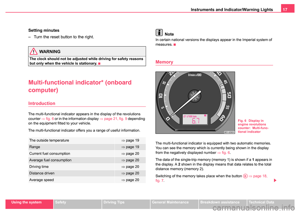
The multi-functional indicator appears in the display of the revolutions
counter ⇒fig. 6 or in the information display ⇒page 21, fig. 9 depending
on the equipment fitted to your vehicle.
The multi-functional indicator offers you a range of useful information.
Note
In certain national versions the displays appear in the Imperial system of
measures.
Memory
The multi-functional indicator is equipped with two automatic memories.
You can see the memory which is currently being shown in the display
from the negatively displayed number ⇒fig. 6 .
The data of the single-trip memory (memory 1) is shown if a 1 appears in
the display. A 2 shown in the display means that data relates to the total
distance memory (memory 2).
Switching of the memory takes place when the button ⇒page 18,
fig. 7 .The outside temperature⇒page 19
Range⇒page 19
Current fuel consumption⇒page 20
Average fuel consumption⇒page 20
Driving time⇒page 20
Distance driven⇒page 20
Average speed⇒page 20
Fig. 6 Display in
engine revolutions
counter: Multi-func-
tional indicator
AB
Page 22 of 247
Instruments and Indicator/Warning Lights21
Using the systemSafetyDriving TipsGeneral MaintenanceBreakdown assistanceTechnical Data
Information display*
Introduction
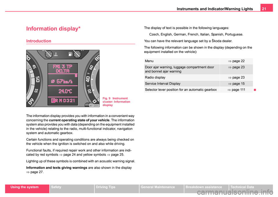
The information display provides you with information in a convenient way
concerning the current operating state of your vehicle . The information
system also provides you with data (depending on the equipment installed
in the vehicle) relating to the radio, multi-functional indicator, navigation
system and automatic gearbox.
Certain functions and operating conditions are always being checked on
the vehicle when the ignition is switched on and also while driving.
Functional faults, if required repair work and other information are indi-
cated by red symbols ⇒page 24 and yellow symbols ⇒page 25.
Lighting up of these symbols is combined with an acoustic warning signal.
Information and texts giving warnings are also shown in the display
⇒ page 27. The display of text is possible in the following languages:
Czech, English, German, French, Italian, Spanish, Portuguese.
You can have the relevant language set by a Škoda dealer.
The following information can be shown in the display (depending on the
equipment installed on the vehicle):
Fig. 9 Instrument
cluster: Information
display
Menu⇒ page 22
Door ajar warning, luggage compartment door
and bonnet ajar warning⇒page 23
Radio display⇒page 23
Service Interval Display⇒page 15
Selector lever position for an automatic gearbox⇒page 111
Page 25 of 247
Instruments and Indicator/Warning Lights
24
The red symbols indicate danger (priority 1) while the yellow symbols indi-
cate a warning (priortity 2). Information for the driver may also appear in
addition to the symbols ⇒page 27.
Investigate the displayed faults as soon as possible. If several operational
faults exist at the same time, the symbols will appear one after the other
and are each visible for about 2 seconds.
The error messages are faded out after 10 seconds or by actuating the
rocker switch ⇒page 22, fig. 11 and are stored under the information
CAR STATUS.
There is at least one error message to be read when the term CAR
STATUS is flashing in the main menu. The display will show STATUS 1/2
(for example) if a number of error messages are present. This display indi-
cates that the first of a total of two error messages should be displayed.
Actuate the rocker switch , to call up the individual error messages.
If a fault occurs, a warning signal will also sound in addition to the symbol
and text in the display:
•Priority 1 - three warning signals
•Priority 2 - one warning signal
Operational check of the automatic gearbox
When the ignition is switched on, the Auto Check Control automatically
carries out an operational check. The following text will appear first in the
display if the selector lever is the position P or N:
P LOCKED
or N LOCKED You must depress the brake pedal first and press the Shiftlock button at
the same time in order to move the selector lever out of these positions.
The text will disappear once you select a drive position (
R, D etc.), and the
Auto Check Control function is displayed.
If the Auto Check Control detects faults, these will be displayed about 15
seconds after starting the engine in place of the text shown above. A
warning signal sounds at the same time.
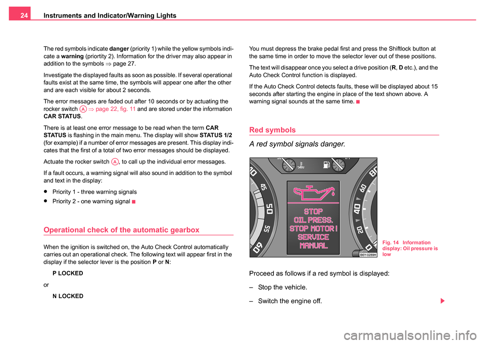
Red symbols
A red symbol signals danger.
Proceed as follows if a red symbol is displayed:
– Stop the vehicle.
– Switch the engine off.
AA
AA
Fig. 14 Information
display: Oil pressure is
low
Page 32 of 247
Instruments and Indicator/Warning Lights31
Using the systemSafetyDriving TipsGeneral MaintenanceBreakdown assistanceTechnical Data
Coolant temperature/coolant level
The warning light comes on for a few seconds 1) when the ignition is
switched on.
The coolant temperature is too high or the coolant level too low if the
warning light
does not go out after the engine is started or flashes while
driving.
3 peeps sound as an additional warning signal.
In this case stop and switch the engine off and check the coolant level;
top up the coolant as necessary.
Do not continue your journey if for some reason it is not possible under
the conditions prevailing to top up with coolant. Keep the engine
switched off and obtain professional assistance from a Škoda dealer.
If the coolant is within the specified range, the increased temperature may
be caused by an operating problem at the coolant fan. Check the fuse for
the coolant fan, replace it if necessary ⇒page 225, “Fuse assignment at
battery”.
Do not continue driving if the warning light does not go off although the
fluid is at the correct level and also the fuse of the fan is in proper order.
Contact a Škoda dealer to obtain assistance.
Please also refer to the additional instructions ⇒page 189, “Cooling
system”.
The following text will be displayed in the information display*:
STOP CHECK COOLANT SERVICE MANUAL
WARNING
•Take care when opening the coolant expansion bottle. If the
engine is hot, the cooling system is pressurized - risk of scalding.
It is best to allow the engine to cool down before removing the cap.
•Do not touch the coolant fan The coolant fan may switch on
automatically even if the ignition is off.
Electronic immobiliser
Data is compared between the ignition key and the control unit when
switching on the ignition. The indicator light will light up for a few
seconds when ignition key authorisation is confirmed.
The warning light will start flashing continuously if a non-authorised igni-
tion key (for example the wrong ignition key) has been used. The engine
cannot be started ⇒page 39.
It is only possible to start the engine of the vehicle with a Genuine Škoda
key with the matching code.
Fuel reserve
The warning light comes on, if the fuel level is still about 7 litres.
A peep sounds as an additional warning signal.
The following text will be displayed in the information display*: PLEASE REFUEL
1)The warning light on vehicles fitted with information display does not come on
after switching the ignition on, but only if the coolant temperature is to\
o high or the
coolant level is too low.
Page 35 of 247
Instruments and Indicator/Warning Lights
34
The fact that the TCS system operates together with the ABS means that
the TCS warning light will also come on if the ABS system is not operating
properly.
Further information about the TCS ⇒page 152, “Traction control system
(TCS)*”.
Electronic Stability Programme (ESP)*
The warning light comes on for a few seconds when the ignition is
switched on.
Components of the ESP system also include the Traction Control System
(TCS), Electronic Differential Lock (EDL), and the Antilock Brake System
ABS (ABS).
The warning light comes on when driving when a control cycle is acti-
vated.
The warning lig ht will come on an d remains on if the ESP is switched off
or if there is a fault in the system.
The fact that the ESP system operates together with the ABS means that
the ESP warning light will also come on if the ABS system is not operating
properly.
Further information on the ESP ⇒page 151, “Electronic stability
programme (ESP)*”.
Antilock brake system (ABS)*
The warning light shows the functionality of the ABS and the Electronic
Differential Lock (EDL). The warning light comes on for a few seconds after the ignition has been
switched on or when starting the engine. The warning light goes out after
an automatic check sequence has been completed.
A fault in the ABS
The system is not functioning properly if the ABS warning light
does
not go out within a few seconds after switching on the ignition, does not
light up at all or lights up while driving. The vehicle will only be braked by
the normal brake system without the effect of the ABS function. Visit a
Škoda dealer as quickly as possible and adjust your style of driving in the
meantime since you will not know how great the damage is.
Three additional warning tones will sound if there is a major fault in the
ABS.
Further information about ABS ⇒page 155, “Antilock brake system
(ABS)*”.
A fault in the entire brake system
If the ABS warning light
comes on together with the brake system
warning light (handbrake must be released), there is a fault not only in
the ABS but also in another part of the brake system ⇒.
The following text will be displayed in the information display*: STOP BRAKE FAULT SERVICE MANUAL
Electronic Differential Lock (EDL)*
The EDL is a part of the ABS. A fault in the EDL is indicated by the ABS
warning light
in the instrument cluster. Have the vehicle inspected
without delay by a Škoda dealer. Further information on the EDL
⇒ page 153.
WARNING
•If the brake system warning light comes on together with the
ABS warning light stop the vehicle immediately and check the
Page 40 of 247
Unlocking and locking39
Using the systemSafetyDriving TipsGeneral MaintenanceBreakdown assistanceTechnical Data
dealer. You should, however, proceed as follows if you wish to
replace the battery yourself:
– Fold open the key.
– Use a screwdriver to carefully lever off the front part of the key
⇒ page 38, fig. 19 from the transmitter housing .
– Take off the cover of the transmitter housing ⇒page 38,
fig. 20 in direction of arrow.
– Take the used battery out of the housing cover.
– Insert the new battery. Ensure that the “+” symbol on the battery is facing downwards. The correct polarity is also
shown on the cover of the transmitter housing.
– Insert cover with battery in place at the rear of the transmitter housing and press both parts together.
– Insert the transmitter housing into the front part of the key so that the two parts lock into each other.
For the sake of the environment
Dispose of an old battery in accordance with environmental regulations.
Note
•The replacement battery must have the same specification as the orig-
inal battery.
•If it is still not be possible to unlock or lock the vehicle with the remote
control even after replacing the battery this means that the system has to
be synchronised ⇒page 47.
Electronic immobiliser
The electronic immobiliser prevents the vehicle being
operated by an unauthorised person.
An electronic chip is integrated in the head of the key. The immobiliser is
deactivated with the aid of this chip when the key is inserted in the ignition
lock. The electronic immobiliser is automatically activated when you with-
draw the ignition key from the lock.
Note
It is only possible to start the engine of your car with a Genuine Škoda key
with the matching code ⇒page 31.
Locking
Valid for vehicles without a central locking system:
Locking from outside
The securing head will move upwards or downwards in the door when
unlocking or locking ⇒page 43, fig. 23 .
Locking from inside
All closed vehicle doors are locked by pressing in the securing knobs from
the inside. The doors cannot be opened from the outside when the
securing knobs have been pressed in. The vehicle doors can be opened
from the inside as follows:
•The door is unlocked by actuating the door-opening lever.
•The door opens upon actuating the door-opening lever again.
AAAB
AA
Page 42 of 247
Unlocking and locking41
Using the systemSafetyDriving TipsGeneral MaintenanceBreakdown assistanceTechnical Data
Convenience operation of windows
One can open and close the electrically powered windows when opening
and closing the vehicle
⇒page 50, “Convenience operation of windows”.
Opening a single door*
This function allows one to just unlock the driver's door. The other doors
remain locked and are only unlocked when the command is repeated.
The single door opening function can be first activated by recoding the
control unit of the central locking system. This work is undertaken by a
Škoda dealer which can give you more information.
Automatic locking*
All the doors and the boot lid are locked automatically once the car
reaches a speed of about 15 km/h.
If the ignition key is withdrawn, the car is then automatically unlocked
again. In addition, it is possible for the driver to unlock the car by pressing
the central locking button
or by pulling the door opening lever.
If you wish, your Škoda Dealer can convert the central locking system of
your car to the automatic locking mode.
WARNING
•Locking the doors prevents involuntary opening in an excep-
tional situation (an accident). Locked doors prevent unwanted
entry into the vehicle from outside, for example at road crossings.
Locked doors do, however, make it more difficult for rescuers to
get into the vehicle in an emergency - danger to life!
Note
•After locking the vehicle see, if the securing knobs located on the front
doors are pushed down. On vehicles with central locking the rear doors
have no securing knobs.
•In the event of an accident in which the airbags are deployed, the
locked doors are automatically unlocked in order to enable rescuers to
gain access to the vehicle.
•Only the front doors can be unlocked and locked using the key if the
central locking system fails. You can operate the rear door manually.
−Emergency locking of the door ⇒page 44.
Safe securing
The central locking system is equipped with a safe securing system.
Locking the vehicle from the outside causes the door locks to be automat-
ically blocked. It is not possible to pull out the locking buttons. The indi-
cator light in the driver's door flashes. It is not possible to open the doors
with the door handle either from the inside or from the outside. This acts
as an effective deterrent for attempts to break into your vehicle.
You can deactivate the safe securing system. This is done by locking the
vehicle with the key or radio-operated key twice within 2 seconds.
Deactivating the safe securing system means that the warning light next
to the securing knob in the driver's door ⇒page 43, fig. 23 will not
flash. This is not the case, however, for an activated anti-theft alarm
system* since the indicator light is showing that the system is active.
The safe securing system is again activated the next time the vehicle is
unlocked and locked again.
The doors can be opened from the inside if the vehicle is locked and the
safe securing system is deactivated:
•The door is unlocked by actuating the door-opening lever.
•The door opens upon actuating the door-opening lever again.
AA