engine SKODA FABIA 2005 1.G / 6Y Owner's Manual
[x] Cancel search | Manufacturer: SKODA, Model Year: 2005, Model line: FABIA, Model: SKODA FABIA 2005 1.G / 6YPages: 260
Page 2 of 260
Introduction
You have opted for a Škoda - our sincere thanks for your confidence in us.
Your new Škoda offers you a vehicle featuring the most modern engineering and a wide range of equipment
which you will undoubtedly wish to use to the full during your daily motoring. That is why, we recommend
that you read this Owner's Manual attentively to enable you to become familiar with your car and all that it
offers as quickly as possible.
Please do not hesitate to contact your Škoda dealer or importer should you have any further questions
regarding any problems which may arise or your vehicle. He will be ready at any time to receive your ques-
tions, suggestions and criticisms.
Any national legal provisions which vary from the information contained in this Owner's Manual take prec-
edence over the information contained herein.
We wish you much pleasure with your Škoda and pleasant motoring at all times.
Your Škoda Auto
sqc.1.book Seite 1 Mittwoch, 13. April 2005 1:09 13
Page 6 of 260
Contents5
Contents
Layout of this Owner's Manual
(explanations)
. . . . . . . . . . . . . . . . . . .
Using the system . . . . . . . . . . . . . . .
Cockpit . . . . . . . . . . . . . . . . . . . . . . . . . . . . . . .
An overview . . . . . . . . . . . . . . . . . . . . . . . . . .
Instruments and Indicator/Warning LightsGeneral view of the instrument cluster . . . . . .
Engine revolutions counter . . . . . . . . . . . . . . .
Coolant temperature gauge . . . . . . . . . . . . . .
Fuel gauge . . . . . . . . . . . . . . . . . . . . . . . . . . .
Speedometer with counter for distance driven
Service Interval Display . . . . . . . . . . . . . . . . .
Digital clock . . . . . . . . . . . . . . . . . . . . . . . . . .
Multi-functional indicator* (onboard computer)
Information display* . . . . . . . . . . . . . . . . . . . .
Auto Check Control . . . . . . . . . . . . . . . . . . . .
Warning lights . . . . . . . . . . . . . . . . . . . . . . . . .
Unlocking and locking . . . . . . . . . . . . . . . . . .
Keys . . . . . . . . . . . . . . . . . . . . . . . . . . . . . . . .
Locking . . . . . . . . . . . . . . . . . . . . . . . . . . . . . .
Child safety locks . . . . . . . . . . . . . . . . . . . . . .
Central locking system* . . . . . . . . . . . . . . . . .
Remote control* . . . . . . . . . . . . . . . . . . . . . . .
Anti-theft alarm system* . . . . . . . . . . . . . . . . .
Power windows* . . . . . . . . . . . . . . . . . . . . . . .
Electric sliding/tilting roof* . . . . . . . . . . . . . . .
Lights and Visibility. . . . . . . . . . . . . . . . . . . . .
Lights . . . . . . . . . . . . . . . . . . . . . . . . . . . . . . .
Interior lighting . . . . . . . . . . . . . . . . . . . . . . . .
Visibility . . . . . . . . . . . . . . . . . . . . . . . . . . . . . Windshield wiper and wash system . . . . . . . .
Rear-view mirror . . . . . . . . . . . . . . . . . . . . . .
Seats and Stowage . . . . . . . . . . . . . . . . . . . .
Front seats . . . . . . . . . . . . . . . . . . . . . . . . . . .
Head restraints . . . . . . . . . . . . . . . . . . . . . . . .
Middle rear head restraint* . . . . . . . . . . . . . . .
Heating the front seats* . . . . . . . . . . . . . . . . .
Rear seats . . . . . . . . . . . . . . . . . . . . . . . . . . .
Pedals . . . . . . . . . . . . . . . . . . . . . . . . . . . . . .
Luggage compartment . . . . . . . . . . . . . . . . . .
Net partition (Estate)* . . . . . . . . . . . . . . . . . . .
The roof luggage rack system* . . . . . . . . . . .
Drinks can holder* . . . . . . . . . . . . . . . . . . . . .
Rear drinks can holder * . . . . . . . . . . . . . . . .
Note holder . . . . . . . . . . . . . . . . . . . . . . . . . .
Ashtray at the front* . . . . . . . . . . . . . . . . . . . .
Ashtray at the rear* . . . . . . . . . . . . . . . . . . . .
Cigarette lighter* and power socket* . . . . . . .
Storage compartments . . . . . . . . . . . . . . . . . .
Heating and air conditioning system . . . . .
Heating . . . . . . . . . . . . . . . . . . . . . . . . . . . . . .
The air conditioning system* . . . . . . . . . . . . .
Starting-off and Driving. . . . . . . . . . . . . . . . .
Setting steering wheel position* . . . . . . . . . . .
Ignition lock . . . . . . . . . . . . . . . . . . . . . . . . . .
Starting engine . . . . . . . . . . . . . . . . . . . . . . . .
Switching the engine off . . . . . . . . . . . . . . . . .
Shifting (manual gearbox) . . . . . . . . . . . . . . .
Handbrake . . . . . . . . . . . . . . . . . . . . . . . . . . .
Parking aid* . . . . . . . . . . . . . . . . . . . . . . . . . .
Cruise control system (CCS)* . . . . . . . . . . . .
Automatic gearbox*. . . . . . . . . . . . . . . . . . . .
4-speed automatic gearbox . . . . . . . . . . . . . .
Communication . . . . . . . . . . . . . . . . . . . . . . .
Universal telephone connection* . . . . . . . . . .
Mobile phones and two-way radio systems . .
The CD changer* . . . . . . . . . . . . . . . . . . . . . .
Safety. . . . . . . . . . . . . . . . . . . . . . . . . . . . . .
Passive Safety . . . . . . . . . . . . . . . . . . . . . . . .
Basic information . . . . . . . . . . . . . . . . . . . . . .
Correct seated position . . . . . . . . . . . . . . . . .
Seat belts. . . . . . . . . . . . . . . . . . . . . . . . . . . . .
Why seat belts? . . . . . . . . . . . . . . . . . . . . . . .
The physical principle of a frontal collision . .
Important safety information regarding the use
of seat belts . . . . . . . . . . . . . . . . . . . . . . . . . .
How are seat belts correctly fastened? . . . . .
Belt tensioners . . . . . . . . . . . . . . . . . . . . . . . .
Airbag system. . . . . . . . . . . . . . . . . . . . . . . . .
Description of the airbag system . . . . . . . . . .
Front airbags . . . . . . . . . . . . . . . . . . . . . . . . .
Side airbags* . . . . . . . . . . . . . . . . . . . . . . . . .
Deactivating an airbag . . . . . . . . . . . . . . . . . .
Transporting children safely . . . . . . . . . . . .
What you should know about transporting
children! . . . . . . . . . . . . . . . . . . . . . . . . . . . . .
Child seat . . . . . . . . . . . . . . . . . . . . . . . . . . . .
Attaching a child seat using the “ISOFIX”*
system . . . . . . . . . . . . . . . . . . . . . . . . . . . . . .
8
9
11
11
13
13
14
14
14
15
16
17
18
22
24
28
38
38
40
41
41
46
49
50
52
55
55
60
62 63
66
67
67
69
70
70
71
74
74
79
81
83
83
84
84
85
85
87
93
93
96
102
102
103
104
105
106
107
108
109 11 2
11 2 11 7
11 7
11 8
11 9
123
123
123
125
129
129
130
131
132
135
137
137
139
141
144
147
147
151
155
sqc.1.book Seite 5 Mittwoch, 13. April 2005 1:09 13
Page 7 of 260
Contents
6
Driving Tips . . . . . . . . . . . . . . . . . . . . . .
Intelligent Technology . . . . . . . . . . . . . . . . . .
Electronic stability programme (ESP)* . . . . . .
Brakes . . . . . . . . . . . . . . . . . . . . . . . . . . . . . .
Brake booster . . . . . . . . . . . . . . . . . . . . . . . .
Antilock brake system (ABS)* . . . . . . . . . . . .
Brake Assist* . . . . . . . . . . . . . . . . . . . . . . . . .
Power steering* . . . . . . . . . . . . . . . . . . . . . . .
Driving and the Environment. . . . . . . . . . . .
The first 1 500 kilometres and then afterwards
Catalytic converter . . . . . . . . . . . . . . . . . . . . .
Driving in an economical and environmentally
conscious manner . . . . . . . . . . . . . . . . . . . . .
Environmental compatibility . . . . . . . . . . . . . .
Motoring abroad . . . . . . . . . . . . . . . . . . . . . . .
Avoiding damage to your vehicle . . . . . . . . . .
Towing a trailer . . . . . . . . . . . . . . . . . . . . . . . .
Towing a trailer . . . . . . . . . . . . . . . . . . . . . . . .
Detachable ball head* . . . . . . . . . . . . . . . . . .
General Maintenance . . . . . . . . . .
Care and cleaning . . . . . . . . . . . . . . . . . . . . .
General . . . . . . . . . . . . . . . . . . . . . . . . . . . . .
Care of the exterior of vehicle . . . . . . . . . . . .
Care of the interior of vehicle . . . . . . . . . . . . .
Fuel. . . . . . . . . . . . . . . . . . . . . . . . . . . . . . . . . .
Petrol . . . . . . . . . . . . . . . . . . . . . . . . . . . . . . .
Diesel . . . . . . . . . . . . . . . . . . . . . . . . . . . . . . .
Refuelling . . . . . . . . . . . . . . . . . . . . . . . . . . . .
Inspecting and Replenishing. . . . . . . . . . . .
Engine compartment . . . . . . . . . . . . . . . . . . .
Engine oil . . . . . . . . . . . . . . . . . . . . . . . . . . . .
Cooling system . . . . . . . . . . . . . . . . . . . . . . .
Brake fluid . . . . . . . . . . . . . . . . . . . . . . . . . . . The battery . . . . . . . . . . . . . . . . . . . . . . . . . .
Windscreen Wiper and Washer System . . . .
Wheels and Tyres . . . . . . . . . . . . . . . . . . . . .
Wheels . . . . . . . . . . . . . . . . . . . . . . . . . . . . .
Accessories, changes and replacement of
parts . . . . . . . . . . . . . . . . . . . . . . . . . . . . . . . . .
Accessories and replacement parts . . . . . . .
Technical changes . . . . . . . . . . . . . . . . . . . . .
Breakdown assistance . . . . . . . .
Breakdown assistance . . . . . . . . . . . . . . . . .
First-aid box* and warning triangle* . . . . . . . .
Fire extinguisher* . . . . . . . . . . . . . . . . . . . . . .
Vehicle tool kit . . . . . . . . . . . . . . . . . . . . . . . .
Spray for repairing a tyre* . . . . . . . . . . . . . . .
Tyre repair kit* . . . . . . . . . . . . . . . . . . . . . . . .
Spare wheel* . . . . . . . . . . . . . . . . . . . . . . . . .
Changing a wheel . . . . . . . . . . . . . . . . . . . . .
Jump-starting . . . . . . . . . . . . . . . . . . . . . . . . .
Tow-starting and towing vehicle . . . . . . . . . . .
Fuses and light bulbs . . . . . . . . . . . . . . . . . .
Electric fuses . . . . . . . . . . . . . . . . . . . . . . . . .
Bulbs . . . . . . . . . . . . . . . . . . . . . . . . . . . . . . .
Technical Data. . . . . . . . . . . . . . . . . . .
General . . . . . . . . . . . . . . . . . . . . . . . . . . . . . .
Identification data . . . . . . . . . . . . . . . . . . . . .
Fabia Praktik . . . . . . . . . . . . . . . . . . . .
Praktik . . . . . . . . . . . . . . . . . . . . . . . . . . . . . . .
Foldable stowage compartment . . . . . . . . . .
Lashing eyes . . . . . . . . . . . . . . . . . . . . . . . . .
Fixing of the loading floor . . . . . . . . . . . . . . .
Index . . . . . . . . . . . . . . . . . . . . . . . . . . . . . .
157
157
157
160
161
161
162
163
164
164
165
166
170
171
171
172
172
174
177
177
177
177
183
186
186
186
188
190
190
193
196
199 201
206
208
208
215
215
215
217
217
217
217
218
219
219
220
220
226
228
232
232
237
247
247
247
249
249
249
249
250
251
sqc.1.book Seite 6 Mittwoch, 13. April 2005 1:09 13
Page 14 of 260
Instruments and Indicator/Warning Lights13
Using the systemSafetyDriving TipsGeneral MaintenanceBreakdown assist-
anceTechnical DataFabia Praktik
Instruments and Indicator/Warning Lights
General view of the instrument cluster
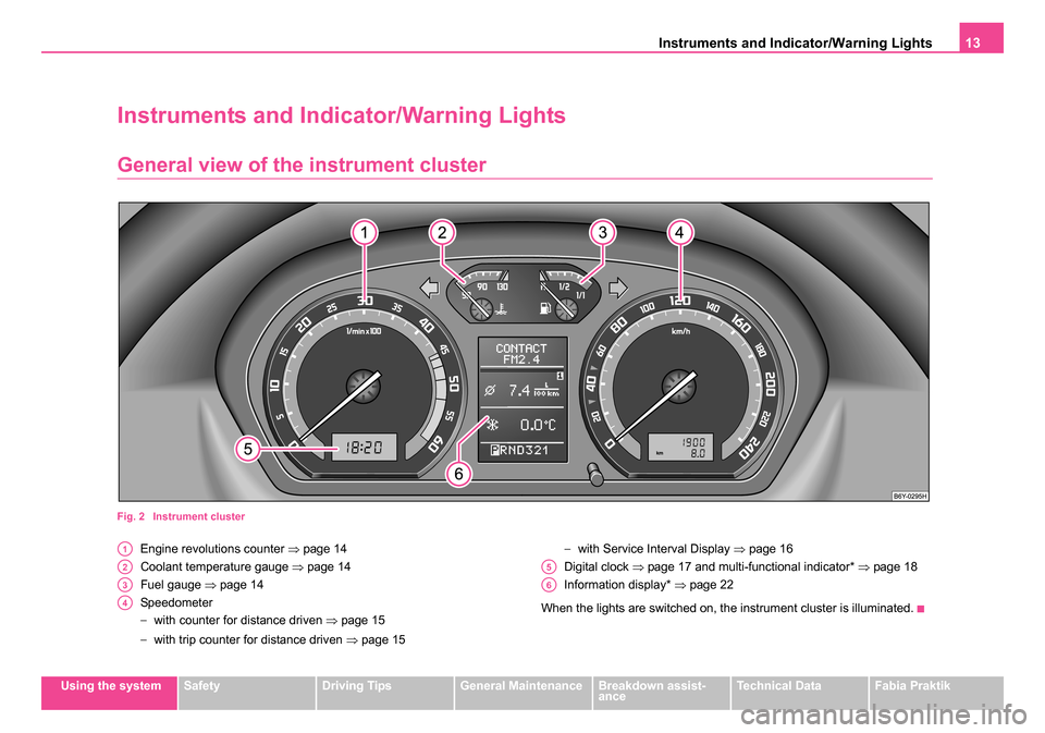
Fig. 2 Instrument cluster
Engine revolutions counter ⇒page 14
Coolant temperature gauge ⇒page 14
Fuel gauge ⇒page 14
Speedometer
− with counter for distance driven ⇒page 15
− with trip counter for distance driven ⇒page 15 −
with Service Interval Display ⇒page 16
Digital clock ⇒page 17 and multi-functional indicator* ⇒ page 18
Information display* ⇒page 22
When the lights are switched on, the instrument cluster is illuminated.A1
A2
A3
A4
A5
A6
sqc.1.book Seite 13 Mittwoch, 13. April 2005 1:09 13
Page 15 of 260
Instruments and Indicator/Warning Lights
14
Engine revolutions counter
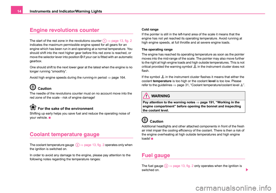
The start of the red zone in the revolutions counter ⇒page 13, fig. 2
indicates the maximum permissible engine speed for all gears for an
engine which has been run in and operating at a normal temperature. You
should shift into the next higher gear before this red zone is reached, or
move the selector lever into position D if your car is fitted with an automatic
gearbox.
One should shift to the next lower gear at the latest when the engine is no
longer running “smoothly”.
Avoid high engine speeds during the running-in period ⇒page 164.
Caution
The needle of the revolutions counter must on no account move into the
red zone of the scale - risk of engine damage!
For the sake of the environment
Shifting up early helps you save fuel and reduce the operating noise of
your vehicle.
Coolant temperature gauge
The coolant temperature gauge ⇒ page 13, fig. 2 operates only when
the ignition is switched on.
In order to avoid any damage to the engine, please pay attention to the
following notes regarding the temperature ranges: Cold range
If the pointer is still in the left-hand area of the scale it means that the
engine has not yet reached its operating temperature. Avoid running at
high engine speeds, at full throttle and at severe engine loads.
The operating range
The engine has reached its operating temperature as soon as the pointer
moves into the mid-range of the scale. The pointer may also move further
to the right at high engine loads and high outside temperatures. This is not
critical provided the warning symbol
in the instrument cluster does not
flash.
If the symbol
in the instrument cluster flashes it means that either the
coolant temperature is too high or the coolant level is too low. Please
refer to the guidelines ⇒page 31, “Coolant temperature/coolant level ”.
WARNING
Pay attention to the warning notes ⇒page 191, “Working in the
engine compartment” before opening the bonnet and inspecting
the coolant level.
Caution
Additional headlights and other attached components in front of the fresh
air inlet impair the cooling efficiency of the coolant. There is then a risk of
the engine overheating at high outside temperatures and high engine
loads!
Fuel gauge
The fuel gauge ⇒page 13, fig. 2 only operates when the ignition is
switched on.
A1
A2
A3
sqc.1.book Seite 14 Mittwoch, 13. April 2005 1:09 13
Page 17 of 260
Instruments and Indicator/Warning Lights
16
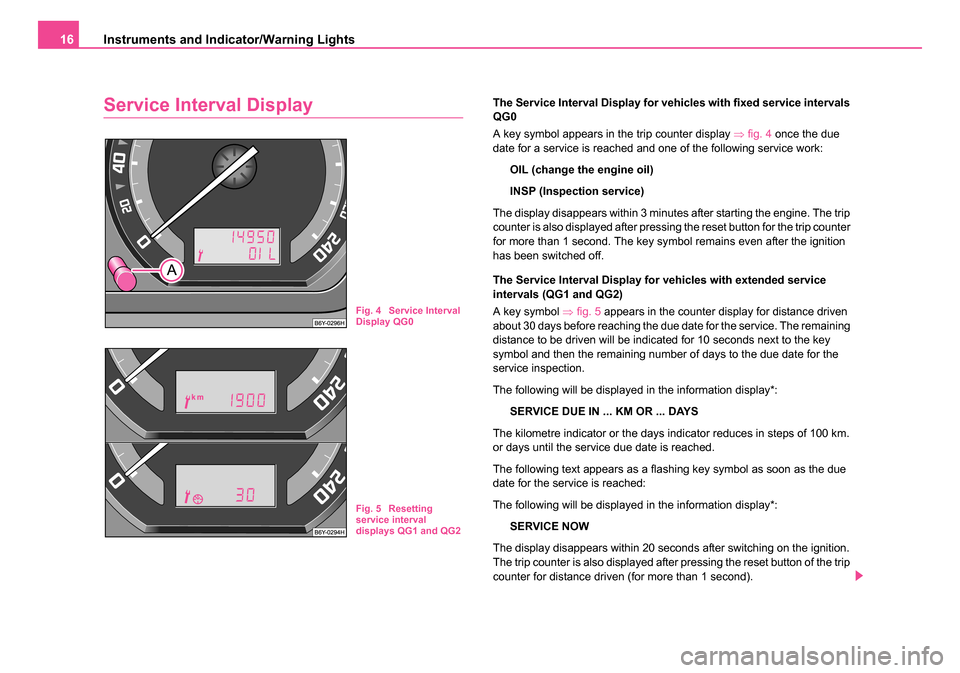
Service Interval DisplayThe Service Interval Display for vehicles with fixed service intervals
QG0
A key symbol appears in the trip counter display ⇒fig. 4 once the due
date for a service is reached and one of the following service work:
OIL (change the engine oil)
INSP (Inspection service)
The display disappears within 3 minutes after starting the engine. The trip
counter is also displayed after pressing the reset button for the trip counter
for more than 1 second. The key symbol remains even after the ignition
has been switched off.
The Service Interval Display for vehicles with extended service
intervals (QG1 and QG2)
A key symbol ⇒fig. 5 appears in the counter display for distance driven
about 30 days before reaching the due date for the service. The remaining
distance to be driven will be indicated for 10 seconds next to the key
symbol and then the remaining number of days to the due date for the
service inspection.
The following will be displayed in the information display*:
SERVICE DUE IN ... KM OR ... DAYS
The kilometre indicator or the days indicator reduces in steps of 100 km.
or days until the service due date is reached.
The following text appears as a flashing key symbol as soon as the due
date for the service is reached:
The following will be displayed in the information display*: SERVICE NOW
The display disappears within 20 seconds after switching on the ignition.
The trip counter is also displayed after pressing the reset button of the trip
counter for distance driven (for more than 1 second).
Fig. 4 Service Interval
Display QG0
Fig. 5 Resetting
service interval
displays QG1 and QG2
sqc.1.book Seite 16 Mittwoch, 13. April 2005 1:09 13
Page 19 of 260
Instruments and Indicator/Warning Lights
18
Setting minutes
– Turn the reset button to the right.
WARNING
The clock should not be adjusted while driving for safety reasons
but only when the vehicle is stationary.
Multi-functional indicator* (onboard
computer)
Introduction
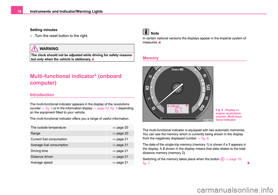
The multi-functional indicator appears in the display of the revolutions
counter ⇒fig. 6 or in the information display ⇒page 22, fig. 9 depending
on the equipment fitted to your vehicle.
The multi-functional indicator offers you a range of useful information.
Note
In certain national versions the displays appear in the Imperial system of
measures.
Memory
The multi-functional indicator is equipped with two automatic memories.
You can see the memory which is currently being shown in the display
from the negatively displayed number ⇒fig. 6 .
The data of the single-trip memory (memory 1) is shown if a 1 appears in
the display. A 2 shown in the display means that data relates to the total
distance memory (memory 2).
Switching of the memory takes place when the button ⇒page 19,
fig. 7 .The outside temperature⇒page 20
Range⇒page 20
Current fuel consumption⇒page 21
Average fuel consumption⇒page 21
Driving time⇒page 21
Distance driven⇒page 21
Average speed⇒page 21
Fig. 6 Display in
engine revolutions
counter: Multi-func-
tional indicator
AB
sqc.1.book Seite 18 Mittwoch, 13. April 2005 1:09 13
Page 21 of 260

Instruments and Indicator/Warning Lights
20
The following readouts of the selected memory will be set to zero by
button :
•average fuel consumption,
•distance driven,
•average speed,
•Driving time.
You can only operate the multi-functional indicator when the ignition is
switched on. After the ignition is switched on, the function displayed is the
one which you last selected before switching off the ignition.
The outside temperature indicator will appear with a snowflake symbol
and a warning signal sounds* when the outside temperature lies between
+5°C and -5°C. The symbol warns the driver of the possible danger of ice
on the road. After the rocker switch is pressed, the function displays
the one which you last selected before switching off the ignition.
The outside temperature
The outside temperature appears in the display when the ignition is
switched on.
The correct outside temperature will be indicated with a delay of 5
minutes. If the vehicle is stationary (or driven at a very low speed) the
temperature indicated may be slightly higher than the actual outside
temperature because of heat radiated by the engine.
The outside temperature indicator will appear with a snowflake symbol
(warning signal for ice on the road) ⇒fig. 8 and a warning signal sounds*
when the outside temperature lies between +5°C and -5°C.
WARNING
Do not only rely upon the information given on the outside temper-
ature display that there is no ice on the road. Please note that black
ice may also be present on the road surface even at temperatures
around +5°C - warning, drive with care!
Note
The outside temperature is not indicating when showing navigation data
(guidance to the destination). It must be called up over the menu (valid for
vehicles which have a navigation and information display).
Range
The estimated range in kilometres is shown on the display. It indicates the
distance you can still drive with your vehicle based on the present level of
fuel in the tank for the same style of driving. The readout is shown in steps
of 5 km.
The fuel consumption for the last 50 km is taken as a basis for calculating
the range. If you drive in a more economical manner from this moment on,
the range will be increased accordingly.
AB
AA
Fig. 8 Multi-functional
indicator: the outside
temperature
sqc.1.book Seite 20 Mittwoch, 13. April 2005 1:09 13
Page 26 of 260
Instruments and Indicator/Warning Lights25
Using the systemSafetyDriving TipsGeneral MaintenanceBreakdown assist-
anceTechnical DataFabia Praktik
The red symbols indicate
danger (priority 1) while the yellow symbols indi-
cate a warning (priortity 2). Information for the driver may also appear in
addition to the symbols ⇒page 28.
Investigate the displayed faults as soon as possible. If several operational
faults exist at the same time, the symbols will appear one after the other
and are each visible for about 2 seconds.
The error messages are faded out after 10 seconds or by actuating the
rocker switch ⇒page 23, fig. 11 and are stored under the information
CAR STATUS .
There is at least one error message to be read when the term CAR
STATUS is flashing in the main menu. The display will show STATUS 1/2
(for example) if a number of error messages are present. This display indi-
cates that the first of a total of two error messages should be displayed.
Actuate the rocker switch , to call up the individual error messages.
If a fault occurs, a warning signal will also sound in addition to the symbol
and text in the display:
•Priority 1 - three warning signals,
•Priority 2 - one warning signal.
Operational check of the automatic gearbox
When the ignition is switched on, the Auto Check Control automatically
carries out an operational check. The following text will appear first in the
display if the selector lever is the position P or N:
P LOCKED (P locked)
or N LOCKED (N locked) You must depress the brake pedal first and press the Shiftlock button at
the same time in order to move the selector lever out of these positions.
The text will disappear once you select a drive position (
R, D etc.), and the
Auto Check Control function is displayed.
If the Auto Check Control detects faults, these will be displayed about 15
seconds after starting the engine in place of the text shown above. A
warning signal sounds at the same time.
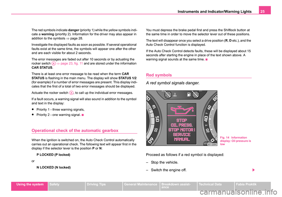
Red symbols
A red symbol signals danger.
Proceed as follows if a red symbol is displayed:
– Stop the vehicle.
– Switch the engine off.
AA
AA
Fig. 14 Information
display: Oil pressure is
low
sqc.1.book Seite 25 Mittwoch, 13. April 2005 1:09 13
Page 27 of 260
Instruments and Indicator/Warning Lights
26
– Investigate the function indicated.
– Obtain professional assistance.
Meaning of the red symbols:
Three successive warning signals will sound if a red symbol appears. The
symbol continues flashing until the fault is rectified.
If several operational faults of priority 1 exist, the symbols appear one after
the other and are each illiminated for about 2 seconds.
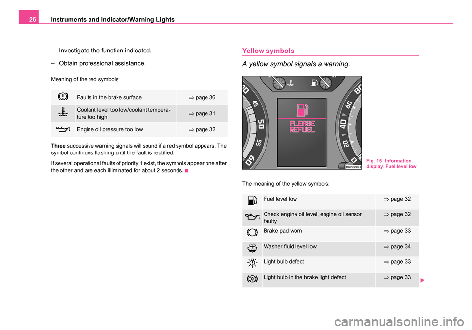
Yellow symbols
A yellow symbol signals a warning.
The meaning of the yellow symbols:
Faults in the brake surface⇒ page 36
Coolant level too low/coolant tempera-
ture too high⇒page 31
Engine oil pressure too low⇒page 32
Fuel level low⇒page 32
Check engine oil level, engine oil sensor
faulty⇒page 32
Brake pad worn⇒page 33
Washer fluid level low⇒page 34
Light bulb defect⇒page 33
Light bulb in the brake light defect⇒page 33
Fig. 15 Information
display: Fuel level low
sqc.1.book Seite 26 Mittwoch, 13. April 2005 1:09 13