navigation SKODA FABIA 2005 1.G / 6Y Owner's Manual
[x] Cancel search | Manufacturer: SKODA, Model Year: 2005, Model line: FABIA, Model: SKODA FABIA 2005 1.G / 6YPages: 260
Page 12 of 260
Cockpit11
Using the systemSafetyDriving TipsGeneral MaintenanceBreakdown assist-
anceTechnical DataFabia Praktik
Cockpit
An overview
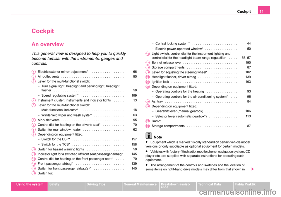
This general view is designed to help you to quickly
become familiar with the instruments, gauges and
controls.
Electric exterior mirror adjustment* . . . . . . . . . . . . . . . . . . .
Air outlet vents . . . . . . . . . . . . . . . . . . . . . . . . . . . . . . . . . . .
Lever for the multi-functional switch:
−Turn signal light, headlight and parking light, headlight
flasher . . . . . . . . . . . . . . . . . . . . . . . . . . . . . . . . . . . . . . .
− Speed regulating system* . . . . . . . . . . . . . . . . . . . . . . . .
Instrument cluster: Instruments and indicator lights . . . . . .
Lever for the multi-functional switch:
− Multi-functional indicator* . . . . . . . . . . . . . . . . . . . . . . . .
− Windshield wiper and wash system . . . . . . . . . . . . . . . . .
Air outlet vents . . . . . . . . . . . . . . . . . . . . . . . . . . . . . . . . . . .
Control dial for heating on the driver's seat* . . . . . . . . . . . .
Switch for rear window heater . . . . . . . . . . . . . . . . . . . . . . .
Depending on equipment fitted:
− Switch for the ESP* . . . . . . . . . . . . . . . . . . . . . . . . . . . . .
− Switch for the TCS* . . . . . . . . . . . . . . . . . . . . . . . . . . . . .
Switch for hazard warning lights . . . . . . . . . . . . . . . . . . . . .
Indicator light for a switched off front seat passenger airbag*
Control dial for heating on the front passenger seat* . . . . .
Front passenger airbag* . . . . . . . . . . . . . . . . . . . . . . . . . . .
Switch for front passenger airbag(s)* . . . . . . . . . . . . . . . . .
Switch for: −
Central locking system* . . . . . . . . . . . . . . . . . . . . . . . . .
− Electric power-operated window* . . . . . . . . . . . . . . . . . .
Light switch, control dial for the instrument lighting and
control dial for the headlight beam range regulatiion . . . . .
Bonnet release lever . . . . . . . . . . . . . . . . . . . . . . . . . . . . . .
Storage compartments . . . . . . . . . . . . . . . . . . . . . . . . . . . .
Lever for adjusting the steering wheel* . . . . . . . . . . . . . . .
Headlight flasher, driver airbag . . . . . . . . . . . . . . . . . . . . . .
Ignition lock . . . . . . . . . . . . . . . . . . . . . . . . . . . . . . . . . . . . .
Depending on equipment fitted:
− Operating controls for the heating . . . . . . . . . . . . . . . . .
− Operating controls for the air conditioning system* . . . .
Ashtray . . . . . . . . . . . . . . . . . . . . . . . . . . . . . . . . . . . . . . . .
Depending on equipment fitted:
− Gearshift lever (manual gearbox) . . . . . . . . . . . . . . . . . .
− Selector lever (automatic gearbox*) . . . . . . . . . . . . . . . .
Radio*
Storage compartments . . . . . . . . . . . . . . . . . . . . . . . . . . . .
Note
•Equipment which is marked * is only standard on certain vehicle model
versions or only suppliable as optional equipment for certain models.
•Vehicles with factory-fitted radio, mobile phone, navigation system, CD
player etc. are supplied with separate instructions for operating such
equipment.
•The arrangement of the controls and switches and the location of
some items on right-hand drive models may differ from that shown in
A166
A295
A3
58
109
A413
A5
18
63
A695
A770
A862
A9
157
158
A1058
A11145
A1270
A13139
A14145
A15
44
50
A1655, 57
A17190
A1887
A19102
A20139
A21103
A22
93
96
A2384
A24
106 11 3
A25
A2687
sqc.1.book Seite 11 Mittwoch, 13. April 2005 1:09 13
Page 21 of 260

Instruments and Indicator/Warning Lights
20
The following readouts of the selected memory will be set to zero by
button :
•average fuel consumption,
•distance driven,
•average speed,
•Driving time.
You can only operate the multi-functional indicator when the ignition is
switched on. After the ignition is switched on, the function displayed is the
one which you last selected before switching off the ignition.
The outside temperature indicator will appear with a snowflake symbol
and a warning signal sounds* when the outside temperature lies between
+5°C and -5°C. The symbol warns the driver of the possible danger of ice
on the road. After the rocker switch is pressed, the function displays
the one which you last selected before switching off the ignition.
The outside temperature
The outside temperature appears in the display when the ignition is
switched on.
The correct outside temperature will be indicated with a delay of 5
minutes. If the vehicle is stationary (or driven at a very low speed) the
temperature indicated may be slightly higher than the actual outside
temperature because of heat radiated by the engine.
The outside temperature indicator will appear with a snowflake symbol
(warning signal for ice on the road) ⇒fig. 8 and a warning signal sounds*
when the outside temperature lies between +5°C and -5°C.
WARNING
Do not only rely upon the information given on the outside temper-
ature display that there is no ice on the road. Please note that black
ice may also be present on the road surface even at temperatures
around +5°C - warning, drive with care!
Note
The outside temperature is not indicating when showing navigation data
(guidance to the destination). It must be called up over the menu (valid for
vehicles which have a navigation and information display).
Range
The estimated range in kilometres is shown on the display. It indicates the
distance you can still drive with your vehicle based on the present level of
fuel in the tank for the same style of driving. The readout is shown in steps
of 5 km.
The fuel consumption for the last 50 km is taken as a basis for calculating
the range. If you drive in a more economical manner from this moment on,
the range will be increased accordingly.
AB
AA
Fig. 8 Multi-functional
indicator: the outside
temperature
sqc.1.book Seite 20 Mittwoch, 13. April 2005 1:09 13
Page 23 of 260
Instruments and Indicator/Warning Lights
22
Information display*
Introduction
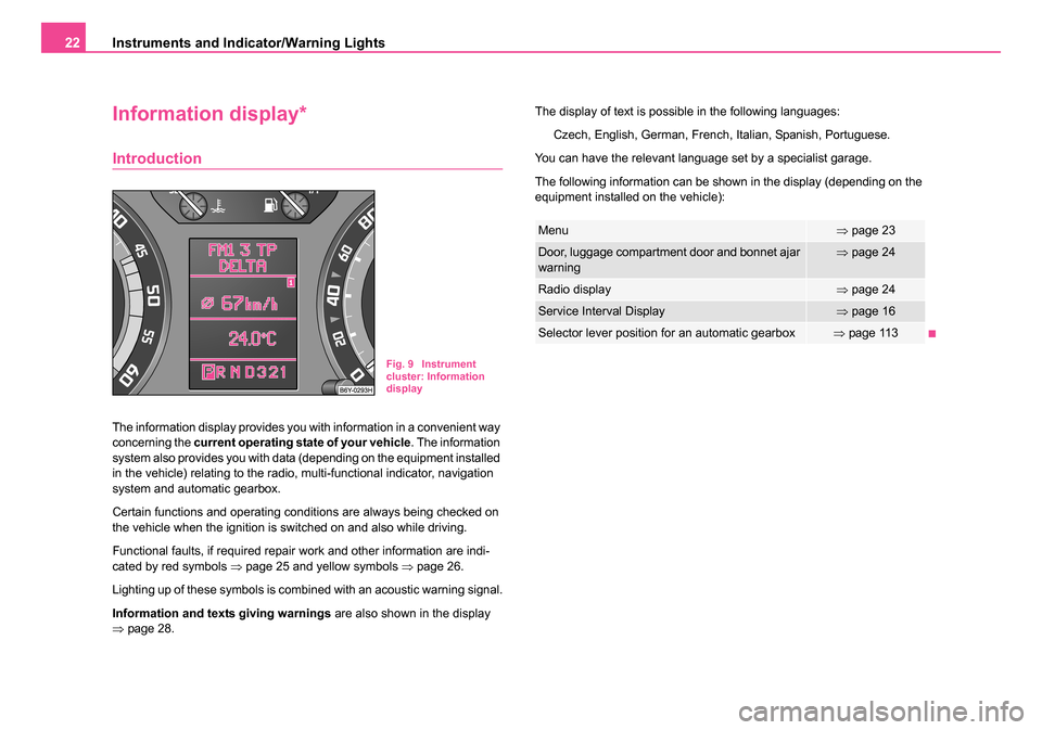
The information display provides you with information in a convenient way
concerning the current operating state of your vehicle . The information
system also provides you with data (depending on the equipment installed
in the vehicle) relating to the radio, multi-functional indicator, navigation
system and automatic gearbox.
Certain functions and operating conditions are always being checked on
the vehicle when the ignition is switched on and also while driving.
Functional faults, if required repair work and other information are indi-
cated by red symbols ⇒page 25 and yellow symbols ⇒page 26.
Lighting up of these symbols is combined with an acoustic warning signal.
Information and texts giving warnings are also shown in the display
⇒ page 28. The display of text is possible in the following languages:
Czech, English, German, French, Italian, Spanish, Portuguese.
You can have the relevant language set by a specialist garage.
The following information can be shown in the display (depending on the
equipment installed on the vehicle):
Fig. 9 Instrument
cluster: Information
display
Menu⇒ page 23
Door, luggage compartment door and bonnet ajar
warning⇒page 24
Radio display⇒page 24
Service Interval Display⇒page 16
Selector lever position for an automatic gearbox⇒page 113
sqc.1.book Seite 22 Mittwoch, 13. April 2005 1:09 13
Page 24 of 260
Instruments and Indicator/Warning Lights23
Using the systemSafetyDriving TipsGeneral MaintenanceBreakdown assist-
anceTechnical DataFabia Praktik
Menu
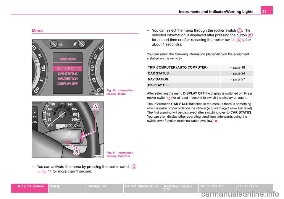
– You can activate the menu by pressing the rocker switch
⇒fig. 11 for more than 1 second. – You can select the menu through the rocker switch . The
selected information is displayed after pressing the button
for a short time or after releasing the rocker switch (after
about 4 seconds).
You can select the following information (depending on the equipment
installed on the vehicle):
After selecting the menu DISPLAY OFF the display is switched off. Press
rocker switch for at least 1 second to switch the display on again.
The Information CAR STATUSflashes in the menu if there is something
which is not in proper order on the vehicle (e.g. warning of a low fuel level).
The first warning will be displayed after switching over to CAR STATUS.
You can then display other operating conditions afterwards using the
switch-over function (such as water level low).
Fig. 10 Information
display: Menu
Fig. 11 Information
display: Controls
AA
TRIP COMPUTER (AUTO COMPUTER)⇒ page 18
CAR STATUS⇒page 24
NAVIGATION⇒page 27
DISPLAY OFF
AA
AB
AA
AA
sqc.1.book Seite 23 Mittwoch, 13. April 2005 1:09 13
Page 28 of 260
Instruments and Indicator/Warning Lights27
Using the systemSafetyDriving TipsGeneral MaintenanceBreakdown assist-
anceTechnical DataFabia Praktik
One
warning signal will sound if a yellow symbol appears.
If several operational faults of priority 2 exist, the symbols appear one after
the other and are each illiminated for about 2 seconds.
Check the relevant function as soon as possible.
Navigation system*
The controls for the navigation system, radio, CD player are located in the
centre console on both sides of the monitor screen. Navigation data is
also shown in the information display of the instrument cluster.
Information and warning texts are displayed preferentially when the navi-
gation system is switched on.
Operation of the navigation system is described in separate operating
instructions to be found in the on-board literature.
sqc.1.book Seite 27 Mittwoch, 13. April 2005 1:09 13
Page 120 of 260

Communication119
Using the systemSafetyDriving TipsGeneral MaintenanceBreakdown assist-
anceTechnical DataFabia Praktik
The CD changer*
Take out and insert CD magazine
The CD changer for the radio and navigation system is located
under the front passenger seat.
Take magazine out of the changer
– Open safety stop ⇒page 119, fig. 99 fully.
– Press button . The magazine is automatically ejected.
– Take out the magazine.
Insert magazine into the changer
– Insert the magazine with the arrow of the illustration upwards up to the stop ⇒ fig. 100. The tip of the arrow on the magazine
must point at the same time to the magazine box. – Slide safety stop closed.
After inserting the magazine, it is analysed how many CDs are in the
magazine.
If there is no magazine in the changer,
NO CD MAGAZINE is displayed in
the CD-mode on the display of the radio.
You can also take out the magazine when the radio is switched off.
Caution
Always close the safety cover after inserting the magazine. The safety
cover protects the CD-changer from dirt and dust particles penetrating into
the CD-changer, in order to avoid operational faults.
Note
•Described in this Owner's Manual are only the steps required for the
operation of the CD-changer.
•You will find further information for this setting menu in the Radio
Owner's Manual.
•Only Use CD-magazines from Škoda Original Accessories.
Fig. 99 The CD
changer
A1
A3A2
sqc.1.book Seite 119 Mittwoch, 13. April 2005 1:09 13
Page 235 of 260
Fuses and light bulbs
234
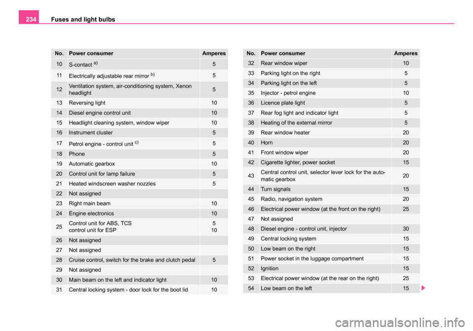
10S-contact a)5
11Electrically adjustable rear mirror b)5
12Ventilation system, air-conditioning system, Xenon
headlight5
13Reversing light10
14Diesel engine control unit10
15Headlight cleaning system, window wiper10
16Instrument cluster5
17Petrol engine - control unit c)5
18Phone5
19Automatic gearbox10
20Control unit for lamp failure5
21Heated windscreen washer nozzles5
22Not assigned
23Right main beam10
24Engine electronics10
25Control unit for ABS, TCS
control unit for ESP5
10
26Not assigned
27Not assigned
28Cruise control, switch for the brake and clutch pedal5
29Not assigned
30Main beam on the left and indicator light10
31Central locking system - door lock for the boot lid10
No.Power consumerAmperes
32Rear window wiper10
33Parking light on the right5
34Parking light on the left5
35Injector - petrol engine10
36Licence plate light5
37Rear fog light and indicator light5
38Heating of the external mirror5
39Rear window heater20
40Horn20
41Front window wiper20
42Cigarette lighter, power socket15
43Central control unit, selector lever lock for the auto-
matic gearbox20
44Turn signals15
45Radio, navigation system20
46Electrical power window (at the front on the right)25
47Not assigned
48Diesel engine - control unit, injector30
49Central locking system15
50Low beam on the right15
51Power socket in the luggage compartment15
52Ignition15
53Electrical power window (at the rear on the right)25
54Low beam on the left15
No.Power consumerAmperes
sqc.1.book Seite 234 Mittwoch, 13. April 2005 1:09 13
Page 255 of 260
Index
254
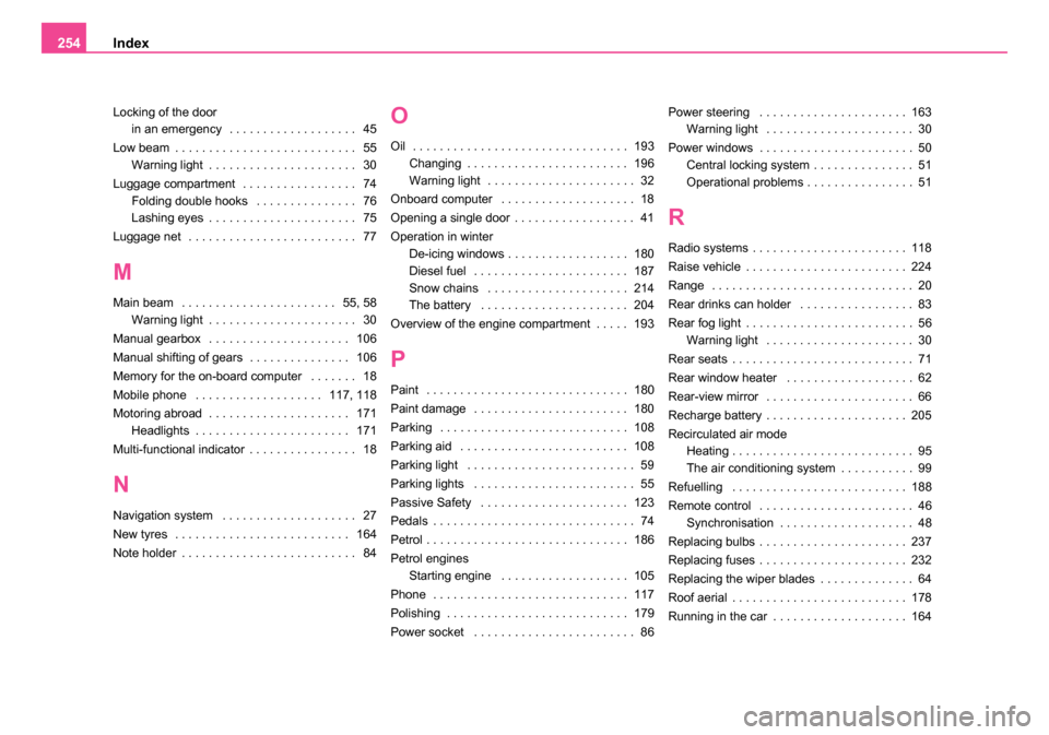
Locking of the door
in an emergency . . . . . . . . . . . . . . . . . . . 45
Low beam . . . . . . . . . . . . . . . . . . . . . . . . . . . 55 Warning light . . . . . . . . . . . . . . . . . . . . . . 30
Luggage compartment . . . . . . . . . . . . . . . . . 74 Folding double hooks . . . . . . . . . . . . . . . 76
Lashing eyes . . . . . . . . . . . . . . . . . . . . . . 75
Luggage net . . . . . . . . . . . . . . . . . . . . . . . . . 77
M
Main beam . . . . . . . . . . . . . . . . . . . . . . . 55, 58 Warning light . . . . . . . . . . . . . . . . . . . . . . 30
Manual gearbox . . . . . . . . . . . . . . . . . . . . . 106
Manual shifting of gears . . . . . . . . . . . . . . . 106
Memory for the on-board computer . . . . . . . 18
Mobile phone . . . . . . . . . . . . . . . . . . . 117, 118
Motoring abroad . . . . . . . . . . . . . . . . . . . . . 171 Headlights . . . . . . . . . . . . . . . . . . . . . . . 171
Multi-functional indicator . . . . . . . . . . . . . . . . 18
N
Navigation system . . . . . . . . . . . . . . . . . . . . 27
New tyres . . . . . . . . . . . . . . . . . . . . . . . . . . 164
Note holder . . . . . . . . . . . . . . . . . . . . . . . . . . 84
O
Oil . . . . . . . . . . . . . . . . . . . . . . . . . . . . . . . . 193 Changing . . . . . . . . . . . . . . . . . . . . . . . . 196
Warning light . . . . . . . . . . . . . . . . . . . . . . 32
Onboard computer . . . . . . . . . . . . . . . . . . . . 18
Opening a single door . . . . . . . . . . . . . . . . . . 41
Operation in winter De-icing windows . . . . . . . . . . . . . . . . . . 180
Diesel fuel . . . . . . . . . . . . . . . . . . . . . . . 187
Snow chains . . . . . . . . . . . . . . . . . . . . . 214
The battery . . . . . . . . . . . . . . . . . . . . . . 204
Overview of the engine compartment . . . . . 193
P
Paint . . . . . . . . . . . . . . . . . . . . . . . . . . . . . . 180
Paint damage . . . . . . . . . . . . . . . . . . . . . . . 180
Parking . . . . . . . . . . . . . . . . . . . . . . . . . . . . 108
Parking aid . . . . . . . . . . . . . . . . . . . . . . . . . 108
Parking light . . . . . . . . . . . . . . . . . . . . . . . . . 59
Parking lights . . . . . . . . . . . . . . . . . . . . . . . . 55
Passive Safety . . . . . . . . . . . . . . . . . . . . . . 123
Pedals . . . . . . . . . . . . . . . . . . . . . . . . . . . . . . 74
Petrol . . . . . . . . . . . . . . . . . . . . . . . . . . . . . . 186
Petrol engines Starting engine . . . . . . . . . . . . . . . . . . . 105
Phone . . . . . . . . . . . . . . . . . . . . . . . . . . . . . 117
Polishing . . . . . . . . . . . . . . . . . . . . . . . . . . . 179
Power socket . . . . . . . . . . . . . . . . . . . . . . . . 86 Power steering . . . . . . . . . . . . . . . . . . . . . . 163
Warning light . . . . . . . . . . . . . . . . . . . . . . 30
Power windows . . . . . . . . . . . . . . . . . . . . . . . 50 Central locking system . . . . . . . . . . . . . . . 51
Operational problems . . . . . . . . . . . . . . . . 51
R
Radio systems . . . . . . . . . . . . . . . . . . . . . . . 118
Raise vehicle . . . . . . . . . . . . . . . . . . . . . . . . 224
Range . . . . . . . . . . . . . . . . . . . . . . . . . . . . . . 20
Rear drinks can holder . . . . . . . . . . . . . . . . . 83
Rear fog light . . . . . . . . . . . . . . . . . . . . . . . . . 56Warning light . . . . . . . . . . . . . . . . . . . . . . 30
Rear seats . . . . . . . . . . . . . . . . . . . . . . . . . . . 71
Rear window heater . . . . . . . . . . . . . . . . . . . 62
Rear-view mirror . . . . . . . . . . . . . . . . . . . . . . 66
Recharge battery . . . . . . . . . . . . . . . . . . . . . 205
Recirculated air mode Heating . . . . . . . . . . . . . . . . . . . . . . . . . . . 95
The air conditioning system . . . . . . . . . . . 99
Refuelling . . . . . . . . . . . . . . . . . . . . . . . . . . 188
Remote control . . . . . . . . . . . . . . . . . . . . . . . 46 Synchronisation . . . . . . . . . . . . . . . . . . . . 48
Replacing bulbs . . . . . . . . . . . . . . . . . . . . . . 237
Replacing fuses . . . . . . . . . . . . . . . . . . . . . . 232
Replacing the wiper blades . . . . . . . . . . . . . . 64
Roof aerial . . . . . . . . . . . . . . . . . . . . . . . . . . 178
Running in the car . . . . . . . . . . . . . . . . . . . . 164
sqc.1.book Seite 254 Mittwoch, 13. April 2005 1:09 13