service indicator SKODA FABIA 2005 1.G / 6Y Owner's Manual
[x] Cancel search | Manufacturer: SKODA, Model Year: 2005, Model line: FABIA, Model: SKODA FABIA 2005 1.G / 6YPages: 260
Page 6 of 260
Contents5
Contents
Layout of this Owner's Manual
(explanations)
. . . . . . . . . . . . . . . . . . .
Using the system . . . . . . . . . . . . . . .
Cockpit . . . . . . . . . . . . . . . . . . . . . . . . . . . . . . .
An overview . . . . . . . . . . . . . . . . . . . . . . . . . .
Instruments and Indicator/Warning LightsGeneral view of the instrument cluster . . . . . .
Engine revolutions counter . . . . . . . . . . . . . . .
Coolant temperature gauge . . . . . . . . . . . . . .
Fuel gauge . . . . . . . . . . . . . . . . . . . . . . . . . . .
Speedometer with counter for distance driven
Service Interval Display . . . . . . . . . . . . . . . . .
Digital clock . . . . . . . . . . . . . . . . . . . . . . . . . .
Multi-functional indicator* (onboard computer)
Information display* . . . . . . . . . . . . . . . . . . . .
Auto Check Control . . . . . . . . . . . . . . . . . . . .
Warning lights . . . . . . . . . . . . . . . . . . . . . . . . .
Unlocking and locking . . . . . . . . . . . . . . . . . .
Keys . . . . . . . . . . . . . . . . . . . . . . . . . . . . . . . .
Locking . . . . . . . . . . . . . . . . . . . . . . . . . . . . . .
Child safety locks . . . . . . . . . . . . . . . . . . . . . .
Central locking system* . . . . . . . . . . . . . . . . .
Remote control* . . . . . . . . . . . . . . . . . . . . . . .
Anti-theft alarm system* . . . . . . . . . . . . . . . . .
Power windows* . . . . . . . . . . . . . . . . . . . . . . .
Electric sliding/tilting roof* . . . . . . . . . . . . . . .
Lights and Visibility. . . . . . . . . . . . . . . . . . . . .
Lights . . . . . . . . . . . . . . . . . . . . . . . . . . . . . . .
Interior lighting . . . . . . . . . . . . . . . . . . . . . . . .
Visibility . . . . . . . . . . . . . . . . . . . . . . . . . . . . . Windshield wiper and wash system . . . . . . . .
Rear-view mirror . . . . . . . . . . . . . . . . . . . . . .
Seats and Stowage . . . . . . . . . . . . . . . . . . . .
Front seats . . . . . . . . . . . . . . . . . . . . . . . . . . .
Head restraints . . . . . . . . . . . . . . . . . . . . . . . .
Middle rear head restraint* . . . . . . . . . . . . . . .
Heating the front seats* . . . . . . . . . . . . . . . . .
Rear seats . . . . . . . . . . . . . . . . . . . . . . . . . . .
Pedals . . . . . . . . . . . . . . . . . . . . . . . . . . . . . .
Luggage compartment . . . . . . . . . . . . . . . . . .
Net partition (Estate)* . . . . . . . . . . . . . . . . . . .
The roof luggage rack system* . . . . . . . . . . .
Drinks can holder* . . . . . . . . . . . . . . . . . . . . .
Rear drinks can holder * . . . . . . . . . . . . . . . .
Note holder . . . . . . . . . . . . . . . . . . . . . . . . . .
Ashtray at the front* . . . . . . . . . . . . . . . . . . . .
Ashtray at the rear* . . . . . . . . . . . . . . . . . . . .
Cigarette lighter* and power socket* . . . . . . .
Storage compartments . . . . . . . . . . . . . . . . . .
Heating and air conditioning system . . . . .
Heating . . . . . . . . . . . . . . . . . . . . . . . . . . . . . .
The air conditioning system* . . . . . . . . . . . . .
Starting-off and Driving. . . . . . . . . . . . . . . . .
Setting steering wheel position* . . . . . . . . . . .
Ignition lock . . . . . . . . . . . . . . . . . . . . . . . . . .
Starting engine . . . . . . . . . . . . . . . . . . . . . . . .
Switching the engine off . . . . . . . . . . . . . . . . .
Shifting (manual gearbox) . . . . . . . . . . . . . . .
Handbrake . . . . . . . . . . . . . . . . . . . . . . . . . . .
Parking aid* . . . . . . . . . . . . . . . . . . . . . . . . . .
Cruise control system (CCS)* . . . . . . . . . . . .
Automatic gearbox*. . . . . . . . . . . . . . . . . . . .
4-speed automatic gearbox . . . . . . . . . . . . . .
Communication . . . . . . . . . . . . . . . . . . . . . . .
Universal telephone connection* . . . . . . . . . .
Mobile phones and two-way radio systems . .
The CD changer* . . . . . . . . . . . . . . . . . . . . . .
Safety. . . . . . . . . . . . . . . . . . . . . . . . . . . . . .
Passive Safety . . . . . . . . . . . . . . . . . . . . . . . .
Basic information . . . . . . . . . . . . . . . . . . . . . .
Correct seated position . . . . . . . . . . . . . . . . .
Seat belts. . . . . . . . . . . . . . . . . . . . . . . . . . . . .
Why seat belts? . . . . . . . . . . . . . . . . . . . . . . .
The physical principle of a frontal collision . .
Important safety information regarding the use
of seat belts . . . . . . . . . . . . . . . . . . . . . . . . . .
How are seat belts correctly fastened? . . . . .
Belt tensioners . . . . . . . . . . . . . . . . . . . . . . . .
Airbag system. . . . . . . . . . . . . . . . . . . . . . . . .
Description of the airbag system . . . . . . . . . .
Front airbags . . . . . . . . . . . . . . . . . . . . . . . . .
Side airbags* . . . . . . . . . . . . . . . . . . . . . . . . .
Deactivating an airbag . . . . . . . . . . . . . . . . . .
Transporting children safely . . . . . . . . . . . .
What you should know about transporting
children! . . . . . . . . . . . . . . . . . . . . . . . . . . . . .
Child seat . . . . . . . . . . . . . . . . . . . . . . . . . . . .
Attaching a child seat using the “ISOFIX”*
system . . . . . . . . . . . . . . . . . . . . . . . . . . . . . .
8
9
11
11
13
13
14
14
14
15
16
17
18
22
24
28
38
38
40
41
41
46
49
50
52
55
55
60
62 63
66
67
67
69
70
70
71
74
74
79
81
83
83
84
84
85
85
87
93
93
96
102
102
103
104
105
106
107
108
109 11 2
11 2 11 7
11 7
11 8
11 9
123
123
123
125
129
129
130
131
132
135
137
137
139
141
144
147
147
151
155
sqc.1.book Seite 5 Mittwoch, 13. April 2005 1:09 13
Page 14 of 260
Instruments and Indicator/Warning Lights13
Using the systemSafetyDriving TipsGeneral MaintenanceBreakdown assist-
anceTechnical DataFabia Praktik
Instruments and Indicator/Warning Lights
General view of the instrument cluster
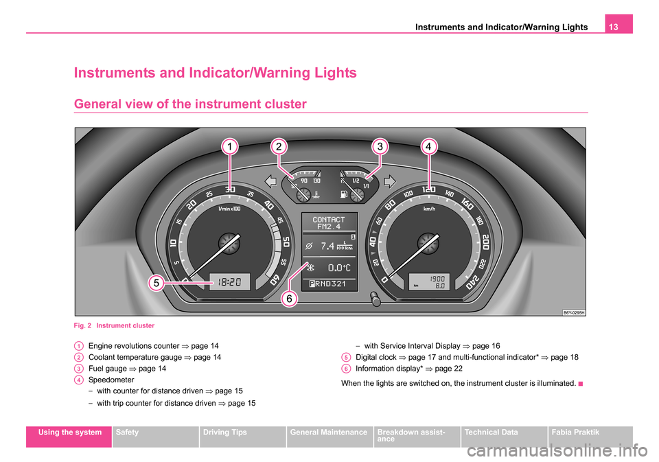
Fig. 2 Instrument cluster
Engine revolutions counter ⇒page 14
Coolant temperature gauge ⇒page 14
Fuel gauge ⇒page 14
Speedometer
− with counter for distance driven ⇒page 15
− with trip counter for distance driven ⇒page 15 −
with Service Interval Display ⇒page 16
Digital clock ⇒page 17 and multi-functional indicator* ⇒ page 18
Information display* ⇒page 22
When the lights are switched on, the instrument cluster is illuminated.A1
A2
A3
A4
A5
A6
sqc.1.book Seite 13 Mittwoch, 13. April 2005 1:09 13
Page 17 of 260
Instruments and Indicator/Warning Lights
16
Service Interval DisplayThe Service Interval Display for vehicles with fixed service intervals
QG0
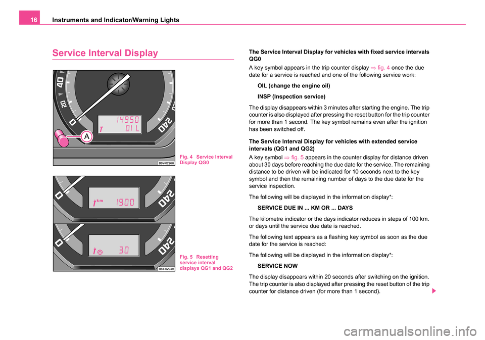
A key symbol appears in the trip counter display ⇒fig. 4 once the due
date for a service is reached and one of the following service work:
OIL (change the engine oil)
INSP (Inspection service)
The display disappears within 3 minutes after starting the engine. The trip
counter is also displayed after pressing the reset button for the trip counter
for more than 1 second. The key symbol remains even after the ignition
has been switched off.
The Service Interval Display for vehicles with extended service
intervals (QG1 and QG2)
A key symbol ⇒fig. 5 appears in the counter display for distance driven
about 30 days before reaching the due date for the service. The remaining
distance to be driven will be indicated for 10 seconds next to the key
symbol and then the remaining number of days to the due date for the
service inspection.
The following will be displayed in the information display*:
SERVICE DUE IN ... KM OR ... DAYS
The kilometre indicator or the days indicator reduces in steps of 100 km.
or days until the service due date is reached.
The following text appears as a flashing key symbol as soon as the due
date for the service is reached:
The following will be displayed in the information display*: SERVICE NOW
The display disappears within 20 seconds after switching on the ignition.
The trip counter is also displayed after pressing the reset button of the trip
counter for distance driven (for more than 1 second).
Fig. 4 Service Interval
Display QG0
Fig. 5 Resetting
service interval
displays QG1 and QG2
sqc.1.book Seite 16 Mittwoch, 13. April 2005 1:09 13
Page 18 of 260
Instruments and Indicator/Warning Lights17
Using the systemSafetyDriving TipsGeneral MaintenanceBreakdown assist-
anceTechnical DataFabia Praktik
Resetting Service Interval Display
We recommend having this resetting performed by a specialist garage.
Specialist garage:
•resets the memory of the display after the appropriate inspection,
•makes an entry in the Service schedule,
•affix the sticker with the entry of the following service interval to the
side of the dash panel on the driver's side.
It is also possible for you to reset the Service Interval Display with the
reset button ⇒page 16, fig. 4 as follows:
Models with fixed service intervals (QG0)
Press the reset button ⇒page 16, fig. 4 with the ignition switched off
and and hold it down.
If the ignition is switched on, one of the service intervals appears in the
display. Holding the reset button down for 10 seconds will cause the
counter to be reset (the display shows “- - -” and then the trip counter
readout).
The readout OIL will appear in the display after resetting the indicator
INSP and releasing the reset button when both service intervals (INSP
and OIL) were reached together.
Repress the reset button and hold it down for 10 seconds to also reset
this interval.
Vehicles with extended service intervals (QG1 and QG2)
Press the reset button ⇒page 16, fig. 4 with the ignition switched off
and and hold it down.
Switch the ignition on, release the reset button and and turn the reset
button to the right. All counters will be reset to 0.
Caution
We recommend that you do not reset the Service Interval Display yourself
otherwise this can result in the service interval display being incorrectly
set, which may also result in problems with operation of your vehicle.
Note
•Never reset the display between service intervals otherwise this may
result in incorrect readouts.
•information is retained in the Service Interval Display also after the
battery of the vehicle is disconnected.
•it is necessary to re-code the Service Interval Display if a new instru-
ment cluster is installed during repair work. This work is carried out by a
specialist garage.
•After resetting the display with flexible service intervals (QG1) using
the reset button , the data displayed are the same as for a car with fixed
service intervals (QG2). We therefore recommend having the Service
Interval Display reset only by a Škoda dealer who is familiar with the
procedure for resetting the display with a vehicle system tester.
•Please refer to the brochure Service schedule for extensive informa-
tion about the service intervals.
Digital clock
A reset button is installed on the left below beside the speedom-
eter for adjusting the clock ⇒page 13, fig. 2 .
Set hours
– Turn the reset button to the left.
AA
AA
AA
AA
AA
AA
AA
AA
sqc.1.book Seite 17 Mittwoch, 13. April 2005 1:09 13
Page 23 of 260
Instruments and Indicator/Warning Lights
22
Information display*
Introduction
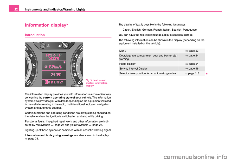
The information display provides you with information in a convenient way
concerning the current operating state of your vehicle . The information
system also provides you with data (depending on the equipment installed
in the vehicle) relating to the radio, multi-functional indicator, navigation
system and automatic gearbox.
Certain functions and operating conditions are always being checked on
the vehicle when the ignition is switched on and also while driving.
Functional faults, if required repair work and other information are indi-
cated by red symbols ⇒page 25 and yellow symbols ⇒page 26.
Lighting up of these symbols is combined with an acoustic warning signal.
Information and texts giving warnings are also shown in the display
⇒ page 28. The display of text is possible in the following languages:
Czech, English, German, French, Italian, Spanish, Portuguese.
You can have the relevant language set by a specialist garage.
The following information can be shown in the display (depending on the
equipment installed on the vehicle):
Fig. 9 Instrument
cluster: Information
display
Menu⇒ page 23
Door, luggage compartment door and bonnet ajar
warning⇒page 24
Radio display⇒page 24
Service Interval Display⇒page 16
Selector lever position for an automatic gearbox⇒page 113
sqc.1.book Seite 22 Mittwoch, 13. April 2005 1:09 13
Page 25 of 260
Instruments and Indicator/Warning Lights
24
Door, luggage compartment door and bonnet ajar
warning
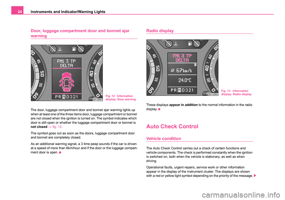
The door, luggage compartment door and bonnet ajar warning lights up
when at least one of the three items door, luggage compartment or bonnet
are not closed when the ignition is turned on. The symbol indicates which
door is still open or whether the luggage compartment door or bonnet is
not closed ⇒ fig. 12 .
The symbol goes out as soon as the doors, luggage compartment door
and bonnet are completely closed.
As an additional warning signal, a 3 time peep sounds if the car is driven
at a speed of more than 6km/hour and if the door or the luggage compart-
ment door is open.
Radio display
These displays appear in addition to the normal information in the radio
display.
Auto Check Control
Vehicle condition
The Auto Check Control carries out a check of certain functions and
vehicle components. The check is performed constantly when the ignition
is switched on, both when the vehicle is stationary, as well as when
driving.
Operational faults, urgent repairs, service work or other information
appear in the display of the instrument cluster. The displays are shown
with a red or yellow light symbol depending on the priority of the message.
Fig. 12 Information
display: Door warning
Fig. 13 Information
display: Radio display
sqc.1.book Seite 24 Mittwoch, 13. April 2005 1:09 13
Page 33 of 260
Instruments and Indicator/Warning Lights
32
3 peeps sound as an additional warning signal.
In this case stop and switch the engine off and check the coolant level;
top up the coolant as necessary.
Do not continue your journey if for some reason it is not possible under
the conditions prevailing to top up with coolant. Keep the engine
switched off and obtain professional assistance from a specialist garage,
otherwise it could lead to severe engine damage.
If the coolant is within the specified range, the increased temperature may
be caused by an operating problem at the coolant fan. Check the fuse for
the coolant fan, replace it if necessary ⇒page 236, “Fuse assignment at
battery - version 1”.
Do not continue driving if the warning light does not go off although the
fluid is at the correct level and also the fuse of the fan is in proper order.
Contact a specialist garage to obtain assistance.
Please also refer to the additional instructions ⇒page 196, “Cooling
system”.
The following text will be displayed in the information display*:
STOP CHECK COOLANT SERVICE MANUAL (STOP! CHECK
COOLANT LEVEL OWNER'S MANUAL)
WARNING
•If you must stop for technical reasons, then park the vehicle at
a safe distance from the traffic and switch off the engine and switch
on the hazard warning light system ⇒page 58.
•Take care when opening the coolant expansion bottle. If the
engine is hot, the cooling system is pressurized - risk of scalding.
It is best to allow the engine to cool down before removing the cap.
•Do not touch the coolant fan! The coolant fan may switch on
automatically even if the ignition is off.
Electronic immobiliser
Data is compared between the ignition key and the control unit when
switching on the ignition. The indicator light will light up for a few
s
econds when ignition key authorisation is confirmed.
The warning light will start flashing continuously if a non-authorised igni-
tion key (for example the wrong ignition key) has been used. The engine
cannot be started ⇒page 40.
It is only possible to start the engine of the vehicle with a Genuine Škoda
key with the matching code.
Fuel reserve
The warning light comes on, if the fuel level is still about 7 litres.
A peep sounds as an additional warning signal.
The following text will be displayed in the information display*:
PLEASE REFUEL
Engine oil
The warning light lights up red (low oil pressure)
The warning light comes on for a few seconds 2) when the ignition is
switched on.
2)The warning light on vehicles fitted with information display does not come on
after switching the ignition on, but only if a fault exists or the engine oil level is too
low.
sqc.1.book Seite 32 Mittwoch, 13. April 2005 1:09 13
Page 34 of 260
Instruments and Indicator/Warning Lights33
Using the systemSafetyDriving TipsGeneral MaintenanceBreakdown assist-
anceTechnical DataFabia Praktik
Stop the vehicle and switch the engine off
if the warning light does not
go off after the engine has started or flashes while driving. Check the oil
level and top up with oil as necessary ⇒ page 194.
3 peeps sound as an additional warning signal.
Do not continue your journey if for some reason it is not possible under
the conditions prevailing to top up with oil. Keep the engine switched off
and obtain professional assistance from a specialist garage, otherwise it
could lead to severe engine damage.
Do not drive any further if the warning light flashes even if the oil is at
the correct level. Do not run the engine not at idling speed either. Contact
the nearest specialist garage to obtain professional assistance.
The following text will be displayed in the information display*:
STOP! OIL PRESS. STOP MOTOR! SERVICE MANUAL (STOP! OIL
PRESSURE STOP ENGINE! OWNER'S MANUAL)
The warning light
lights up yellow* (oil quantity too low)
If the warning light lights up yellow, the quantity of oil in the engine is prob-
ably too low. Check as soon as possible the oil level or top up ⇒page 194
with engine oil.
A peep sounds as an additional warning signal.
The following text will be displayed in the information display*:
CHECK OIL LEVEL
The warning light will go out if the bonnet is left open for more than 30
seconds. If no engine oil has been replenished, the warning light will come
on again after driving about 100 km.
The warning light
flashes yellow* (engine oil level sensor faulty)
A fault on the engine oil level sensor is indicated additionally by an audible
signal and the warning light coming on several times after the ignition has
been switched on. In this case have the engine inspected without delay by a specialist
garage.
The following text will be displayed in the information display*:
OIL SENSOR WORKSHOP! (OIL SENSOR WORKSHOP)
WARNING
•If you must stop for technical reasons, then park the vehicle at
a safe distance from the traffic and switch off the engine and switch
on the hazard warning light system ⇒page 58.
•The red oil pressure light is not an oil le vel indicator! One
should therefore check the oil level at regular intervals, preferably
after every refueling stop.
Thickness of the brake pads*
If the warning light comes on, contact a specialist garage immediately
and have the brake pads on all of the wheels inspected.
A peep sounds as an additional warning signal.
The following text will be displayed in the information display*: CHECK BRAKE PADS
Light bulbs*
The warning light comes on if a light bulb is damaged:
•brakes applied (brake light),
•in lighting (low beam and/or rear light).
sqc.1.book Seite 33 Mittwoch, 13. April 2005 1:09 13
Page 197 of 260
Inspecting and Replenishing
196
For the sake of the environment
The oil level must on no account be above the range ⇒page 194. Oil
will otherwise be drawn in through the crankcase ventilation and may pass
through the exhaust system to atmosphere. The oil may combust in the
catalytic converter and damage it.
Changing engine oil
The engine oil must be changed at the intervals stated in the Service
schedule or according to the service interval indicator ⇒page 16.
WARNING
•Only carry out the engine oil change, if you have the required
professional knowledge!
•Read and observe the warning notes ⇒page 191, “Working in
the engine compartment” before working in the engine compart-
ment.
•Let the engine cool down - risk of burning from hot oil.
•Wear an eye protection - risk of caustic burns due to oil
splashes.
•Oil is toxic! Store old oil in a safe place out of the reach of chil-
dren and unauthorized persons until you dispose of it properly.
Caution
You must not pour any additives into the engine oil - risk of engine
damage! Damage, which results from such product, are excluded from the
warranty.
For the sake of the environment
•You must on no account pour oil into the ground or into the sewage
system.
•In view of the problems involved in properly disposing of old oil, the
material, equipment and the knowledge required for such work, we recom-
mend that you have the oil and oil filter change carried out by your Škoda
dealer.
Note
After your skin has come in contact with the oil, you must thoroughly wash
your skin.
Cooling system
Coolant
The job of the coolant is to cool the engine.
The cooling system does not require any maintenance under normal oper-
ating conditions. The coolant consists of water with a concentration of
coolant additive of 40 %. This mixture not only provides antifreeze protec-
tion down to -25°C but also protects the cooling and heating system from
corrosion. It also prevents the formation of scale and significantly
increases the boiling point of the coolant.
You must therefore not reduce the concentration of antifreeze agent in the
coolant by adding water, also not during the summer months or in coun-
tries with a warm climate. The concentration of coolant additive in the
coolant must be at least 40%.
Aa
sqc.1.book Seite 196 Mittwoch, 13. April 2005 1:09 13
Page 205 of 260

Inspecting and Replenishing
204
Battery with a charge level indicator, the so-called
magic eye*
There is a so-called magic eye ⇒fig. 148 located on the top of the battery.
The “magic eye” changes its colour in line with the charge state of and
electrolyte level in the battery.
Air bubbles can influence the colour of the “magic eye”. For this reason
carefully knock on the “magic eye” before carrying out the check.
•Green colour - the battery is adequately charged.
•Dark colour - the battery has to be charged
•Colourless or yellow colour - we recommend you have the battery
checked by a Škoda dealer.
Batteries, which are more than 5 years old, must be replaced. We recom-
mend you have the electrolyte level inspected and adjusted to the correct
level or the battery replaced if necessary by a Škoda dealer.
Caution
If the vehicle has not been driven for more than 3 to 4 weeks, the battery
will discharge because certain electrical components consume electricity
(e.g. control units) also in idle state. You can prevent the discharging of
the battery by disconnecting the negative terminal or charging the battery
constantly with a very low charging current. Please also refer to the notes
when working on the battery ⇒page 201, “Working on the battery”.
Inspecting the electrolyte level
The battery is practically maintenance-free under normal operating
conditions. We do, however, recommend that you have the electrolyte
level inspected from time to time by a Škoda dealer when outside temper-
atures are high or when driving on long trips. You should also check the
electrolyte level ⇒page 205 each time the battery is charged.
The battery acid level will also be checked as part of the Inspection
Service.
Operation in winter
The battery has to provide greater amounts of electricity during the winter.
It also has only part of the initial power output at low temperatures that it
has at normal temperatures.
A discharged battery may already freeze at temperatures just below
0°C.
We therefore recommend that you have the battery checked by a Škoda
dealer before the start of the winter, and recharged if necessary.
Fig. 148 Battery with a
charge level indicator
sqc.1.book Seite 204 Mittwoch, 13. April 2005 1:09 13