technical data SKODA FABIA 2006 2.G / 5J Owner's Manual
[x] Cancel search | Manufacturer: SKODA, Model Year: 2006, Model line: FABIA, Model: SKODA FABIA 2006 2.G / 5JPages: 258, PDF Size: 44.86 MB
Page 3 of 258
Introduction2
On-board literature
The on-board literature for your vehicle consists of this “ Owner's
Manual ” as well as the brochures “Service schedule”, “Brief instruc-
tion ”, “Technical data” and “Help on the road”. There can also be a
variety of other additional operat ing manuals and instructions on-
board (e.g. an operating manual for the radio) depending on the
vehicle model and equipment.
If one of the publications listed ab ove is missing, please contact a
Škoda Service Partner immediately, where one will be glad to assist
you in such matters.
One should note that the details given in the vehicle's papers
always take precedence over those in the Owner's Manual.
Owner's Manual
This Owner's Manual describes the current scope of equipment.
Certain items of equipment listed ar e only installed later on and only
envisaged for particular markets. The illustrations can differ in minor
details from your vehicle; they are only intended for general informa-
tion.
In addition to information regarding all the controls and equipment,
the Owner's Manual also contains important information regarding
care and operation for your safety and also to retain the value of your
vehicle. To provide you with valuab le tips and aids. You can learn how
how you can operate your vehicle safely, economically and in an
environmentally conscious way.
For safety reasons, please also pay attention to the information
on accessories, modifications and replacement of parts
⇒ page 220.
The other chapters of the Owner's Manual are also important,
however, for proper treatment of your car - in addition to regular care
and maintenance - helps to retain its value and in many cases is also
one of the conditions for possible warranty claims.
The Brief instruction
includes an overview of the most important controls of your vehicle.
The Service schedule
contains:
•Vehicle data,
•Service intervals,
•Overview of the service work,
•Service proof,
•Confirmation of mobility warranty,
•important information on the warranty.
The confirmations of the carried out service work are one of the
conditions for possible warranty claims.
Please always present the Service sc hedule when you take your car to
a Škoda Service Partner.
If the Service schedule is missing or worn, please contact your Škoda
Service Partner, where your car is se rviced regularly. You will receive a
duplicate, in which the previously carried out service work are
confirmed.
Help on the road
contains the addresses and telephone numbers of Škoda Importers.
NKO A05Fabia 20.book Page 2 Tuesday, September 26, 2006 8:38 AM
Page 4 of 258
Introduction3
Technical Data
includes the most important identification data of your vehicle.
NKO A05Fabia 20.book Page 3 Tuesday, September 26, 2006 8:38 AM
Page 7 of 258
Contents6
Head airbags* . . . . . . . . . . . . . . . . . . . . . . . . . . . . . . . . Deactivating an airbag . . . . . . . . . . . . . . . . . . . . . . . .
Transporting children safely . . . . . . . . . . . . . . . . . . What you should know about transporting children! . . . . . . . . . . . . . . . . . . . . . . . . . . . . . . . . . . . . . Child seat . . . . . . . . . . . . . . . . . . . . . . . . . . . . . . . . . . . . Attaching a child seat using the “ISOFIX” system* Attaching child seat using the “Top Tether” system
Driving Tips. . . . . . . . . . . . . . . . . . . . . . . . . . . . . .
Intelligent Technology . . . . . . . . . . . . . . . . . . . . . . . . Electronic stability programme (ESP)* . . . . . . . . . . Brakes . . . . . . . . . . . . . . . . . . . . . . . . . . . . . . . . . . . . . . . Brake booster . . . . . . . . . . . . . . . . . . . . . . . . . . . . . . . . Antilock brake system (ABS)* . . . . . . . . . . . . . . . . . . Brake Assist* . . . . . . . . . . . . . . . . . . . . . . . . . . . . . . . . . Electrohydraulic power steering . . . . . . . . . . . . . . . Tyre inflation pressure-control system* . . . . . . . . .
Driving and the Environment. . . . . . . . . . . . . . . . . The first 1 500 kilometres and then afterwards . . Catalytic converter . . . . . . . . . . . . . . . . . . . . . . . . . . . . Driving in an economical and environmentally conscious manner . . . . . . . . . . . . . . . . . . . . . . . . . . . . Environmental compatibility . . . . . . . . . . . . . . . . . . . Motoring abroad . . . . . . . . . . . . . . . . . . . . . . . . . . . . . Avoiding damage to your vehicle . . . . . . . . . . . . . .
Towing a trailer. . . . . . . . . . . . . . . . . . . . . . . . . . . . . . . . Towing a trailer . . . . . . . . . . . . . . . . . . . . . . . . . . . . . . .
General Maintenance. . . . . . . . . . . . . . .
Taking care of your ve hicle and cleaning the vehicle . . . . . . . . . . . . . . . . . . . . . . . . . . . . . . . . . . . . . . . . General . . . . . . . . . . . . . . . . . . . . . . . . . . . . . . . . . . . . . . Care of the exterior of vehicle . . . . . . . . . . . . . . . . . Care of the interior of vehicle . . . . . . . . . . . . . . . . . .
Fuel . . . . . . . . . . . . . . . . . . . . . . . . . . . . . . . . . . . . . . . . . . . Petrol . . . . . . . . . . . . . . . . . . . . . . . . . . . . . . . . . . . . . . . . Diesel . . . . . . . . . . . . . . . . . . . . . . . . . . . . . . . . . . . . . . . Refuelling . . . . . . . . . . . . . . . . . . . . . . . . . . . . . . . . . . . .
Inspecting and Replenishing . . . . . . . . . . . . . . . . . Engine compartment . . . . . . . . . . . . . . . . . . . . . . . . . Engine oil . . . . . . . . . . . . . . . . . . . . . . . . . . . . . . . . . . . . Cooling system . . . . . . . . . . . . . . . . . . . . . . . . . . . . . . . Brake fluid . . . . . . . . . . . . . . . . . . . . . . . . . . . . . . . . . . . Battery . . . . . . . . . . . . . . . . . . . . . . . . . . . . . . . . . . . . . . Windshield washer system . . . . . . . . . . . . . . . . . . . .
Wheels and Tyres . . . . . . . . . . . . . . . . . . . . . . . . . . . . . Wheels . . . . . . . . . . . . . . . . . . . . . . . . . . . . . . . . . . . . . .
Accessories, changes and replacement of parts. . . . . . . . . . . . . . . . . . . . . . . . . . . . . . . . . . . . . . . . . . . Accessories and replacement parts . . . . . . . . . . . . Technical changes . . . . . . . . . . . . . . . . . . . . . . . . . . . .
Breakdown assistance . . . . . . . . . . . . .
Breakdown assistance . . . . . . . . . . . . . . . . . . . . . . . . First-aid box* and Warning triangle* . . . . . . . . . . . Fire extinguisher* . . . . . . . . . . . . . . . . . . . . . . . . . . . . Vehicle tool kit . . . . . . . . . . . . . . . . . . . . . . . . . . . . . . . Tyre repair kit* . . . . . . . . . . . . . . . . . . . . . . . . . . . . . . . Spare wheel* . . . . . . . . . . . . . . . . . . . . . . . . . . . . . . . . . Changing a wheel . . . . . . . . . . . . . . . . . . . . . . . . . . . . Jump-starting . . . . . . . . . . . . . . . . . . . . . . . . . . . . . . . . Tow-starting and towing vehicle . . . . . . . . . . . . . . .
Fuses and light bulbs . . . . . . . . . . . . . . . . . . . . . . . . . Electric fuses . . . . . . . . . . . . . . . . . . . . . . . . . . . . . . . . . Bulbs . . . . . . . . . . . . . . . . . . . . . . . . . . . . . . . . . . . . . . . .
Technical Data . . . . . . . . . . . . . . . . . . . . . . . . .
General . . . . . . . . . . . . . . . . . . . . . . . . . . . . . . . . . . . . . . . Identification data . . . . . . . . . . . . . . . . . . . . . . . . . . . .
Index . . . . . . . . . . . . . . . . . . . . . . . . . . . . . . . . . . . . . . .
150 152
155
155 159163164
165
165 165 168169169170170171
173 173 174
175 179179180
181 181
185
185 185 185191
193 193 193195
197 197 200203206207211
213 213
220 220 220
221
221 221 221222222223223229231
235 235 239
247
247 247
249
NKO A05Fabia 20.book Page 6 Tuesday, September 26, 2006 8:38 AM
Page 10 of 258
9
Using the systemSafetyDriving TipsGeneral MaintenanceBreakdown assistanceTechnical Data
Using the system
NKO A05Fabia 20.book Page 9 Tuesday, September 26, 2006 8:38 AM
Page 12 of 258
Cockpit11
Using the systemSafetyDriving TipsGeneral MaintenanceBreakdown assistanceTechnical Data
Cockpit
General view
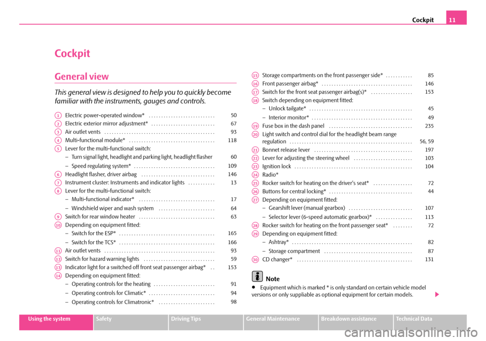
This general view is designed to help you to quickly become
familiar with the instruments, gauges and controls.
Electric power-operated window* . . . . . . . . . . . . . . . . . . . . . . . . . . .
Electric exterior mirror adjustment* . . . . . . . . . . . . . . . . . . . . . . . . . .
Air outlet vents . . . . . . . . . . . . . . . . . . . . . . . . . . . . . . . . . . . . . . . . . . . . .
Multi-functional module* . . . . . . . . . . . . . . . . . . . . . . . . . . . . . . . . . . .
Lever for the multi-functional switch:
− Turn signal light, headlight and parking light, headlight flasher
− Speed regulating system* . . . . . . . . . . . . . . . . . . . . . . . . . . . . . . . . .
Headlight flasher, driver airbag . . . . . . . . . . . . . . . . . . . . . . . . . . . . . .
Instrument cluster: Instruments and indicator lights . . . . . . . . . . .
Lever for the multi-functional switch:
− Multi-functional indicator* . . . . . . . . . . . . . . . . . . . . . . . . . . . . . . .
− Windshield wiper and wash system . . . . . . . . . . . . . . . . . . . . . . .
Switch for rear window heater . . . . . . . . . . . . . . . . . . . . . . . . . . . . . . .
Depending on equipment fitted:
− Switch for the ESP* . . . . . . . . . . . . . . . . . . . . . . . . . . . . . . . . . . . . . . .
− Switch for the TCS* . . . . . . . . . . . . . . . . . . . . . . . . . . . . . . . . . . . . . . .
Air outlet vents . . . . . . . . . . . . . . . . . . . . . . . . . . . . . . . . . . . . . . . . . . . . .
Switch for hazard warning lights . . . . . . . . . . . . . . . . . . . . . . . . . . . . .
Indicator light for a switched off front seat passenger airbag* . .
Depending on equipment fitted:
− Operating controls for the heating . . . . . . . . . . . . . . . . . . . . . . . . .
− Operating controls for Climatic* . . . . . . . . . . . . . . . . . . . . . . . . . . .
− Operating controls for Climatronic* . . . . . . . . . . . . . . . . . . . . . . .
Storage compartments on the front passenger side* . . . . . . . . . . .
Front passenger airbag* . . . . . . . . . . . . . . . . . . . . . . . . . . . . . . . . . . . . .
Switch for the front seat passenger airbag(s)* . . . . . . . . . . . . . . . . .
Switch depending on equipment fitted:
− Unlock tailgate* . . . . . . . . . . . . . . . . . . . . . . . . . . . . . . . . . . . . . . . . . .
− Interior monitor* . . . . . . . . . . . . . . . . . . . . . . . . . . . . . . . . . . . . . . . . .
Fuse box in the dash panel . . . . . . . . . . . . . . . . . . . . . . . . . . . . . . . . . .
Light switch and control dial for the headlight beam range regulation . . . . . . . . . . . . . . . . . . . . . . . . . . . . . . . . . . . . . . . . . . . . . . . . . .
Bonnet release lever . . . . . . . . . . . . . . . . . . . . . . . . . . . . . . . . . . . . . . . .
Lever for adjusting the steering wheel . . . . . . . . . . . . . . . . . . . . . . . .
Ignition lock . . . . . . . . . . . . . . . . . . . . . . . . . . . . . . . . . . . . . . . . . . . . . . . .
Radio*
Rocker switch for heating on the driver's seat* . . . . . . . . . . . . . . . .
Buttons for central locking* . . . . . . . . . . . . . . . . . . . . . . . . . . . . . . . . . .
Depending on equipment fitted:
− Gearshift lever (manual gearbox) . . . . . . . . . . . . . . . . . . . . . . . . . .
− Selector lever (6-speed automatic gearbox)* . . . . . . . . . . . . . . .
Rocker switch for heating on the front passenger seat* . . . . . . . .
Depending on equipment fitted:
− Ashtray* . . . . . . . . . . . . . . . . . . . . . . . . . . . . . . . . . . . . . . . . . . . . . . . . .
− Storage compartment . . . . . . . . . . . . . . . . . . . . . . . . . . . . . . . . . . . .
CD changer* . . . . . . . . . . . . . . . . . . . . . . . . . . . . . . . . . . . . . . . . . . . . . . .
Note
•Equipment which is marked * is only standard on certain vehicle model versions or only suppliable as opti onal equipment for certain models.
A150
A267
A393
A4118
A5
60
109
A6146
A713
A8
17
64
A963
A10
165
166
A1193
A1259
A13153
A14
91
94
98
A1585
A16146
A17153
A18
45
49
A19235
A2056, 59
A21197
A22103
A23104
A24
A2572
A2644
A27
107
113
A2872
A29
82
87
A30131
NKO A05Fabia 20.book Page 11 Tuesday, September 26, 2006 8:38 AM
Page 14 of 258
Instruments and Indicator/Warning Lights13
Using the systemSafetyDriving TipsGeneral MaintenanceBreakdown assistanceTechnical Data
Instruments and Indicator/Warning Lights
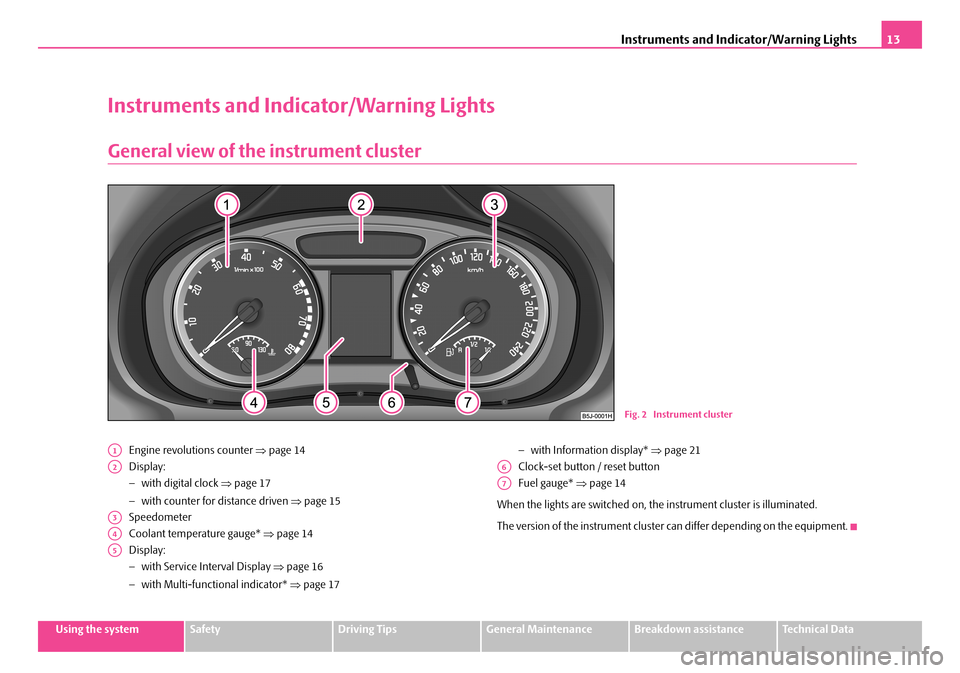
General view of the instrument cluster
Engine revolutions counter ⇒page 14
Display:
− with digital clock ⇒page 17
− with counter for distance driven ⇒page 15
Speedometer
Coolant temperature gauge* ⇒page 14
Display:
− with Service Interval Display ⇒page 16
− with Multi-functional indicator* ⇒page 17
− with Information display* ⇒page 21
Clock-set button / reset button
Fuel gauge* ⇒page 14
When the lights are switched on, th e instrument cluster is illuminated.
The version of the instrument cluster can differ depending on the equipment.
Fig. 2 Instrument cluster
A1
A2
A3
A4
A5
A6
A7
NKO A05Fabia 20.book Page 13 Tuesday, September 26, 2006 8:38 AM
Page 16 of 258
Instruments and Indicator/Warning Lights15
Using the systemSafetyDriving TipsGeneral MaintenanceBreakdown assistanceTechnical Data
The fuel tank has a capacity of ab out 55 litres. The warning symbol in the instrument cluster lights up when th e pointer reaches the reserve marking. There are now about 7 litres of fuel remaining in the tank. This symbol is a reminder for you, that you must refuel.
The following will be displayed in the information display*:
PLEASE REFUEL
A peep sounds as an additional warning signal.
Caution
Never run the fuel tank completely empty! An irregular fuel supply can result in poor ignition or misfiring. Unburnt fuel may get into the exhaust system and damage the catalytic converter.
Counter for distance driven
The distance which you have driven with your vehicle is shown in kilometres (km). On certain model versions, the readout is shown in “miles”.
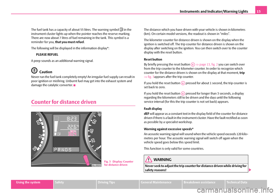
The kilometer counter for distance driven is shown on the display when the ignition is switched off. The trip count er for distance driven is shown on the display after switching on the ignition. Yo u can then switch over to the counter display with the reset button.
Reset button
By briefly pressing the reset button ⇒page 13, fig. 2 you can switch over from the trip counter to the kilomete r counter. In order to recognize which counter for the distance driven is shown on the display at that moment, trip ⇒ fig. 3appears after the trip counter.
If you hold the reset button pressed fo r about 1 second, the trip counter is set back to zero.
If you hold the reset button pressed for longer than 3 seconds, a display regarding the kilometers still to be driven and the days until the following service interval (for this the trip counter is not set back) appears.
Fa u l t d i s p l a y
dEF will appear as a constant text in the display field of the counter for distance driven if there is a fault in the instrument cluster. Have the fault rectified as soon as possible by a specialist workshop.
Warning against excessive speeds*
An acoustic warning signal will sound wh en the vehicle speed exceeds 120 kilo- metres per hour. The acoustic warning si gnal will switch off again when the vehicle speed goes below this speed limit.
This function is only valid for some countries.
WARNING
Never seek to adjust the trip counter for distance driven while driving for safety reasons!
Fig. 3 Display: Counter for distance driven
A6
A6
A6
NKO A05Fabia 20.book Page 15 Tuesday, September 26, 2006 8:38 AM
Page 18 of 258
Instruments and Indicator/Warning Lights17
Using the systemSafetyDriving TipsGeneral MaintenanceBreakdown assistanceTechnical Data
•affix the sticker with the entry of the following service interval to the side of the dash panel on the driver's side.
The Service Interval Display can also be reset with the reset button as follows:
•Switch off the ignition, press the reset button of the trip counter for distance driven and hold it down.
•Switch the ignition on and release the reset button. Now turn the reset button to the right. The service interval display is reset.
Caution
We recommend that you do not reset th e Service Interval Display yourself otherwise this can result in the service interval display being incorrectly set, which may also result in problems with operation of your vehicle.
Note
•Never reset the display between service intervals otherwise this may result in incorrect readouts.
•information is retained in the Service Interval Display also after the battery of the vehicle is disconnected.
•it is necessary to re-code the Servic e Interval Display if a new instrument cluster is installed during repair work. Th is work is carried out by a specialist garage.
•The data displayed is the same after resetting the display with flexible service intervals (QG1) using the reset button as that for a vehicle with fixed service intervals (QG2). We therefore recommend having the Service Interval Display reset only by a Škoda Service Partner who is familiar with the procedure for resetting the display with a vehicle system tester.
•Please refer to the brochure Service schedule for extensive information about the service intervals.
Digital clock
A reset button is installed on the left below beside the speedometer
for adjusting the clock ⇒page 13, fig. 2.
Set hours
– Turn the reset button to the left.
Setting minutes
– Turn the reset button to the right.
WARNING
The clock should not be adjusted while driving for safety reasons but only when the vehicle is stationary.
Multi-functional indicator (onboard
computer)*
Introduction
The multi-functional indicator appears in the display ⇒page 18, fig. 5 or in the information display ⇒page 21, fig. 8 depending on the equipment fitted to your vehicle.
The multi-functional indicator offers you a range of useful information.
A6
NKO A05Fabia 20.book Page 17 Tuesday, September 26, 2006 8:38 AM
Page 20 of 258

Instruments and Indicator/Warning Lights19
Using the systemSafetyDriving TipsGeneral MaintenanceBreakdown assistanceTechnical Data
Using the system
The rocker switch and the button are located in the grip of the
window wiper lever ⇒fig. 6.
Selecting the memory
– Repeated short-term pressing of the button allows one to
select the individual memories.
Selecting the functions
– Press the rocker switch up or down. This will cause the indi-
vidual functions of the multi-functi onal indicator to appear in the
display one after the other.
Setting function to zero
– Select the memory you want.
– Press button for more than 1 second.
The following readouts of the selected memory will be set to zero by button :
•average fuel consumption,
•distance driven,
•average speed,
•Driving time.
You can only operate the multi-functional indicator when the ignition is switched on. After the ignition is switched on, the function displayed is the one which you last selected before switching off the ignition.
If the outside temperature drops below +4 °C, a snow flake symbol (warning signal for ice on the road) appears with the outside temperature indicator ⇒ fig. 7 and a warning signal* sounds for 10 seconds. The snoke flake symbol draws the attention of the driver to possible black ice formation. The display swicthes back after 10 seconds to the last selected function.
Outside temperature
Fig. 6 Multi-functional indicator: Control elements
AAAB
AB
AA
AB
AB
Fig. 7 Multi-functional indicator: the outside temperature
NKO A05Fabia 20.book Page 19 Tuesday, September 26, 2006 8:38 AM
Page 22 of 258
Instruments and Indicator/Warning Lights21
Using the systemSafetyDriving TipsGeneral MaintenanceBreakdown assistanceTechnical Data
Driving time
The driving time which has elapsed since the memory was last erased, appears in the display ⇒page 18. If you wish to calculate the driving time from a partic- ular time of day you must first erase th e memory at this moment in time by pressing the button ⇒page 19, fig. 6.
The maximum time indicated in both switch positions is 99 hours and 59 minutes. The indicator is set back to null if this period is exceeded.
Distance driven
The distance driven since the memory was last erased appears in the display ⇒ page 18. If you wish to calculate the distance driven from a particular time of day you must first erase the memory at this moment in time by pressing the button ⇒page 19, fig. 6.
The maximum distance indicated in both switch positions is 9999 km. The indi- cator is set back to null if this period is exceeded.
Average speed
The average speed since the memory was last erased is shown in the display in km/hour ⇒page 18. If you wish to determine the average speed over a certain period of time you must first erase the memory at the start of the new measure- ment using the button ⇒page 19, fig. 6.
A zero appears in the display for the first 100 m you drive after erasing the memory.
Information display*
Introduction
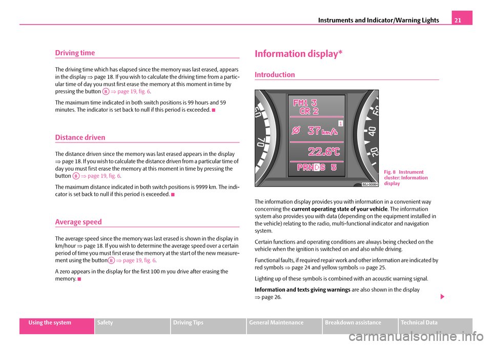
The information display provides you wi th information in a convenient way concerning the current operating state of your vehicle. The information system also provides you with data (depending on the equipment installed in the vehicle) relating to the radio, multi-functional indicator and navigation system.
Certain functions and operating conditio ns are always being checked on the vehicle when the ignition is switched on and also while driving.
Functional faults, if required repair wo rk and other information are indicated by red symbols ⇒page 24 and yellow symbols ⇒page 25.
Lighting up of these symbols is combin ed with an acoustic warning signal.
Information and texts giving warnings are also shown in the display ⇒ page 26.
AB
AB
AB
Fig. 8 Instrument cluster: Information display
NKO A05Fabia 20.book Page 21 Tuesday, September 26, 2006 8:38 AM