technical data SKODA FABIA 2007 1.G / 6Y Owner's Guide
[x] Cancel search | Manufacturer: SKODA, Model Year: 2007, Model line: FABIA, Model: SKODA FABIA 2007 1.G / 6YPages: 242, PDF Size: 48.29 MB
Page 64 of 242

Seats and Stowage63
Using the systemSafetyDriving TipsGeneral MaintenanceBreakdown assistanceTechnical Data
The luggage compartment cover
You can use the luggage compartment cover behind the head
restraints for storing light and soft items.
The luggage compartment cover can be removed as required if one must
transport bulky goods.
– Unhook the support stra ps on the boot lid ⇒page 63, fig. 58.
– Slightly raise the luggage compartment cover.
– Remove the luggage compartment cover from the holders by
pulling to the rear or with adequate blows to the bottom side of the
luggage compartment cover in the area between the holders.
– To re-install, place the luggage compartment cover on the contact
surfaces of the side trim panels and press the luggage compartment
cover into the holders by pushing forward and then hang the
support straps on the tailgate.
The luggage compartment cover in the uppe r position is foreseen for storage of small objects of up to 2.5 kg. in weight.
Caution
Please ensure that the heating elements of the rear window heater are not damaged as a result of obje cts placed in this area.
Note
When opening the boot lid, lift the luggage compartment cover - risk that objects placed in this area can slip forward!
Further positions of the luggage compartment cover
You can use the luggage compar tment cover behind the head
restraints for storing light and soft items.Fig. 58 Removing the luggage compartment cover
A1
A2
A2
A1
Fig. 59 Luggage compartment cover in the lower position
Fig. 60 Luggage compartment cover stowed behind the rear seats.
NKO A05F 20 MR08.book Page 63 Thursday, April 19, 2007 11:34 AM
Page 66 of 242

Seats and Stowage65
Using the systemSafetyDriving TipsGeneral MaintenanceBreakdown assistanceTechnical Data
Fitting
– Insert the attachment points of th e roof rack into the mounts of the
body so that the pins of the attachment points grasp into the holes of
the body.
Note
•Pay attention to the information regarding assembly and disassembly in the attached instructions.
•If you have any questions, plea se contact a specialist garage.
Roof load
Distribute weight evenly over the roof luggage rack system. The maximum permis- sible roof load (including roof rack system) of 75 kg and the maximum permissible total weight of the vehicle should not be exceeded.
You cannot make full use of the permissible roof load if you use a roof luggage rack system with a lower load carrying capacity. The load transported on the roof luggage rack system must not exceed the we ight limit which is stated in the fitting instructions.
WARNING
•The items which you transport on the roof bar system must be reliably attached - risk of accident!
•You must on no account exceed the permissible roof load, the permis- sible axle loads and the permissible gros s weight of your vehicle - risk of accident!
•Please note that the handling prop erties of your vehicle change when you transport heavy or bulky items on the roof bar system as a result of the displacement of the centre of gravity and the increased wind attack area - risk of accident! You must absolutely adapt your style of driving and the speed of the vehicle to the specific circumstances.
Front cup holder
You can place two cups or beve rage cans into the recesses ⇒fig. 62.
WARNING
•Do not place any hot beverages into the cup holder. If the vehicle moves, the hot beverages may spill - risk of scalding!
•Do not use any cups or beakers which are made of brittle material (e.g. glass, porcelain). You might be injured by them in the event of an accident.
Caution
Do not open the beverages in the cup holder while driving. There is a risk of spilling e.g. when braking and therefore the electrical components or the seat upholstery can be damaged.
Fig. 62 Front centre console: Cup holder
NKO A05F 20 MR08.book Page 65 Thursday, April 19, 2007 11:34 AM
Page 68 of 242

Seats and Stowage67
Using the systemSafetyDriving TipsGeneral MaintenanceBreakdown assistanceTechnical Data
Ashtray*
Removing ashtray
– Remove the ashtray ⇒fig. 65 upwards. When removing do not hold
the ashtray at the cover - risk of breakage.
Replacing ashtray
– Insert the ashtray vertically.
WARNING
Never lay flammable objects in the ashtray basin - risk of fire!
Cigarette lighter* and power sockets*
Cigarette lighter
You can also use the socket on the cigarette lighter for other elec-
trical appliances.
Using the cigarette lighter
– Press in the button of the cigarette lighter ⇒fig. 67.
– Wait until the button jumps forward.
– Remove the cigarette lighter immediately and use it.
– Insert the cigarette lighter again into the socket.
Using the power socket
– Take out the cigarette lighter.
– Insert the plug of the electrical a ppliance into the socket of the ciga-
rette lighter.
The 12 volt power socket can also be used to supply power to electrical accessories with a power uptake up to 180 watts.
Fig. 65 Centre console: Front ashtray
Fig. 66 Centre console: Rear ashtray
Fig. 67 Centre console: Cigarette lighter
NKO A05F 20 MR08.book Page 67 Thursday, April 19, 2007 11:34 AM
Page 70 of 242
Seats and Stowage69
Using the systemSafetyDriving TipsGeneral MaintenanceBreakdown assistanceTechnical Data
Opening and closing the storage compartments on the front
passenger side
– Pull or press the handle of the lid in the direction of arrow ⇒page 68,
fig. 68 and fold open the lid.
– Raise the lid until it is heard to engage.
A pin holder is located inside the lid.
WARNING
The storage compartment must always be closed when driving for safety reasons.
Cooling of storage compartment on front passenger side*
The storage compartment can be fitted for vehicles with an air-
conditioning system with a closable inlet for cooled air.
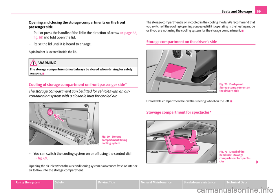
– You can switch the cooling system on or off using the control dial
⇒ fig. 69.
Opening the air inlet when the air conditioning system is on causes fresh or interior air to flow into the storage compartment.
The storage compartment is only cooled in the cooling mode. We recommend that you switch off the cooling (opening concealed) if it is operating in the heating mode or if you are not using the cooling system for the storage compartment.
Storage compartment on the driver's side
Unlockable compartment below the steering wheel on the left.
Stowage compartment for spectacles*
Fig. 69 Storage compartment: Using cooling system
Fig. 70 Dash panel: Storage compartment on the driver's side
Fig. 71 Detail of the headliner: Stowage compartment for specta-cles
NKO A05F 20 MR08.book Page 69 Thursday, April 19, 2007 11:34 AM
Page 72 of 242

Seats and Stowage71
Using the systemSafetyDriving TipsGeneral MaintenanceBreakdown assistanceTechnical Data
Front seat armrest with storage compartment*
Fold the armrest
– Press the lower button on the end face of the armrest ⇒fig. 74 in
order to fold the armrest. Fold th e armrest forwards and release the
button.
Opening stowage compartment
– The armrest includes a stowage compartment. The storage compart-
ment is unlocked by pressing the upper button and then can be
opened to the top.
Note
The moving space of the arms can be restricted if the armrest is folded down. In city traffic the armrest should not be folded down.
Storage compartment in the front doors
A bottle holder is located in the area of the storage compartment for the front doors.
WARNING
Use the area ⇒fig. 76 of the storage compartment only for storing objects which do not project so that the effectiveness of the side airbag is not impaired.
Fig. 74 Armrest: Storage compartment
Fig. 75 Opening stowage compartment
Fig. 76 Stowage compartment in door panel
AB
AA
NKO A05F 20 MR08.book Page 71 Thursday, April 19, 2007 11:34 AM
Page 74 of 242

Seats and Stowage73
Using the systemSafetyDriving TipsGeneral MaintenanceBreakdown assistanceTechnical Data
Removeable storage compartments in the luggage
compartment*
A removeable storage compartment*⇒fig. 79 is located on both sides in the side trim panel of the luggage compartment.
The removeable storage compartments* are intended for storing small objects of up to 2.5 kg in weight.
Flexible storage compartment*
A flexible storage compartment is located on the right side of the luggage
compartment. The flexible storage co mpartment is foreseen for storing
small objects of up to 8 kg. in weight.
Removing
– Take hold of the flexible storage compartment at both upper corners.
– Press the upper corners to the inside and release the storage compart-
ment by pulling upwards.
– Remove by pulling towards you.
Installing
– Insert both ends of the flexible storage compartment into the open-
ings of the right side trim panel of the luggage compartment and push
it downwards until it locks.
Clothes hooks*
A clothes hook is located above the rear doors ⇒fig. 81.
Fig. 79 Removeable storage compartments
Fig. 80 Flexible storage compartment
Fig. 81 Area above rear doors: Clothes hooks
NKO A05F 20 MR08.book Page 73 Thursday, April 19, 2007 11:34 AM
Page 76 of 242
Heating and air conditioning system75
Using the systemSafetyDriving TipsGeneral MaintenanceBreakdown assistanceTechnical Data
Heating and air conditioning system
Heating
Using the system
The heating system delivers air into the interior of the vehicle and
warms it as required.
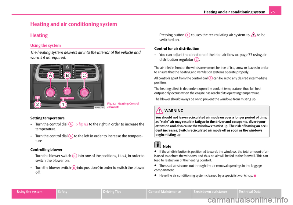
Setting temperature
– Turn the control dial ⇒fig. 82 to the right in order to increase the
temperature.
– Turn the control dial to the left in order to increase the tempera-
ture.
Controlling blower
– Turn the blower switch into one of the positions, 1 to 4, in order to
switch the blower on.
– Turn the blower switch into position 0 in order to switch the blower
off.
– Pressing button causes the recirculating air system ⇒ to be
switched on.
Control for air distribution
– You can adjust the direction of the inlet air flow ⇒page 77 using air
distribution regulator .
The air inlet in front of the windscreen must be free of ice, snow or leaves in order to ensure that the heating and ventilation systems operate properly.
All controls apart from the control dial can be set to any desired intermediate position.
The heating effect is dependent upon th e coolant temperature, thus full heat output only occurs when the engine has reached its operating temperature.
The blower should aways be on to prevent the windows from misting up.
WARNING
You should not leave recirculated air mode on over a longer period of time, as “stale” air may result in fatigue in the driver and occupants, divert your attention and also cause the windows to mist up. The risk of having an acci- dent increases. Switch recirculated air mode off as soon as the windows begin misting up.
Note
•If the air distribution is positioned towa rds the windows, the total amount of air is used to defrost the window s and thus no air will be fed to the footwell. This can lead to restriction of the heating comfort.
•The used air streams out through the air removal openings in the luggage compartment.
•Have the air conditioning system cleaned by a specialist workshop.
Fig. 82 Heating: Control elements
AA
AA
AB
AB
A1
AC
AB
NKO A05F 20 MR08.book Page 75 Thursday, April 19, 2007 11:34 AM
Page 78 of 242
Heating and air conditioning system77
Using the systemSafetyDriving TipsGeneral MaintenanceBreakdown assistanceTechnical Data
WARNING
You should not leave recirculated air mode on over a longer period of time, as “stale” air may result in fatigue in the driver and occupants, divert your attention and also cause the windows to mist up. The risk of having an acci- dent increases. Switch recirculated air mode off as soon as the windows begin misting up.
Air outlet vents
Fig. 83 Air outlet vents
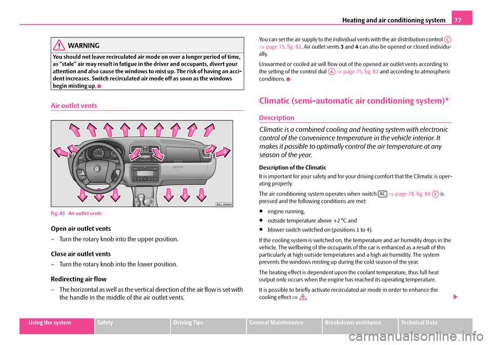
Open air outlet vents
– Turn the rotary knob in to the upper position.
Close air outlet vents
– Turn the rotary knob into the lower position.
Redirecting air flow
– The horizontal as well as the vertical direction of the air flow is set with
the handle in the middle of the air outlet vents.
You can set the air supply to the individual vents with the air distribution control ⇒ page 75, fig. 82. Air outlet vents 3 and 4 can also be opened or closed individu- ally.
Unwarmed or cooled air will flow out of the opened air outlet vents according to the setting of the control dial ⇒page 75, fig. 82 and according to atmospheric conditions.
Climatic (semi-automatic air conditioning system)*
Description
Climatic is a combined cooling and heating system with electronic
control of the convenience temperat ure in the vehicle interior. It
makes it possible to optimally control the air temperature at any
season of the year.
Description of the Climatic
It is important for your safety and for your driving comfort that the Climatic is oper- ating properly.
The air conditioning system operates when switch ⇒page 78, fig. 84 is pressed and the following conditions are met:
•engine running,
•outside temperature above +2 °C and
•blower switch switched on (positions 1 to 4).
If the cooling system is switched on, th e temperature and air humidity drops in the vehicle. The wellbeing of the occupants of the car is enhanced as a result of this particularly at high outside temperatur es and a high air humidity. The system prevents the windows misting up during the cold season of the year.
The heating effect is dependent upon th e coolant temperature, thus full heat output only occurs when the engine has reached its operating temperature.
It is possible to briefly activate recirc ulated air mode in order to enhance the cooling effect ⇒.
AC
AA
ACAE
NKO A05F 20 MR08.book Page 77 Thursday, April 19, 2007 11:34 AM
Page 80 of 242
Heating and air conditioning system79
Using the systemSafetyDriving TipsGeneral MaintenanceBreakdown assistanceTechnical Data
switching cooling on and off
– Press the button . The symbol in the switch comes on.
– When you again press the switch , the cooling system is switched
off. The symbol in the button is no longer illuminated.
The set temperature will be automatically maintained other than when the control dial is on the extreme right or extreme left position:
Extreme right position - full heating.
Extreme left position - full cooling.
The controls and can be set to any desired intermediate position.
The blower should aways be on to prevent the windows from misting up.
Note
•The whole heat output will be needed to unfrost the windscreen and side windows. No warm air will be fed to the f ootwell. This can lead to restriction of the heating comfort.
•The used air streams out through the air removal openings in the luggage compartment.
•If the cooling system has not been switched on for a lengthy period, odours may be produced at the evaporator because of deposits. Switch the air conditioning system on at least once a month for appr oximately 5 minutes at the highest blower stage - also during the cold season of the year - in order to remove such odours. Also open a window for a short time.
•Please refer to the information regarding recirculated air mode ⇒page 80.
•Have the air conditioning system cleaned by a specialist workshop.
Set Climatic
Recommended settings of Climatic controls for the respective operating modes:
Defrosting the windscreen and side windows
•Put the control dial ⇒page 78, fig. 84 to the temperature selected as usual by you (we recommend 22 °C)
•Blower switch in position 3 or 4
•Turn the air distribution control into the position
•Open air outlet vents 4 ⇒page 80, fig. 85 and point towards the side window.
Keeping windscreen and side windows demisted
We recommend that you use the following setting in cases where the windows are misted up more than usual (e.g. when it is raining):
•Blower switch in position 2
•Turn the air distribution control into the position between and
•Open air outlet vents 4 ⇒page 80, fig. 85 and point towards the side window.
•Switch on the cooling system by pressing button .
Warming up the inside of the vehicle as rapidly as possible
•Control dial at the desired heat temperature
•Blower switch in position 3
•Turn the air distribution control into the position
•Open the air outlet vents 4
•We recommend that you briefly switch on the recirculated air mode with the pushbutton . The windows can steam up in this position however.
Heating the vehicle to a comfortable temperature
We recommend the following setting once the windows are no longer misted up and the desired temperature has been reached:
•Control dial at the desired heat temperature
•Blower switch in position 2
•Turn the air distribution control into the position between and
•Open the air outlet vents 4
•Set the air distribution regulator as required between positions and , if the windscreen gets misted up again.
AC
AC
AAAC
AA
AB
AC
AB
AC
AC
AA
AB
AC
AA
AB
AC
AC
NKO A05F 20 MR08.book Page 79 Thursday, April 19, 2007 11:34 AM
Page 82 of 242
Heating and air conditioning system81
Using the systemSafetyDriving TipsGeneral MaintenanceBreakdown assistanceTechnical Data
Close air outlet vents
– Turn the rotary knob into the lower position.
Redirecting air flow
– The horizontal as well as the vertical direction of the air flow is set with
the handle in the middle of the air outlet vents.
You can set the air supply to the individual vents with the air distribution control ⇒ page 78, fig. 84. Air outlet vents 3 and 4 can also be opened or closed individu- ally:
Unwarmed or cooled air will flow out of th e air outlet vents according to the setting of control dial ⇒page 78, fig. 84 and the atmospheric conditions.
Using the air conditioning system economically
The compressor on the Climatic uses power from the engine when in cooling mode which will effect the fuel consumption.
It recommended to open the windows or th e doors of a vehicle for which the inte- rior has been strongly heated through the ef fect of direct sunlight in order to allow the heated air to escape.
The cooling system should not be switched on while travelling when the window is open.
The desired interior temperature can also be achieved without switching in the cooling system just by switching to fresh air mode.
For the sake of the environment
When you economize on fuel, you also reduce pollutant emissions.
Operational problems
If the cooling system does not operate at outside temperatures higher than +2 °C, there is a problem in the system. The reasons for this may be:
•The fuse of the Climatic is defective. Check the fuse, replace it if necessary ⇒ page 205.
•The cooling system has switched off automatically for a short time because the coolant temperature of the engine is too hot ⇒page 10.
If you are not able to rectify the operat ional problem yourself, or if the cooling capacity decreases, switch the cooling sy stem off. Contact a specialist garage.
If there is a fault at the Climatronic, all symbols on the display flash after switching on the ignition for 15 seconds. Contact a specialist garage.
Climatronic (automatic air conditioning)*
Description
The Climatronic system is a comb ination of an automatic heating,
fresh air and cooling system which provides optimal comfort for the
occupants of the car.
The Climatronic maintains a constant temper ature fully automatically, once it has been set. This is achieved by automa tically varying the temperature of the outflowing air, the blower stages and the ai r distribution. The system also takes into account sunlight which eliminates the n eed to alter the settings manually. The automatic mode ⇒page 83 ensures maximum wellbeing of the occupants at all times of the year.
Description of Climatronic system
The cooling operates only if the following conditions are met:
•engine running,
•outside temperature above +2 °C,
•the button is not pressed.
If the cooling system is switched on, th e temperature and air humidity drops in the vehicle. The wellbeing of the occupants of the car is enhanced as a result of this particularly at high outside temperatur es and a high air humidity. The system prevents the windows misting up during the cold season of the year.
AC
AA
ECON
NKO A05F 20 MR08.book Page 81 Thursday, April 19, 2007 11:34 AM