technical data SKODA FABIA 2007 1.G / 6Y Owner's Manual
[x] Cancel search | Manufacturer: SKODA, Model Year: 2007, Model line: FABIA, Model: SKODA FABIA 2007 1.G / 6YPages: 242, PDF Size: 48.29 MB
Page 3 of 242
Introduction2
On-board literature
The on-board literature for your vehicle consists of this “ Owner's
Manual ” as well as the brochures “Service schedule”, “Brief instruc-
tion ”, “Technical data” and “Help on the road”. There can also be a
variety of other additional operatin g manuals and instructions on-board
(e.g. an operating manual for the radio) depending on the vehicle model
and equipment.
If one of the publications listed above is missing, please contact a Škoda
Service Partner immediately, where one wi ll be glad to assist you in such
matters.
One should note that the details give n in the vehicle's papers always
take precedence over those in the Owner's Manual.
Owner's Manual
This Owner's Manual describes the current scope of equipment.
Certain items of equipment listed ar e only installed later on and only
envisaged for particular markets. The illustrations can differ in minor
details from your vehicle; they are only intended for general information.
In addition to information regarding all the controls and equipment, the
Owner's Manual also contains import ant information regarding care and
operation for your safety and also to retain the value of your vehicle. To
provide you with valuable tips and aids. You can learn how how you can
operate your vehicle safely, economically and in an environmentally
conscious way.
For safety reasons, please also pay attention to the information on
accessories, modifications and replacement of parts .
The other chapters of the Owner's Manual are also important, however,
for proper treatment of your car - in addition to regular care and mainte-
nance - helps to retain its value and in many cases is also one of the
conditions for possible warranty claims.
The Brief instruction
includes an overview of the most important controls of your vehicle.
The Service schedule
contains:
•vehicle data,
•service intervals,
•overview of the service work,
•service proof,
•confirmation of mobility warranty,
•important information on the warranty.
The confirmations of the carried out service work are one of the condi-
tions for possible warranty claims.
Please always present th e Service schedule when you take your car to a
Škoda Service Partner.
If the Service schedule is missing or worn, please contact your Škoda
Service Partner, where your car is serviced regularly. You will receive a
duplicate, in which the previously carried out service work are confirmed.
Help on the road
contains the addresses and telephone numbers of Škoda Importers.
Technical Data
includes the most important identi fication data of your vehicle.
NKO A05F 20 MR08.book Page 2 Thursday, April 19, 2007 11:34 AM
Page 5 of 242
Contents4
Head airbags* . . . . . . . . . . . . . . . . . . . . . . . . . . . . . . . . Deactivating an airbag . . . . . . . . . . . . . . . . . . . . . . . .
Transporting children safely . . . . . . . . . . . . . . . . . . What you should know about transporting children! Child seat . . . . . . . . . . . . . . . . . . . . . . . . . . . . . . . . . . . . Attaching a child seat using the “ISOFIX” system*Attaching child seat using the “Top Tether” system
Driving Tips. . . . . . . . . . . . . . . . . . . . . . . . . . . . . .
Intelligent Technology . . . . . . . . . . . . . . . . . . . . . . . . Electronic stability programme (ESP)* . . . . . . . . . . Brakes . . . . . . . . . . . . . . . . . . . . . . . . . . . . . . . . . . . . . . . Brake booster . . . . . . . . . . . . . . . . . . . . . . . . . . . . . . . . Antilock brake system (ABS)* . . . . . . . . . . . . . . . . . . Brake Assist* . . . . . . . . . . . . . . . . . . . . . . . . . . . . . . . . . Electrohydraulic power steering . . . . . . . . . . . . . . . Tyre inflation pressure-control system* . . . . . . . . . Diesel particle filter* (diesel engine) . . . . . . . . . . . .
Driving and the Environment. . . . . . . . . . . . . . . . . The first 1 500 kilometres and then afterwards . . Catalytic converter . . . . . . . . . . . . . . . . . . . . . . . . . . . . Driving in an economical and environmentally conscious manner . . . . . . . . . . . . . . . . . . . . . . . . . . . . Environmental compatibility . . . . . . . . . . . . . . . . . . . Motoring abroad . . . . . . . . . . . . . . . . . . . . . . . . . . . . . Avoiding damage to your vehicle . . . . . . . . . . . . . .
To w i n g a t r a i l e r. . . . . . . . . . . . . . . . . . . . . . . . . . . . . . . . Towing a trailer . . . . . . . . . . . . . . . . . . . . . . . . . . . . . . .
General Maintenance. . . . . . . . . . . . . . .
Taking care of your ve hicle and cleaning the vehicle. . . . . . . . . . . . . . . . . . . . . . . . . . . . . . . . . . . . . . . . . General . . . . . . . . . . . . . . . . . . . . . . . . . . . . . . . . . . . . . . Care of the exterior of vehicle . . . . . . . . . . . . . . . . . . Care of the interior of vehicle . . . . . . . . . . . . . . . . . .
Fuel. . . . . . . . . . . . . . . . . . . . . . . . . . . . . . . . . . . . . . . . . . . . Petrol . . . . . . . . . . . . . . . . . . . . . . . . . . . . . . . . . . . . . . . . Diesel . . . . . . . . . . . . . . . . . . . . . . . . . . . . . . . . . . . . . . . .Refuelling . . . . . . . . . . . . . . . . . . . . . . . . . . . . . . . . . . . .
Inspecting and Replenishing. . . . . . . . . . . . . . . . . . Engine compartment . . . . . . . . . . . . . . . . . . . . . . . . . Engine oil . . . . . . . . . . . . . . . . . . . . . . . . . . . . . . . . . . . .Cooling system . . . . . . . . . . . . . . . . . . . . . . . . . . . . . . .Brake fluid . . . . . . . . . . . . . . . . . . . . . . . . . . . . . . . . . . .Battery . . . . . . . . . . . . . . . . . . . . . . . . . . . . . . . . . . . . . . .Windshield washer system . . . . . . . . . . . . . . . . . . . .
Wheels and Tyres. . . . . . . . . . . . . . . . . . . . . . . . . . . . . . Wheels . . . . . . . . . . . . . . . . . . . . . . . . . . . . . . . . . . . . . .
Accessories, changes and replacement of partsAccessories and replacement parts . . . . . . . . . . . . . Technical changes . . . . . . . . . . . . . . . . . . . . . . . . . . . .
Breakdown assistance. . . . . . . . . . . . . .
Breakdown assistance . . . . . . . . . . . . . . . . . . . . . . . . First-aid box* and Warning triangle* . . . . . . . . . . . Fire extinguisher* . . . . . . . . . . . . . . . . . . . . . . . . . . . . .Vehicle tool kit . . . . . . . . . . . . . . . . . . . . . . . . . . . . . . . .Tyre repair kit* . . . . . . . . . . . . . . . . . . . . . . . . . . . . . . . .Spare wheel* . . . . . . . . . . . . . . . . . . . . . . . . . . . . . . . . .Changing a wheel . . . . . . . . . . . . . . . . . . . . . . . . . . . . .Jump-starting . . . . . . . . . . . . . . . . . . . . . . . . . . . . . . . .Tow-starting and towing vehicle . . . . . . . . . . . . . . .
Fuses and light bulbs. . . . . . . . . . . . . . . . . . . . . . . . . . Electric fuses . . . . . . . . . . . . . . . . . . . . . . . . . . . . . . . . . Bulbs . . . . . . . . . . . . . . . . . . . . . . . . . . . . . . . . . . . . . . . .
Technical Data. . . . . . . . . . . . . . . . . . . . . . . . . .
Te c h n i c a l D a t a. . . . . . . . . . . . . . . . . . . . . . . . . . . . . . . . . General comments . . . . . . . . . . . . . . . . . . . . . . . . . . . Used abbreviations . . . . . . . . . . . . . . . . . . . . . . . . . . .
Performances . . . . . . . . . . . . . . . . . . . . . . . . . . . . . . . . . Weight . . . . . . . . . . . . . . . . . . . . . . . . . . . . . . . . . . . . . . .Identification details . . . . . . . . . . . . . . . . . . . . . . . . . .Fuel consumption according to the regulations (99/100/EU) . . . . . . . . . . . . . . . . . . . . . . . . . . . . . . . . . . Dimensions . . . . . . . . . . . . . . . . . . . . . . . . . . . . . . . . . .1.2 ltr./44 kW - EU 4/EU 2DDK . . . . . . . . . . . . . . . . .1.2 ltr./51 kW - EU 4/EU 2DDK . . . . . . . . . . . . . . . . .1.4 ltr./63 kW - EU 4/EU 2DDK . . . . . . . . . . . . . . . . .1.6 ltr./77 kW - EU 4/EU 2DDK . . . . . . . . . . . . . . . . .1.4 ltr./51 kW TDI PD - EU 4 . . . . . . . . . . . . . . . . . . . .1.4 ltr./59 kW TDI PD - EU 4 . . . . . . . . . . . . . . . . . . . .1.9 l/77 kW TDI PD - EU 4 . . . . . . . . . . . . . . . . . . . . . .
Index . . . . . . . . . . . . . . . . . . . . . . . . . . . . . . . . . . . . . . . .
130 131
134 134 137140141
143
143 143 146146147147148148150
151 151 152
152 155156157
158 158
161
161 161 161166
169 169 169170
172 172 175177180181185
186 186
192 192 192
193
193 193 193194194194195200201
205 205 209
215
215 215 215
215 215 215
216 217218220222224226228230
233
NKO A05F 20 MR08.book Page 4 Thursday, April 19, 2007 11:34 AM
Page 10 of 242
Instruments and Indicator/Warning Lights9
Using the systemSafetyDriving TipsGeneral MaintenanceBreakdown assistanceTechnical Data
Instruments and Indicator/Warning Lights
General view of the instrument cluster
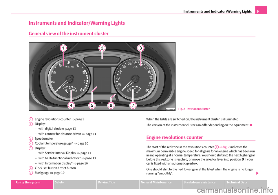
Engine revolutions counter ⇒page 9
Display:
− with digital clock ⇒page 13
− with counter for distance driven ⇒page 11
Speedometer
Coolant temperature gauge* ⇒page 10
Display:
− with Service Interval Display ⇒page 11
− with Multi-functional indicator* ⇒page 13
− with Information display* ⇒page 16
Clock-set button / reset button
Fuel gauge ⇒page 10
When the lights are switched on, the instrument cluster is illuminated.
The version of the instrument cluster can differ depending on the equipment.
Engine revolutions counter
The start of the red zone in the revolutions counter ⇒fig. 2 indicates the maximum permissible engine speed for all gears for an engine which has been run in and operating at a normal temperature. Yo u should shift into the next higher gear before this red zone is reached, or move the selector lever into position D if your car is fitted with an automatic gearbox.
One should shift to the next lower gear at the latest when the engine is no longer running “smoothly”.
Fig. 2 Instrument cluster
A1
A2
A3
A4
A5
A6
A7
A1
NKO A05F 20 MR08.book Page 9 Thursday, April 19, 2007 11:34 AM
Page 12 of 242
Instruments and Indicator/Warning Lights11
Using the systemSafetyDriving TipsGeneral MaintenanceBreakdown assistanceTechnical Data
Counter for distance driven
The distance which you have driven with your vehicle is shown in kilometres (km). On certain model versions, the readout is shown in “miles”.
The kilometer counter for distance driven is shown on the display when the ignition is switched off. The trip counter for dist ance driven is shown on the display after switching on the ignition. You can then swit ch over to the counter display with the reset button.
Reset button
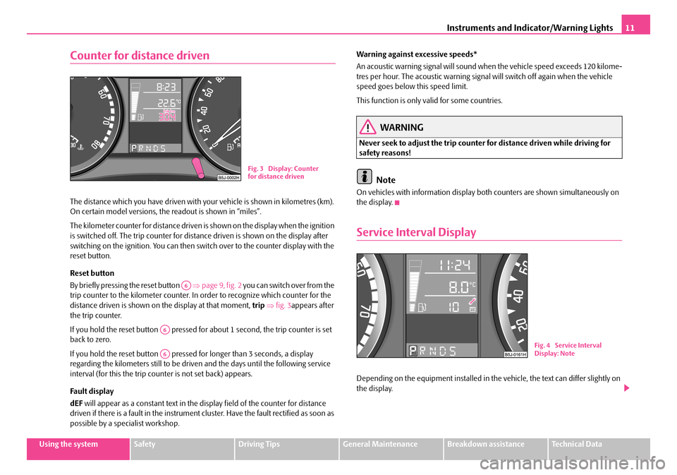
By briefly pressing the reset button ⇒page 9, fig. 2 you can switch over from the trip counter to the kilometer counter. In order to recognize which counter for the distance driven is shown on the display at that moment, trip ⇒fig. 3appears after the trip counter.
If you hold the reset button pressed for about 1 second, the trip counter is set back to zero.
If you hold the reset button pressed for longer than 3 seconds, a display regarding the kilometers still to be driven and the days until the following service interval (for this the trip counter is not set back) appears.
Fa ult di spl a y
dEF will appear as a constant text in the display field of the counter for distance driven if there is a fault in the instrument cluster. Have the fault rectified as soon as possible by a specialist workshop.
Warning against excessive speeds*
An acoustic warning signal will sound when the vehicle speed exceeds 120 kilome- tres per hour. The acoustic warning signal will switch off again when the vehicle speed goes below this speed limit.
This function is only valid for some countries.
WARNING
Never seek to adjust the trip counter for distance driven while driving for safety reasons!
Note
On vehicles with information display bo th counters are shown simultaneously on the display.
Service Interval Display
Depending on the equipment installed in the vehicle, the text can differ slightly on the display.
Fig. 3 Display: Counter for distance driven
A6
A6
A6Fig. 4 Service Interval Display: Note
NKO A05F 20 MR08.book Page 11 Thursday, April 19, 2007 11:34 AM
Page 14 of 242
Instruments and Indicator/Warning Lights13
Using the systemSafetyDriving TipsGeneral MaintenanceBreakdown assistanceTechnical Data
Digital clock
A reset button is installed on the left below beside the speedometer for
adjusting the clock ⇒page 9, fig. 2.
Set hours
– Turn the reset button to the left.
Setting minutes
– Turn the reset button to the right.
WARNING
The clock should not be adjusted while driving for safety reasons but only when the vehicle is stationary.
Multi-functional indicator (onboard computer)*
Introduction
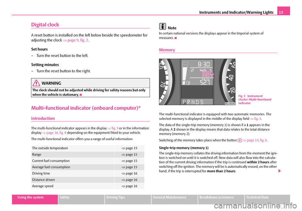
The multi-functional indicator appears in the display ⇒fig. 5 or in the information display ⇒page 16, fig. 8 depending on the equipment fitted to your vehicle.
The multi-functional indicator offers you a range of useful information.
Note
In certain national versions the displays appear in the Imperial system of measures.
Memory
The multi-functional indicator is equi pped with two automatic memories. The selected memory is displayed in the middle of the display field ⇒fig. 5.
The data of the single-trip memo ry (memory 1) is shown if a 1 appears in the display. A 2 shown in the display means that data relates to the total distance memory (memory 2).
Switching of the memory takes place when the button ⇒page 14, fig. 6.
Single-trip memory (memory 1)
The single-trip memory collates the driving information from the moment the igni- tion is switched on until it is switched of f. New data will also flow into the calcula- tion of the current driving information if the trip is continued within 2 hours after switching off the ignition. The memory will be is automatically erased, on the other hand, if the trip is interrupted for more than 2 hours.
The outside temperature⇒page 15
Range⇒page 15
Current fuel consumption⇒page 15
Average fuel consumption⇒page 15
Driving time⇒page 16
Distance driven⇒page 16
Average speed⇒page 16
Fig. 5 Instrument cluster: Multi-functional indicator
AB
NKO A05F 20 MR08.book Page 13 Thursday, April 19, 2007 11:34 AM
Page 16 of 242
Instruments and Indicator/Warning Lights15
Using the systemSafetyDriving TipsGeneral MaintenanceBreakdown assistanceTechnical Data
Outside temperature
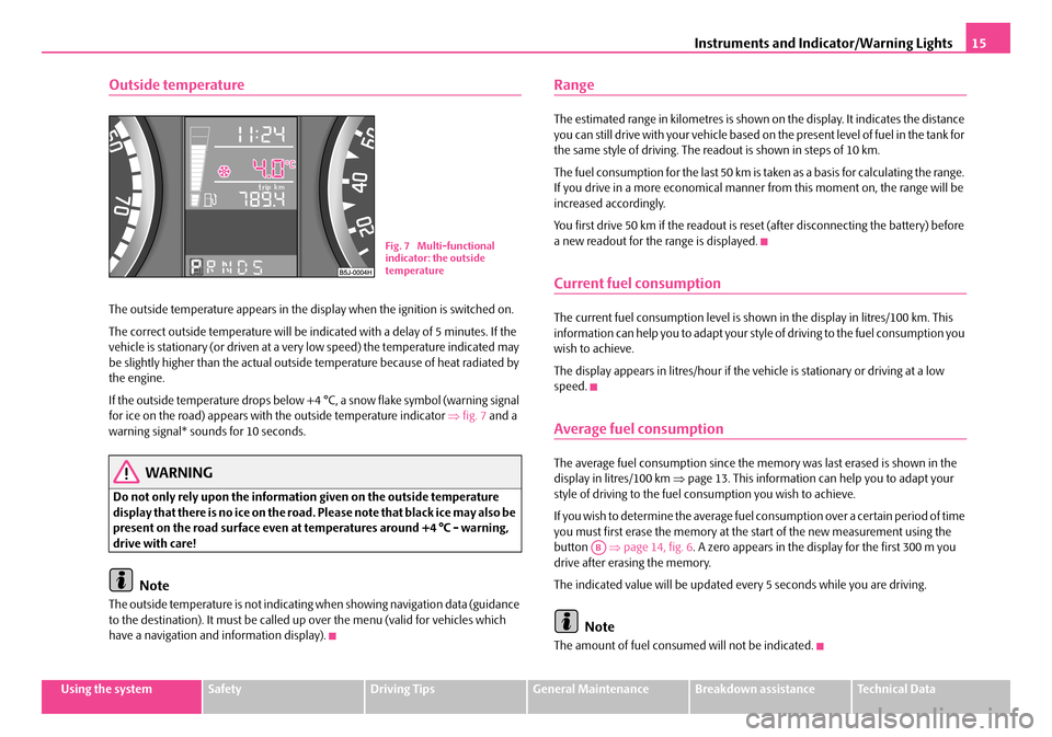
The outside temperature appears in the display when the ignition is switched on.
The correct outside temperature will be indicated with a delay of 5 minutes. If the vehicle is stationary (or driven at a very low speed) the temperature indicated may be slightly higher than the actual outside temperature because of heat radiated by the engine.
If the outside temperature drops below +4 °C, a snow flake symbol (warning signal for ice on the road) appears with the outside temperature indicator ⇒fig. 7 and a warning signal* sounds for 10 seconds.
WARNING
Do not only rely upon the information given on the outside temperature display that there is no ice on the road. Please note that black ice may also be present on the road surface even at temperatures around +4 °C - warning, drive with care!
Note
The outside temperature is not indicating when showing navigation data (guidance to the destination). It must be called up over the menu (valid for vehicles which have a navigation and information display).
Range
The estimated range in kilometres is shown on the display. It indicates the distance you can still drive with your vehicle based on the present level of fuel in the tank for the same style of driving. The readout is shown in steps of 10 km.
The fuel consumption for the last 50 km is taken as a basis for calculating the range. If you drive in a more economical manner from this moment on, the range will be increased accordingly.
You first drive 50 km if the readout is reset (after disconnecting the battery) before a new readout for the range is displayed.
Current fuel consumption
The current fuel consumption level is shown in the display in litres/100 km. This information can help you to adapt your styl e of driving to the fuel consumption you wish to achieve.
The display appears in litres/hour if the vehicle is stationary or driving at a low speed.
Average fuel consumption
The average fuel consumption since the me mory was last erased is shown in the display in litres/100 km ⇒page 13. This information can help you to adapt your style of driving to the fuel co nsumption you wish to achieve.
If you wish to determine the average fuel consumption over a certain period of time you must first erase the memory at the start of the new measurement using the button ⇒page 14, fig. 6. A zero appears in the display for the first 300 m you drive after erasing the memory.
The indicated value will be updated every 5 seconds while you are driving.
Note
The amount of fuel consum ed will not be indicated.
Fig. 7 Multi-functional indicator: the outside temperature
AB
NKO A05F 20 MR08.book Page 15 Thursday, April 19, 2007 11:34 AM
Page 18 of 242
Instruments and Indicator/Warning Lights17
Using the systemSafetyDriving TipsGeneral MaintenanceBreakdown assistanceTechnical Data
Menu
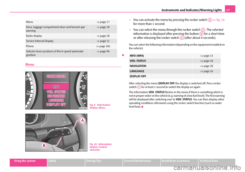
– You can activate the menu by pressing the rocker switch ⇒fig. 10
for more than 1 second.
– You can select the menu through the rocker switch . The selected
information is displayed after pressing the button for a short time
or after releasing the rocker sw itch (after about 4 seconds).
You can select the following information (depending on the equipment installed on the vehicle):
After selecting the menu DISPLAY OFF the display is switched off. Press rocker switch for at least 1 second to switch the display on again.
The Information VEH. STATUS flashes in the menu if there is something which is not in proper order on the vehicle (e.g. warning of a low fuel level). The first warning will be displayed after switching over to VEH. STATUS. You can then display other operating conditions afterwards using the rocker switch function (such as water level low).
Menu⇒ page 17
Door, luggage compartment door and bonnet ajar warning⇒ page 18
Radio display⇒page 18
Service Interval Display⇒page 11
Phone⇒page 101
Selector lever positions of the 6-speed automatic gearbox⇒ page 94
Fig. 9 Information display: Menu
Fig. 10 Information display: Control elements
MFD (MFA)⇒ page 13
VEH. STATUS⇒page 18
NAVIGATION⇒page 20
LANGUAGE⇒page 16
DISPLAY OFF
AA
AA
AB
AA
AA
NKO A05F 20 MR08.book Page 17 Thursday, April 19, 2007 11:34 AM
Page 20 of 242
Instruments and Indicator/Warning Lights19
Using the systemSafetyDriving TipsGeneral MaintenanceBreakdown assistanceTechnical Data
There is at least one error message to be read when the term VEH. STATUS is flashing in the main menu. The display will show STATUS 1/2 (for example) if a number of error messages are displayed. This display indicates that the first of a total of two error messages should be displayed.
Actuate the rocker switch , to call up the individual error messages.
If a fault occurs, a warning signal will also sound in addition to the symbol and text in the display:
•Priority 1 - three warning signals,
•Priority 2 - one warning signal.
Red symbols
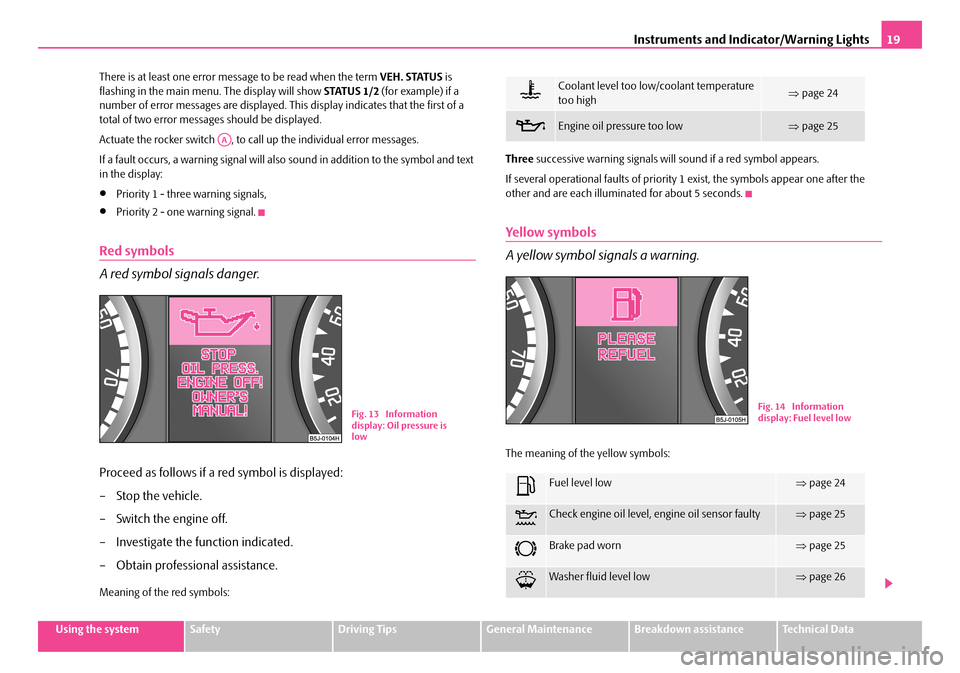
A red symbol signals danger.
Proceed as follows if a red symbol is displayed:
– Stop the vehicle.
– Switch the engine off.
– Investigate the function indicated.
– Obtain professional assistance.
Meaning of the red symbols:
Three successive warning signals will sound if a red symbol appears.
If several operational faults of priority 1 exist, the symbols appear one after the other and are each illumi nated for about 5 seconds.
Yellow symbols
A yellow symbol si gnals a warning.
The meaning of the yellow symbols:
AA
Fig. 13 Information display: Oil pressure is low
Coolant level too low/coolant temperature too high⇒ page 24
Engine oil pressure too low ⇒page 25
Fuel level low⇒page 24
Check engine oil level, engine oil sensor faulty⇒page 25
Brake pad worn⇒page 25
Washer fluid level low⇒page 26
Fig. 14 Information display: Fuel level low
NKO A05F 20 MR08.book Page 19 Thursday, April 19, 2007 11:34 AM
Page 22 of 242
Instruments and Indicator/Warning Lights21
Using the systemSafetyDriving TipsGeneral MaintenanceBreakdown assistanceTechnical Data
WARNING
•If you do not pay attention to the warning lights coming on and the corre- sponding descriptions and warning notes, this may result in severe body injuries or major vehicle damage.
•The engine compartment of your car is a hazardous area. There is a risk of injuries, scalding, accidents and fire when working in the engine
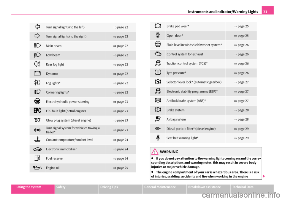
Turn signal lights (to the left)⇒page 22
Turn signal lights (to the right)⇒page 22
Main beam⇒page 22
Low beam⇒page 22
Rear fog light⇒page 22
Dynamo⇒page 22
Fog lights*⇒page 22
Cornering lights*⇒page 22
Electrohydraulic power steering⇒page 23
EPC fault light (petrol engine)⇒page 23
Glow plug system (diesel engine)⇒page 23
Turn signal system for vehicles towing a trailer*⇒ page 23
Coolant temperature/coolant level⇒page 24
Electronic immobiliser⇒page 24
Fuel reserve⇒page 24
Engine oil⇒page 25
Brake pad wear*⇒page 25
Open door*⇒page 25
Fluid level in windshield washer system*⇒page 26
Control system for exhaust⇒page 26
Tra c t i o n c o n t r o l s y s t e m ( TC S ) *⇒page 26
Tyre pressure*⇒page 26
Selector lever lock* (automatic gearbox)⇒page 27
Electronic stability programme (ESP)*⇒page 27
Antilock brake system (ABS)*⇒page 27
Brake system⇒page 28
Airbag system⇒page 28
Diesel particle filter* (diesel engine)⇒page 29
Seat belt warning light*⇒page 29
NKO A05F 20 MR08.book Page 21 Thursday, April 19, 2007 11:34 AM
Page 24 of 242
Instruments and Indicator/Warning Lights23
Using the systemSafetyDriving TipsGeneral MaintenanceBreakdown assistanceTechnical Data
WARNING
f there is a fault in the cornering lights, the headlights are automatically lowered to the emergency position. Thus the illuminated length of the road is shortened. Drive carefully and have the car inspected immediately by a specialist garage.
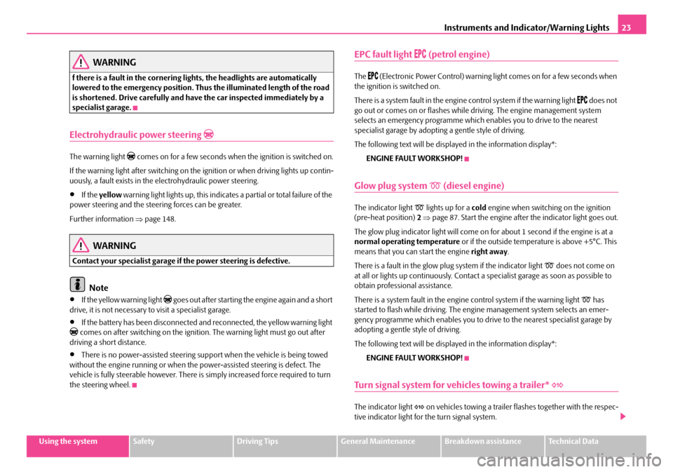
Electrohydraulic power steering
The warning light comes on for a few seconds when the ignition is switched on.
If the warning light after switching on the ig nition or when driving lights up contin- uously, a fault exists in the el ectrohydraulic power steering.
•If the yellow warning light lights up, this indicates a partial or total failure of the power steering and the steering forces can be greater.
Further information ⇒page 148.
WARNING
Contact your specialist garage if the power steering is defective.
Note
•If the yellow warning light goes out after starting the engine again and a short drive, it is not necessary to visit a specialist garage.
•If the battery has been disconnected and reconnected, the yellow warning light comes on after switching on the ignition. The warning light must go out after driving a short distance.
•There is no power-assisted steering support when the vehicle is being towed without the engine running or when the power-assisted steering is defect. The vehicle is fully steerable however. There is simply increased force required to turn the steering wheel.
EPC fault light (petrol engine)
The (Electronic Power Control) warning light comes on for a few seconds when the ignition is switched on.
There is a system fault in the engine control system if the warning light does not go out or comes on or flashes while driving. The engine management system selects an emergency programme which enables you to drive to the nearest specialist garage by adopting a gentle style of driving.
The following text will be displayed in the information display*:
ENGINE FAULT WORKSHOP!
Glow plug system (diesel engine)
The indicator light lights up for a cold engine when switching on the ignition (pre-heat position) 2 ⇒page 87. Start the engine after the indicator light goes out.
The glow plug indicator light will come on for about 1 second if the engine is at a normal operating temperature or if the outside temperature is above +5°C. This means that you can start the engine right away.
There is a fault in the glow plug system if the indicator light does not come on at all or lights up continuously. Contact a specialist garage as soon as possible to obtain professional assistance.
There is a system fault in the engine control system if the warning light has started to flash while driving. The engine management system selects an emer- gency programme which enables you to drive to the nearest specialist garage by adopting a gentle style of driving.
The following text will be displayed in the information display*:
ENGINE FAULT WORKSHOP!
Turn signal system for vehicles towing a trailer*
The indicator light on vehicles towing a trailer flashes together with the respec- tive indicator light for the turn signal system.
NKO A05F 20 MR08.book Page 23 Thursday, April 19, 2007 11:34 AM