lock SKODA FABIA 2007 2.G / 5J Manual PDF
[x] Cancel search | Manufacturer: SKODA, Model Year: 2007, Model line: FABIA, Model: SKODA FABIA 2007 2.G / 5JPages: 242, PDF Size: 48.29 MB
Page 201 of 242

Breakdown assistance200
Jump-starting
Initial steps
You can use the battery of another vehicle for jump-starting yours if the engine does not start because the battery on your vehicle is flat. You will require jump-start cables for this purpose.
Both batteries must have a rated voltage of 12 V. The capacity (Ah) of the battery supplying the power must not be significa ntly less than the capacity of the discharged battery in your vehicle.
Jump-start cables
Only use jump-start cables which have an adequately large cross-section and insu- lated terminal clamps. Plea se pay attention to the manufacturer's instructions.
Positive cable - colour coding in the majority of cases red.
Negative cable - colour coding in the majority of cases black.
WARNING
•A discharged battery may already freeze at temperatures just below 0°C. In case of frozen battery carry out no jump-starting - risk of explosion! Also after thawing of the battery there is a risk of caustic burns due to leaking acid. Replace the frozen battery.
•Please pay attention to the warning in structions relating to working in the engine compartment ⇒page 173.
Note
•There must not be any contact between the two vehicles otherwise current may flow as soon as the negati ve terminals are connected.
•The discharged battery must be properly connected to the system of the vehicle.
•Switch off any installed telephone and also pay attention to the instructions for use of the telephone in such a situation.
•We recommend purchasing jump-start cabl es from Škoda Service Partners as a Škoda original accessory or from retailers who sell branded batteries.
Start engine
It is important to connect the jump-start cables in the correct order.
Connecting positive terminals
– Attach one end to the positive terminal ⇒fig. 165 of the
discharged battery .
– Attach the other end to the positive terminal of the battery
supplying the power .
Connecting negative term inal and engine block
– Attach one end to the negative terminal of the battery supplying
the power .
– Attach the other end to a solid metal part which is connected
firmly to the engine block, or to the engine block itself ⇒.
Fig. 165 Jump-starting using the battery from another vehicle: A - flat vehicle battery, B - battery providing current
A1
AA
A2
AB
A3
AB
A4
NKO A05F 20 MR08.book Page 200 Thursday, April 19, 2007 11:34 AM
Page 202 of 242

Breakdown assistance201
Using the systemSafetyDriving TipsGeneral MaintenanceBreakdown assistanceTechnical Data
Starting engine
– Start the engine of the vehicle providing current and run the engine at
idling speed.
– Now start the engine of the vehicle with the discharged battery.
– Interrupt the attempt at starting an engine after 10 seconds if it does
not start right away and wait for about 30 seconds before repeating
the attempt.
– Disconnect the cables on the engine in exactly the reverse order they
were connected up.
WARNING
•The non-insulated parts of the terminal clamps must never make contact with each other. Furthermore, the cable connected to the positive terminal of the battery must not come into contact with electrically conducting parts of the vehicle - risk of a short circuit!
•Do not affix the jump starting cables to the negative terminal of the discharged battery. There is the risk of detonating gas seeping out the battery being ignited by the strong spark which results from the engine being started.
•Do not affix the cable end to part s of the fuel and brake system.
•Run the jump-start cables so that they cannot be caught by any rotating parts in the engine compartment.
•Do not bend over the batteries - risk of caustic burns!
•The vent screws of the battery cells must be tightened firmly.
•Keep any sources of ignition (naked flame, smouldering cigarettes etc.) away from the battery - risk of an explosion!
Tow-starting and towing vehicle
General
Please pay attention to the following in structions if you are going to use a
tow rope:
Driver of the towing vehicle
– Do not drive off until the tow rope is taught.
– Release the clutch particular ly gently when starting off.
Driver of the towed vehicle
– Switch the ignition on so that th e steering wheel is not blocked and
you can also operate the turn signal lights, the headlight flasher, the
windscreen wipers and windscreen washer system.
– Take the vehicle out of gear or move the selector lever into position N
if your vehicle is fitted with an automatic gearbox.
– Note that the brake servo unit and power steering only operate if the
engine is running. You will require significantly greater physical force
to depress the brake pedal and to steer the vehicle if the engine is not
running.
– Ensure that the tow rope is always kept taught.
Tow rope or tow bar
A tow bar is safest way of towing a vehicle and also minimizes any shocks. You can use a tow rope only if a suitable tow bar is not available.
The tow rope must be elastic to protect the vehicle. Thus one should only use plastic fibre rope or a rope made out of a similarly elastic material.
Attach the tow rope or the tow bar only to the towing eyes provided for this purpose ⇒page 202, “Front towing eye” and ⇒page 203, “Rear towing eye”.
A4
NKO A05F 20 MR08.book Page 201 Thursday, April 19, 2007 11:34 AM
Page 206 of 242

Fuses and light bulbs205
Using the systemSafetyDriving TipsGeneral MaintenanceBreakdown assistanceTechnical Data
Fuses and light bulbs
Electric fuses
Replacing fuses in the dash panel
Defect fuses must be replaced.
Individual electrical circuits are protected by fuses. The fuses are located
on the left side of the dash panel behind the safety cover.
– Switch the ignition off and also the electrical component affected.
– Carefully swivel the cover in the direction of arrow and pull it out
⇒ fig. 169.
– Find out which fuse belongs to the component which is not operating
⇒ page 206, “Fuse assignment in the dash panel”.
– Take the plastic clip out of its fixture in the fuse cover, insert it onto the
respective fuse and pull out this fuse.
– Defect fuses can be detected by their melted metal strips. Replace the
defect fuse by a new fuse of the same ampere number.
– Insert the fuse cover into the dash panel in such a way that the guide
lugs are guided into the openings of the dash panel and then lock
them by pressing.
We recommend that you carry the box of replacement fuses with you which was delivered in your vehicle. You can obtain replacement fuses 7) from a Škoda Service Par tner.
Colour coding of fuses
Caution
•Never attempt to “repair” fuses and also do not replace them with a fuse of a higher amperage - risk of fire! This may also cause damage at another part of the electrical system.
•Have the electrical system checked as quickly as possible by a specialist garage if a newly inserted fuse blows again after a short time.
Fig. 169 Bottom side of the dash panel: fuse cover
7)Replacement fuses are, on the other hand, part of the basic equipping of the vehicle in some countries.
ColourMaximum amperage
light brown5
brown7,5
red10
blue15
yellow20
white25
green30
NKO A05F 20 MR08.book Page 205 Thursday, April 19, 2007 11:34 AM
Page 207 of 242

Fuses and light bulbs206
Note
We recommend that you have these fuses replaced by a specialist garage.
Fuse assignment in the dash panel
Certain electrical components are only st andard on certain vehicle model versions or only suppliable as optional equipment for certain models.
No.Power consumerAmperes
1Electrohydraulic power steering5
2Instrument cluster, headlight range adjustment5
3Engine control unit - Petrol engine5
4ABS control unit5
5Petrol engine: Brake light switch, cruise control system5
6Not assigned
7Engine control unit 1.2 ltr.15
8Injection valves - 1.4 ltr.; 1.6 ltr.10
Fig. 170 Schematic representation of fuse carrier
9Operating controls for the he ating, control unit for air conditioning system, parking aid, control unit for corner- ing lights5
10PCV valve7,5
11Electrically adjustable rear mirror, power windows7,5
12Reversing light10
13Engine control unit (for vehi cles with automatic gearbox)10
14Motor for cornering lights10
15Navigation PDA5
16Not assigned
17Left parking light, licence plate light5
18Right parking light5
19Radio, central control unit5
20Instrument cluster, steering angle sender, ESP, Vehicle voltage control unit5
21Brake lights10
22Operating controls for the he ating, control unit for air conditioning system, parking aid, mobile phone7,5
23Lighting interior, storage compartment and luggage com-partment10
24Tailgate lock10
25Seat heaters20
26Heatable windscreen washing nozzles, windscreen clean- ing system15
27Not assigned
28Petrol engine: AKF valve, petrol engine: Control flap10
29Injection - 1.2 ltr. engine10
No.Power consumerAmperes
NKO A05F 20 MR08.book Page 206 Thursday, April 19, 2007 11:34 AM
Page 209 of 242

Fuses and light bulbs208
Replaces fuses at the battery
– Open the positive terminal cover (+) ⇒fig. 171.
– Press onto the interlocks of the fuse covers ⇒fig. 172 and open
the covers.
– Press together the interlocks of th e fuse cover simultaneously and
push out the cover in the direction of the arrow.
– Find out which fuse belongs to the component which is not operating
⇒ page 208, “Fuse assignment at battery”.
– Defect fuses can be detected by th eir melted metal strips. Replace the
defect fuse by a new fuse of the same ampere number.
Caution
•Never attempt to “repair” fuses and also do not replace them with a fuse of a higher amperage - risk of fire! This may also cause damage at another part of the electrical system.
•Have the electrical system checked as quickly as possible by a specialist garage if a newly inserted fuse blows again after a short time.
Note
•We recommend that you have these fuse s replaced by a specialist garage.
•Some vehicles are only fitted with the cover ⇒fig. 172.
Fuse assignment at battery
Certain electrical components are only standard on certain vehicle model versions or only suppliable as optional equipment for certain models.
Fig. 171 The battery: Opening of the positive terminal cover.
Fig. 172 The battery: fuse cover
AA
AB
AB
Fig. 173 Schematic representation of fuse assignment at battery
NKO A05F 20 MR08.book Page 208 Thursday, April 19, 2007 11:34 AM
Page 212 of 242

Fuses and light bulbs211
Using the systemSafetyDriving TipsGeneral MaintenanceBreakdown assistanceTechnical Data
Switching on the low beam and main beam
– Open the bonnet.
– Remove the protective cap ⇒page 210, fig. 174.
– For headlights with module (halogen lamp H7) ⇒fig. 176 turn the
connector with the halogen lamp to the left up to the stop and
remove.
– For headlights with reflector (halogen lamp H4) pull off the connector
from the lamp, release the sprung wi re clamp and pull out the halogen
lamp towards the rear.
– Replace the halogen lamp H7, insert the connector with the new
halogen lamp and turn to the right up to the stop.
– Replace the halogen lamp H4, insert into the opening in the reflector
(with the fixing lugs in the recesses), secure with the sprung wire
clamp, position the protective cap and mount the connector.
– We recommend that you have the headlight setting checked by a
Skoda Service Partner after replacing the light bulb.
Turn signal light (at the front)
– Open the bonnet.
– Turn the lamp holder to the left ⇒page 210, fig. 174 and remove
the lamp holder with the light bulb.
– Replace the defective light bulb.
– Insert the lamp holder with light bulb into the headlight. Secure the
lamp holder by turning it to the right until it locks in place.
Parking light at the front
– Open the bonnet.
– Remove the protective cap ⇒page 210, fig. 174.
– Grasp the light bulb holder an d pull it out of the headlight.
– Replace the light bulb in the light bulb holder and re-insert into the
headlight.
Fog lights
Fig. 176 Removing the light bulb for the low beam and main beam light
AA
AC
AB
Fig. 177 Structure of the light bulb of the fog light
NKO A05F 20 MR08.book Page 211 Thursday, April 19, 2007 11:34 AM
Page 217 of 242

Technical Data216
Vehicle data sticker
The vehicle data sticker ⇒page 215, fig. 185 is located on the floor of the luggage compartment and is also stated in the Service schedule.
The vehicle data sticker co ntains the following data:
Vehicle identification number (VIN)
Vehicle type
Gearbox code, paint number, interior equipment number, engine output, engine code
Partial description of the vehicle
7GG - vehicles with DPF ⇒page 150
Vehicle identification number (VIN)
The vehicle identification num ber - VIN (vehicle body number) is stamped into the engine compartment on the right hand shoc k absorber dome. This number is also located on a sign on the lower left hand edge below the windscreen (together with a VIN bar code).
Engine number
The engine number is stamped into the engine block.
Type plate (production plate)
The type plate is located in the engine co mpartment at the front on the left hand shock absorber dome.
Homologation sign
The homologation sign is located on the lo ck carrier. Vehicles for certain countries do not have an homologation sign.
Sticker on inside of fuel filler flap
The sticker is affixed to the inside of the fuel filler flap. The sticker contains the following data:
•The prescribed types of fuel,
•Tyre si z e,
•Tyre pressure.
Fuel consumption according to the regulations
(99/100/EU)
Depending on the range of the special equipment, style of driving, traffic situation, weather influences and vehi cle condition, the consumption values which in prac- tice result when using the vehicle ca n deviate from the indicated values.
Urban traffic
The consumption measurement in urban traf fic begins with starting of the cold engine. Afterwards the normal urban traffic is simulated.
Non-urban traffic
For the consumption measurement in non-ur ban traffic the vehicle, as in daily motoring, is accelerated and braked several times in all gears. The vehicle speed changes within the range from 0 to 120 km/h.
Combined traffic
The consumption value in the combined traf fic consists of 37% from the value for the urban traffic and of 63% from the value for the non-urban traffic.
Note
•Please note that the information stated in the official vehicle registration documents always takes priority.
A1
A2
A3
A4
A5
NKO A05F 20 MR08.book Page 216 Thursday, April 19, 2007 11:34 AM
Page 234 of 242
Index233
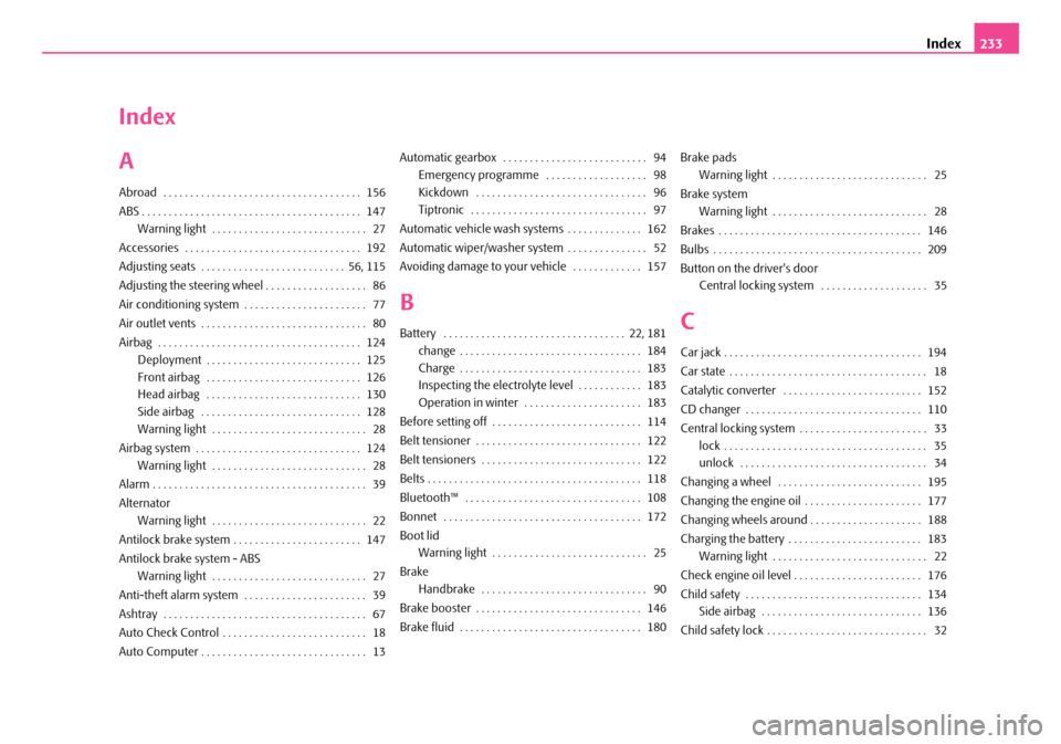
Index
A
Abroad . . . . . . . . . . . . . . . . . . . . . . . . . . . . . . . . . . . . . 156
ABS . . . . . . . . . . . . . . . . . . . . . . . . . . . . . . . . . . . . . . . . . 147
Warning light . . . . . . . . . . . . . . . . . . . . . . . . . . . . . 27
Accessories . . . . . . . . . . . . . . . . . . . . . . . . . . . . . . . . . 192
Adjusting seats . . . . . . . . . . . . . . . . . . . . . . . . . . . 56, 115
Adjusting the steering wheel . . . . . . . . . . . . . . . . . . . 86
Air conditioning system . . . . . . . . . . . . . . . . . . . . . . . 77
Air outlet vents . . . . . . . . . . . . . . . . . . . . . . . . . . . . . . . 80
Airbag . . . . . . . . . . . . . . . . . . . . . . . . . . . . . . . . . . . . . . 124
Deployment . . . . . . . . . . . . . . . . . . . . . . . . . . . . . 125
Front airbag . . . . . . . . . . . . . . . . . . . . . . . . . . . . . 126
Head airbag . . . . . . . . . . . . . . . . . . . . . . . . . . . . . 130
Side airbag . . . . . . . . . . . . . . . . . . . . . . . . . . . . . . 128
Warning light . . . . . . . . . . . . . . . . . . . . . . . . . . . . . 28
Airbag system . . . . . . . . . . . . . . . . . . . . . . . . . . . . . . . 124
Warning light . . . . . . . . . . . . . . . . . . . . . . . . . . . . . 28
Alarm . . . . . . . . . . . . . . . . . . . . . . . . . . . . . . . . . . . . . . . . 39
Alternator
Warning light . . . . . . . . . . . . . . . . . . . . . . . . . . . . . 22
Antilock brake system . . . . . . . . . . . . . . . . . . . . . . . . 147
Antilock brake system - ABS
Warning light . . . . . . . . . . . . . . . . . . . . . . . . . . . . . 27
Anti-theft alarm system . . . . . . . . . . . . . . . . . . . . . . . 39
Ashtray . . . . . . . . . . . . . . . . . . . . . . . . . . . . . . . . . . . . . . 67
Auto Check Control . . . . . . . . . . . . . . . . . . . . . . . . . . . 18
Auto Computer . . . . . . . . . . . . . . . . . . . . . . . . . . . . . . . 13
Automatic gearbox . . . . . . . . . . . . . . . . . . . . . . . . . . . 94
Emergency programme . . . . . . . . . . . . . . . . . . . 98
Kickdown . . . . . . . . . . . . . . . . . . . . . . . . . . . . . . . . 96
Tiptronic . . . . . . . . . . . . . . . . . . . . . . . . . . . . . . . . . 97
Automatic vehicle wash systems . . . . . . . . . . . . . . 162
Automatic wiper/washer system . . . . . . . . . . . . . . . 52
Avoiding damage to your vehicle . . . . . . . . . . . . . 157
B
Battery . . . . . . . . . . . . . . . . . . . . . . . . . . . . . . . . . . 22, 181
change . . . . . . . . . . . . . . . . . . . . . . . . . . . . . . . . . . 184
Charge . . . . . . . . . . . . . . . . . . . . . . . . . . . . . . . . . . 183
Inspecting the electrolyte level . . . . . . . . . . . . 183
Operation in winter . . . . . . . . . . . . . . . . . . . . . . 183
Before setting off . . . . . . . . . . . . . . . . . . . . . . . . . . . . 114
Belt tensioner . . . . . . . . . . . . . . . . . . . . . . . . . . . . . . . 122
Belt tensioners . . . . . . . . . . . . . . . . . . . . . . . . . . . . . . 122
Belts . . . . . . . . . . . . . . . . . . . . . . . . . . . . . . . . . . . . . . . . 118
Bluetooth™ . . . . . . . . . . . . . . . . . . . . . . . . . . . . . . . . . 108
Bonnet . . . . . . . . . . . . . . . . . . . . . . . . . . . . . . . . . . . . . 172
Boot lid
Warning light . . . . . . . . . . . . . . . . . . . . . . . . . . . . . 25
Brake
Handbrake . . . . . . . . . . . . . . . . . . . . . . . . . . . . . . . 90
Brake booster . . . . . . . . . . . . . . . . . . . . . . . . . . . . . . . 146
Brake fluid . . . . . . . . . . . . . . . . . . . . . . . . . . . . . . . . . . 180
Brake pads
Warning light . . . . . . . . . . . . . . . . . . . . . . . . . . . . . 25
Brake system
Warning light . . . . . . . . . . . . . . . . . . . . . . . . . . . . . 28
Brakes . . . . . . . . . . . . . . . . . . . . . . . . . . . . . . . . . . . . . . 146
Bulbs . . . . . . . . . . . . . . . . . . . . . . . . . . . . . . . . . . . . . . . 209
Button on the driver's door
Central locking system . . . . . . . . . . . . . . . . . . . . 35
C
Car jack . . . . . . . . . . . . . . . . . . . . . . . . . . . . . . . . . . . . . 194
Car state . . . . . . . . . . . . . . . . . . . . . . . . . . . . . . . . . . . . . 18
Catalytic converter . . . . . . . . . . . . . . . . . . . . . . . . . . 152
CD changer . . . . . . . . . . . . . . . . . . . . . . . . . . . . . . . . . 110
Central locking system . . . . . . . . . . . . . . . . . . . . . . . . 33
lock . . . . . . . . . . . . . . . . . . . . . . . . . . . . . . . . . . . . . . 35
unlock . . . . . . . . . . . . . . . . . . . . . . . . . . . . . . . . . . . 34
Changing a wheel . . . . . . . . . . . . . . . . . . . . . . . . . . . 195
Changing the engine oil . . . . . . . . . . . . . . . . . . . . . . 177
Changing wheels around . . . . . . . . . . . . . . . . . . . . . 188
Charging the battery . . . . . . . . . . . . . . . . . . . . . . . . . 183
Warning light . . . . . . . . . . . . . . . . . . . . . . . . . . . . . 22
Check engine oil level . . . . . . . . . . . . . . . . . . . . . . . . 176
Child safety . . . . . . . . . . . . . . . . . . . . . . . . . . . . . . . . . 134
Side airbag . . . . . . . . . . . . . . . . . . . . . . . . . . . . . . 136
Child safety lock . . . . . . . . . . . . . . . . . . . . . . . . . . . . . . 32
NKO A05F 20 MR08.book Page 233 Thursday, April 19, 2007 11:34 AM
Page 235 of 242

Index234
Child safety seat
on the front passenger seat . . . . . . . . . . . . . . . 135
Safety information . . . . . . . . . . . . . . . . . . . . . . . 134
Child seat . . . . . . . . . . . . . . . . . . . . . . . . . . . . . . . . . . . 137
Classification into groups . . . . . . . . . . . . . . . . . 137
ISOFIX system . . . . . . . . . . . . . . . . . . . . . . . . . . . . 140
Children and safety . . . . . . . . . . . . . . . . . . . . . . . . . . 134
Chrome parts . . . . . . . . . . . . . . . . . . . . . . . . . . . . . . . 163
Cigarette lighter . . . . . . . . . . . . . . . . . . . . . . . . . . . . . . 67
Cleaning . . . . . . . . . . . . . . . . . . . . . . . . . . . . . . . . . . . . 161
Climatronic
Air outlet vents . . . . . . . . . . . . . . . . . . . . . . . . . . . . 85
Defrosting windows . . . . . . . . . . . . . . . . . . . . . . . 84
Recirculated air mode . . . . . . . . . . . . . . . . . . . . . 84
Setting temperature . . . . . . . . . . . . . . . . . . . . . . . 84
Clock . . . . . . . . . . . . . . . . . . . . . . . . . . . . . . . . . . . . . . . . 13
Clothes hooks . . . . . . . . . . . . . . . . . . . . . . . . . . . . . . . . 73
Cockpit
General view . . . . . . . . . . . . . . . . . . . . . . . . . . . . . . . 8
Compartments . . . . . . . . . . . . . . . . . . . . . . . . . . . . . . . 68
Computer . . . . . . . . . . . . . . . . . . . . . . . . . . . . . . . . . . . . 13
Convenience operation . . . . . . . . . . . . . . . . . . . . . . . 42
Converting/masking over headlights . . . . . . . . . . 156
Coolant . . . . . . . . . . . . . . . . . . . . . . . . . . . . . . . . . . . . . 177
replenishing . . . . . . . . . . . . . . . . . . . . . . . . . . . . . 179
Warning light . . . . . . . . . . . . . . . . . . . . . . . . . . . . . 24
Coolant level
Warning light . . . . . . . . . . . . . . . . . . . . . . . . . . . . . 24
Coolant temperature gauge . . . . . . . . . . . . . . . . . . . 10
Coolant temperature/coolant level
Warning light . . . . . . . . . . . . . . . . . . . . . . . . . . . . . 24
Cornering lights . . . . . . . . . . . . . . . . . . . . . . . . . . . . . . . 46
Warning light . . . . . . . . . . . . . . . . . . . . . . . . . . . . . . 22
Correct seated position . . . . . . . . . . . . . . . . . . . . . . 115
Counter for distance driven . . . . . . . . . . . . . . . . . . . . 11
Cruise control system . . . . . . . . . . . . . . . . . . . . . . . . . . 91
Cup holder
front . . . . . . . . . . . . . . . . . . . . . . . . . . . . . . . . . . . . . . 65
rear . . . . . . . . . . . . . . . . . . . . . . . . . . . . . . . . . . . . . . . 66
D
Deactivating an airbag . . . . . . . . . . . . . . . . . . . . . . . 131
Defrosting rear window . . . . . . . . . . . . . . . . . . . . . . . . 51
Defrosting windows . . . . . . . . . . . . . . . . . . . . . . . 76, 79
De-icing the windows . . . . . . . . . . . . . . . . . . . . . . . 164
Diesel . . . . . . . . . . . . . . . . . . . . . . . . . . . . . . . . . . . . . . 169
Diesel engines
Starting the engine . . . . . . . . . . . . . . . . . . . . . . . . . 88
Diesel particle filter . . . . . . . . . . . . . . . . . . . . . . . . . . 150
Warning light . . . . . . . . . . . . . . . . . . . . . . . . . . . . . . 29
Digital clock . . . . . . . . . . . . . . . . . . . . . . . . . . . . . . . . . . 13
Direction indicators . . . . . . . . . . . . . . . . . . . . . . . . . . . 48
Warning light . . . . . . . . . . . . . . . . . . . . . . . . . . . . . . 22
Display . . . . . . . . . . . . . . . . . . . . . . . . . . . . . . . . . . . . . . . 16
Distance driven . . . . . . . . . . . . . . . . . . . . . . . . . . . . . . . 11
Door
Child safety lock . . . . . . . . . . . . . . . . . . . . . . . . . . . 32
Warning light . . . . . . . . . . . . . . . . . . . . . . . . . . . . . . 25
Door, luggage compartment door and bonnet ajar warning . . . . . . . . . . . . . . . . . . . . . . . . . . . . . . . . . 18
Driving economically . . . . . . . . . . . . . . . . . . . . . . . . 152
Driving time . . . . . . . . . . . . . . . . . . . . . . . . . . . . . . . . . . 16
E
EDL . . . . . . . . . . . . . . . . . . . . . . . . . . . . . . . . . . . . . . . . . 145
Electric power-operated window
Operational faults . . . . . . . . . . . . . . . . . . . . . . . . . 42
Electric sliding/tilting roof . . . . . . . . . . . . . . . . . . . . . 43
Electrically adjustable rear mirror . . . . . . . . . . . . . . 54
Electronic Differential Lock . . . . . . . . . . . . . . . . . . . 145
Warning light . . . . . . . . . . . . . . . . . . . . . . . . . . . . . 27
Electronic Differential Lock (EDL) . . . . . . . . . . . . . 145
Electronic immobiliser . . . . . . . . . . . . . . . . . . . . . 24, 31
Warning light . . . . . . . . . . . . . . . . . . . . . . . . . . . . . 24
Electronic stability programme (ESP) . . . . . . . . . . 143
Warning light . . . . . . . . . . . . . . . . . . . . . . . . . . . . . 27
Emergency locking of the door . . . . . . . . . . . . . . . . . 36
Engine
starting . . . . . . . . . . . . . . . . . . . . . . . . . . . . . . . . . . . 87
switching off . . . . . . . . . . . . . . . . . . . . . . . . . . . . . . 89
Engine compartment
Safety information . . . . . . . . . . . . . . . . . . . . . . . . 173
Engine electronics
Warning light . . . . . . . . . . . . . . . . . . . . . . . . . . . . . 23
Engine oil . . . . . . . . . . . . . . . . . . . . . . . . . . . . . . . . . . . 175
change . . . . . . . . . . . . . . . . . . . . . . . . . . . . . . . . . . 177
check . . . . . . . . . . . . . . . . . . . . . . . . . . . . . . . . . . . . 176
replenishing . . . . . . . . . . . . . . . . . . . . . . . . . . . . . 177
Warning light . . . . . . . . . . . . . . . . . . . . . . . . . . . . . 25
Engine revolutions counter . . . . . . . . . . . . . . . . . . . . . 9
Environment . . . . . . . . . . . . . . . . . . . . . . . . . . . . . . . . 152
Environmental compatibility . . . . . . . . . . . . . 152, 155
ESP . . . . . . . . . . . . . . . . . . . . . . . . . . . . . . . . . . . . . . . . . 143
Warning light . . . . . . . . . . . . . . . . . . . . . . . . . . . . . 27
NKO A05F 20 MR08.book Page 234 Thursday, April 19, 2007 11:34 AM
Page 236 of 242

Index235
Exhaust gas
Warning light . . . . . . . . . . . . . . . . . . . . . . . . . . . . . . 26
Exhaust gas inspection
Warning light . . . . . . . . . . . . . . . . . . . . . . . . . . . . . . 26
Explanations . . . . . . . . . . . . . . . . . . . . . . . . . . . . . . . . . . . 6
Exterior mirror . . . . . . . . . . . . . . . . . . . . . . . . . . . . . . . . 54
Exterior mirror heater . . . . . . . . . . . . . . . . . . . . . . . . . . 54
F
Fastening elements . . . . . . . . . . . . . . . . . . . . . . . . . . . . 62
First-aid box . . . . . . . . . . . . . . . . . . . . . . . . . . . . . . . . 193
Fog lights . . . . . . . . . . . . . . . . . . . . . . . . . . . . . . . . 46, 211
Warning light . . . . . . . . . . . . . . . . . . . . . . . . . . . . . . 22
Fog lights with integrated turning light . . . . . . . . . . 47
Force limiter of the power windows . . . . . . . . . . . . 41
Front airbag . . . . . . . . . . . . . . . . . . . . . . . . . . . . . . . . . 126
Front armrest . . . . . . . . . . . . . . . . . . . . . . . . . . . . . . . . . 71
Front headlight . . . . . . . . . . . . . . . . . . . . . . . . . . . . . . 210
Fuel . . . . . . . . . . . . . . . . . . . . . . . . . . . . . . . . . . . . . . . . 169
Diesel fuel . . . . . . . . . . . . . . . . . . . . . . . . . . . . . . . 169
Fuel gauge . . . . . . . . . . . . . . . . . . . . . . . . . . . . . . . . 10
Petrol . . . . . . . . . . . . . . . . . . . . . . . . . . . . . . . . . . . 169
Warning light . . . . . . . . . . . . . . . . . . . . . . . . . . . . . . 24
Fuel consumption . . . . . . . . . . . . . . . . . . . . . . . . 15, 152
Saving energy . . . . . . . . . . . . . . . . . . . . . . . . . . . 152
Fuel gauge . . . . . . . . . . . . . . . . . . . . . . . . . . . . . . . . . . . . 10
Fuel reserve
Warning light . . . . . . . . . . . . . . . . . . . . . . . . . . . . . . 24
Full wheel trim . . . . . . . . . . . . . . . . . . . . . . . . . . . . . . 196
Fuse
Assignment . . . . . . . . . . . . . . . . . . . . . . . . . . . . . 206
Fuses . . . . . . . . . . . . . . . . . . . . . . . . . . . . . . . . . . . . . . . 205
G
Gauges . . . . . . . . . . . . . . . . . . . . . . . . . . . . . . . . . . . . . . . . 9
Gearbox
mechanical . . . . . . . . . . . . . . . . . . . . . . . . . . . . . . . 89
General view
Cockpit . . . . . . . . . . . . . . . . . . . . . . . . . . . . . . . . . . . . 8
Glass roof . . . . . . . . . . . . . . . . . . . . . . . . . . . . . . . . . . . . 43
Glow plug system . . . . . . . . . . . . . . . . . . . . . . . . . . . . . 88
Warning light . . . . . . . . . . . . . . . . . . . . . . . . . . . . . . 23
H
Handbrake . . . . . . . . . . . . . . . . . . . . . . . . . . . . . . . . . . . 90
Hazard warning light system . . . . . . . . . . . . . . . . . . . 48
Warning light . . . . . . . . . . . . . . . . . . . . . . . . . . . . . . 22
Head airbag . . . . . . . . . . . . . . . . . . . . . . . . . . . . . . . . . 130
Head restraint . . . . . . . . . . . . . . . . . . . . . . . . . . . . . . . . 57
Headlight cleaning system . . . . . . . . . . . . . . . . . . . . . 53
Headlight flasher . . . . . . . . . . . . . . . . . . . . . . . . . . . . . . 49
Headlights
Fog lights . . . . . . . . . . . . . . . . . . . . . . . . . . . . . . . . . 46
Headlight cleaning system . . . . . . . . . . . . . . . . . 53
Heated windscreen washer nozzles . . . . . . . . . . . . 52
Heating . . . . . . . . . . . . . . . . . . . . . . . . . . . . . . . . . . . . . . 75
Heating the front seats . . . . . . . . . . . . . . . . . . . . . . . . 58
Horn . . . . . . . . . . . . . . . . . . . . . . . . . . . . . . . . . . . . . . . . . . 8
I
Ignition . . . . . . . . . . . . . . . . . . . . . . . . . . . . . . . . . . . . . . 87
Ignition lock . . . . . . . . . . . . . . . . . . . . . . . . . . . . . . . . . . 87
Immobiliser . . . . . . . . . . . . . . . . . . . . . . . . . . . . . . . . . . 31
Warning light . . . . . . . . . . . . . . . . . . . . . . . . . . . . . 24
Information display . . . . . . . . . . . . . . . . . . . . . . . . . . . 16
Instrument cluster . . . . . . . . . . . . . . . . . . . . . . . . . . . . . . 9
Interior light
Luggage compartment . . . . . . . . . . . . . . . . . . . . 50
Interior lighting
front . . . . . . . . . . . . . . . . . . . . . . . . . . . . . . . . . . . . . 49
rear . . . . . . . . . . . . . . . . . . . . . . . . . . . . . . . . . . . . . . 50
Interior monitor . . . . . . . . . . . . . . . . . . . . . . . . . . . . . . 40
Intermittent wiping . . . . . . . . . . . . . . . . . . . . . . . . . . . 52
ISOFIX . . . . . . . . . . . . . . . . . . . . . . . . . . . . . . . . . . . . . . 140
ISOFIX system . . . . . . . . . . . . . . . . . . . . . . . . . . . . . . . 140
J
Jacking points . . . . . . . . . . . . . . . . . . . . . . . . . . . . . . . 198
Jump-starting . . . . . . . . . . . . . . . . . . . . . . . . . . . . . . . 200
K
Key . . . . . . . . . . . . . . . . . . . . . . . . . . . . . . . . . . . . . . . . . . 30
L
Lashing eyes . . . . . . . . . . . . . . . . . . . . . . . . . . . . . . . . . 62
Leather care . . . . . . . . . . . . . . . . . . . . . . . . . . . . . . . . 166
Lighting
Interior light and reading light . . . . . . . . . . . . . 212
Storage compartment lighting . . . . . . . . . . . . . 212
Lighting of the interior of the vehicle
front . . . . . . . . . . . . . . . . . . . . . . . . . . . . . . . . . . . . . 49
NKO A05F 20 MR08.book Page 235 Thursday, April 19, 2007 11:34 AM