lock SKODA FABIA 2007 2.G / 5J Repair Manual
[x] Cancel search | Manufacturer: SKODA, Model Year: 2007, Model line: FABIA, Model: SKODA FABIA 2007 2.G / 5JPages: 242, PDF Size: 48.29 MB
Page 172 of 242

Fuel171
Using the systemSafetyDriving TipsGeneral MaintenanceBreakdown assistanceTechnical Data
– Lock the fuel filler cap on the fuel filler tube to the right using the
vehicle key.
– Press the fuel tank flap closed.
The correct grades of fuel for your vehicle are stated on a sticker affixed to the inside of the fuel filler flap. Further information on fuel ⇒page 169.
The fuel tank has a capacity of about 45 litres.
WARNING
Pay attention to any legal requirements if you do carry a spare canister in the vehicle. We do not recommend carrying any fuel canisters in your vehicle for safety reasons. The canister can be da maged in the event of an accident and fuel may leak out.
Caution
•Remove any fuel which has spilled onto the paintwork of your vehicle immedi- ately - risk of paint damage!
•Vehicles fitted with catalytic converter sh ould never be allowed to let the fuel tank to run completely empty. An irregular supply of fuel to the engine can result in misfiring and unburnt fuel may get into the exhaust system, which may result in overheating and damage to the catalytic converter.
•Make sure that the valve is not pressed into the filler tube when inserting the pump nozzle into the filler tube. Otherwis e you are unintentionally filling up the volume, which in case of heat can cause an expansion of the fuel. This can lead to an overflow of fuel or damage to parts of the fuel reservoir.
•T h e f u e l t a n k i s f u l l j u s t a s s o o n a s t he pump nozzle switches off for the first time, provided the nozzle has been operated properly. Do not continue refuelling - otherwise the expansion volume is filled up.
NKO A05F 20 MR08.book Page 171 Thursday, April 19, 2007 11:34 AM
Page 173 of 242

Inspecting and Replenishing172
Inspecting and Replenishing
Engine compartment
Bonnet remote release
Bonnet remote release
– Pull the unlocking lever on the left below the dash panel ⇒fig. 144.
The bonnet jumps out of its lock as a result of the spring force.
Opening and closing the bonnet
Opening the bonnet
– Unlock the bonnet ⇒fig. 144.
– Ensure that the arms of the windsc reen wipers are correctly in place
against the windscreen before opening the bonnet otherwise
damage could occur to the paintwork.
– Press the locking button ⇒fig. 145, the bonnet unlocks itself.
Fig. 144 Bonnet release lever
Fig. 145 Radiator grille: Fuse
Fig. 146 Securing the bonnet with the bonnet support
NKO A05F 20 MR08.book Page 172 Thursday, April 19, 2007 11:34 AM
Page 174 of 242

Inspecting and Replenishing173
Using the systemSafetyDriving TipsGeneral MaintenanceBreakdown assistanceTechnical Data
– Grip the bonnet and lift it up.
– Take the bonnet support out of its holder and set it in the opening
designed for it ⇒page 172, fig. 146.
Closing the bonnet
– Lift the bonnet slightly and unhook the bonnet support. Press the
bonnet support into the hold er designed to hold it.
– Allow the bonnet to drop from a height of about 30 cm into the lock -
bonnet do not press down on it!
WARNING
•Never open the bonnet if you see that steam or coolant is flowing out of the engine compartment - risk of scaldi ng! Wait long enough until the steam or coolant has stopped escaping.
•For safety reasons, the bonnet must always be properly closed when driving. One should therefore check that the lock has in fact engaged prop- erly after closing the bonnet.
•Stop your vehicle immediately while driv ing if you notice that the lock is not properly engaged and close the bonne t properly - risk of an accident!
Caution
•Before opening the bonnet, ensure that the arms of the windscreen wipers are correctly in place against the windscreen. Otherwise, there is a risk of damage to the paintwork.
Working in the engine compartment
Particular care is required when carrying out any work in the engine
compartment!
There is a risk of injuries, scalding, accidents and fire when working in the engine compartment, e.g. inspecting and replenishing oil and other fluids. For
this reason, it is essential to comply with the warning instructions stated below and with the general applicable rules of safety. The engine compart- ment of your car is a hazardous area ⇒.
WARNING
•Never open the bonnet if you see that steam or coolant is flowing out of the engine compartment - risk of scaldi ng! Wait long enough until the steam or coolant has stopped escaping.
•Switch off the engine and pull out the ignition key.
•Apply the handbrake firmly.
•If your vehicle is fitted with a ma nual gearbox, move the gearshift lever into Neutral, or if it is fitted with automatic gearbox, move the selector lever into position P.
•Allow the engine to cool down.
•Keep children clear of the engine compartment.
•Do not touch any hot engine parts - risk of burns!
•Never spill oil and other fluids over the hot engine. Such fluids (e.g. the antifreeze contained in the coolant) may ignite!
•Avoid short circuits in the electrical system - particularly on the battery.
•Never place your hand into the radiator fan as long as the engine is still warm. The fan might suddenly start running!
•Never open the cap of the coolant expa nsion bottle as long as the engine is still warm. The cooling system is pressurized!
•Cover over the cap of the coolant expansion reservoir with a large cloth when opening it as protection for your face, hands and arms from hot steam or hot coolant.
•Do not let objects, such as e.g cleaning cloth or tools lie in the engine compartment.
•If you wish to work under the vehicle, you must secure the vehicle from rolling away and support it with suitable supporting blocks: the car jack is not sufficient for this - risk of injury!
•In cases where it be necessary to carry out inspection work when the engine is running there is an additional risk from rotating parts (e.g. the V-
NKO A05F 20 MR08.book Page 173 Thursday, April 19, 2007 11:34 AM
Page 180 of 242

Inspecting and Replenishing179
Using the systemSafetyDriving TipsGeneral MaintenanceBreakdown assistanceTechnical Data
Losses can only occur through the pressure relief in the cap of the coolant expan- sion bottle which is completely free of leak s if the coolant boils as a result of over- heating and is forced out of the cooling system.
WARNING
Read and observe the warning notes ⇒page 173, “Working in the engine compartment” before working in the engine compartment.
Caution
One should contact a specialist garage as soon as possible if the source of over-heating itself cannot be determined and removed, since there may be grave damage to the engine.
Replenishing the coolant
– Switch the engine off.
– Allow the engine to cool down.
– Place a cloth over the cap of the coolant expansion reservoir
⇒ page 178, fig. 149 and unscrew the cap carefully by turning it to the
left ⇒.
– Top up the coolant.
– Screw the cap tight until it is heard to lock.
The coolant which you use for replenishi ng the system, must comply with one specific specification ⇒page 177, “Coolant”. Do not use an alternative additive if the coolant additive G12 PLUS is not available in exceptional cases. Just top up the system with water and as soon as possible arrange adjustment to correct the mixing ratio of water and coolant additive again by a specialist garage.
Only use fresh coolant for topping up the system.
Do not fill up over the “MAX” marking! Ex cess coolant which is heated up is forced out of the cooling system through the pressu re relief valve in the cap of the coolant compensation bottle.
Wait until the engine has cooled down for a system which has suffered a major loss of coolant before pouring in coolant. Th is is necessary to avoid engine damage.
WARNING
•The cooling system is pressurized! Do not open the cap of the coolant expansion bottle if the engine is still hot - risk of scalding!
•The coolant additive and thus all of the coolant is harmful to your health. Avoid contact with the coolant. Coolant vapours are also harmful to the health. It is important, therefore, to always safely store any coolant additive in its original container out of the reach of children - risk of poisoning!
•If any splashes of coolant get into yo ur eyes, rinse out your eyes immedi- ately with clear water and contac t a doctor as soon as possible.
•You should also consult a doctor without delay if you have inadvertently swallowed coolant.
Caution
Do not continue your journey if for some reason it is not possible under the conditions prevailing to top up with coolant. Switch the engine off and obtain professional assistance from a specialist garage, otherwise it could lead to severe engine damage.
For the sake of the environment
Do not re-use coolant if it is necessary to drain the coolant in the system. It should be collected and disposed of in comp liance with environmental protection regulations.
NKO A05F 20 MR08.book Page 179 Thursday, April 19, 2007 11:34 AM
Page 182 of 242

Inspecting and Replenishing181
Using the systemSafetyDriving TipsGeneral MaintenanceBreakdown assistanceTechnical Data
One may only use new genuine brake fluid from Škoda Auto a.s. The specification for the brake fluid is “FMVSS 116 DOT 4”.
We recommend that you have the brake fluid replaced by a Škoda Service Partner as part of an Inspection Service.
WARNING
•Using old brake fluid can result in seve re stress on the brakes because of the formation of vapour bubbles in th e brake system. This greatly impairs the braking efficiency and thus al so the safety of your vehicle.
•Brake fluid is toxic! It must therefore be kept safely in closed original containers and well away from children and unauthorized persons.
Caution
Brake fluid damages the paintwork of the vehicle.
For the sake of the environment
In view of the problems involved with prop er disposal of brake fluid, the special tools and the professional knowledge required, we recommend you have the brake fluid replaced by a Škoda Service Partner.
Battery
Working on the battery
The battery is located in the engi ne compartment below a plastic box.
– Unlock the interlock on the positive terminal side of the battery
⇒ fig. 151.
– Open the cover in direction of arrow.
– The installation of the battery cover on the positive terminal side takes
place in the reverse order.
Removal and installation of the battery is not recommended since it can, under certain circumstances, lead to major damage to the battery and fuse boxes. Contact a specialist garage.
There is a risk of injuries, scalding, acci dents and burns when carrying out any work on the battery and on the electrical system. For this reason, it is essential to comply with the warning instructions ⇒ stated below and with the general applicable rules of safety.
Fig. 151 The battery: Open up the cover
NKO A05F 20 MR08.book Page 181 Thursday, April 19, 2007 11:34 AM
Page 192 of 242

Wheels and Tyres191
Using the systemSafetyDriving TipsGeneral MaintenanceBreakdown assistanceTechnical Data
Only use fine-link snow chains. They must not project more than 9 mm - including the chain lock.
Remove the full wheel trims before installing the snow chains.
Observe the national legal requirements rela ting to the use of snow chains and the maximum vehicle speed with snow chains.
WARNING
Please pay attention to the information in the supplied fitting instructions of the snow chain manufacturer.
Caution
You must take the chains off as soon as you drive on roads which are free of snow. They adversely affect the hand ling of your vehicle, damage the tyres and are rapidly destroyed.
Note
•Only fit snow chains from the ra nge of Škoda genuine accessories.
•When driving with snow chains, switch off the traction control system (TCS).
NKO A05F 20 MR08.book Page 191 Thursday, April 19, 2007 11:34 AM
Page 195 of 242

Breakdown assistance194
Vehicle tool kit
The vehicle tool kit and the lifting jack are stored in a locable plastic box in the spare wheel ⇒fig. 157. There is also space here for the removable ball for the trailer towing device.
The vehicle tool kit contains the following parts (depending on equipment fitted):
•Torx wrench,
•Wheel wrench,
•Hook for pulling off a full wheel trim,
•Towing eye,
•Adapter for the wheel bolts lock.
After using the lifting jack, screw in the arm of the lifting jack fully before placing it back in its stowage area.
WARNING
•The factory-supplied lifting jack is only intended for your model of vehicle. On no account attempt to lift a heavier vehicle or other loads - risk of injury!
•Ensure that the vehicle tool kit is safely attached in the luggage compartment.
Tyre repair kit*
The tyre repair kit is intended for the repair of minor tyre defects. The tyre repair kit contains a compressor, inflation bottle, operating instructions and accessories.
The repair with the tyre repair kit is not at all intended to replace a permanent re pair on the tyre, this repai r only s er v es to reach the next w orks hop. T he re pa ir can be undertaken on the vehicle immediately. Please read the attached instructions carefully before the repair.
The tyre repair kit is locate d in the luggage compartment.
Spare wheel*
The spare wheel is stowed in the spare wheel well in the luggage
compartment below the floor covering.
The spare wheel lies in a well under the luggage compartment floor and is fixed in place along with the vehicle tool kit box using special screws ⇒fig. 158.
One should check the inflation pressure in the spare wheel (at best when generally checking the tyre air pressures - see sign on the fuel filler flap ⇒page 170) to ensure that the spare wheel is always ready to use.
Unidirectional tyres*
If you have such tyres on your vehicle, please refer to the notes below:
Fig. 157 Luggage compartment: Storage compartment for vehicle too kit
Fig. 158 Luggage compartment: Spare wheel
NKO A05F 20 MR08.book Page 194 Thursday, April 19, 2007 11:34 AM
Page 196 of 242

Breakdown assistance195
Using the systemSafetyDriving TipsGeneral MaintenanceBreakdown assistanceTechnical Data
•The spare wheel provided with a car fitted with unidirectional tyres has different dimensions. The wheel is provided with a warning sticker.
•After fitting on the wheel, the warning stic ker must not be concealed (e.g. by the wheel trim).
•Do not drive with this spare wheel at more than 80 km/h - risk of accident. Avoid accelerating at full throttle, sharp braking and fast cornering.
•The inflation pressure for this spare wheel is identical to the inflation pressure of the standard tyres.
•Use this spare wheel only to reach the ne arest specialist garage as it is not intended for co ntinuous use.
Changing a wheel
Preliminary work
The following steps should be carried out before actually changing the
wheel.
– If it is necessary to change a wheel, park the vehicle as far away as
possible from the traffic flow. The place you choose should be level.
– Have all the occupants get out. While changing a wheel, the occu-
pants of the vehicle should not stan d on the road (e.g. behind a crash
barrier).
– Apply the handbrake firmly.
–Engage 1st gear or if your vehicle is fitted with an automatic gearbox,
position the selector lever into position P.
– If a trailer is coupled, uncouple it.
– Take the vehicle tool kit and the spare wheel ⇒page 194 out of the
luggage compartment.
WARNING
•If you find yourself in flowing traffic switch on the hazard warning lights system and place the warning triangle on the side of the road at the prescribed distance from your vehicle while observing all national legal provisions. In this way you are protecting not only yourself but also other road users.
•Never start the engine with the vehicle sitting on the raised jack - danger of suffering injury!
Caution
If you have to change a wheel on a slope first block the opposite wheel with a stone or similar object in order to secure th e vehicle from unexpectedly rolling away.
Note
Comply with the national legal regulations.
Changing a wheel
Always change a wheel on a level surface as far as possible.
– Take off the full wheel trim* ⇒page 196 or the caps ⇒page 197.
– In the case of light alloy wheels remove the wheel trim cap
⇒ page 197.
– Slacken the wheel bolts ⇒page 198.
– Jack up the vehicle until the wheel to be changed is clear of the ground
⇒ page 198.
– Unscrew the wheel bolts and place them on a clean surface (cloth,
paper etc.).
– Take off the wheel.
NKO A05F 20 MR08.book Page 195 Thursday, April 19, 2007 11:34 AM
Page 197 of 242
Breakdown assistance196
– Fit on the spare wheel and tighten the wheel bolts slightly.
–Lower the car.
– Tighten the wheel bolts firmly, alternately and diagonally using the
wheel wrench ⇒page 198.
– Mount the full wheel trim/wheel trim cap or the caps.
Note
•All bolts must be clean and must turn easily.
•You must never grease or oil the wheel bolts!
•When fitting on unidirectional tyres, ensu re that the tyres rotate in the correct direction ⇒page 186.
Subsequent steps
After changing the wheel, you must perform the following steps.
– Stow and attach the replaced wheel in the spare wheel well.
– Stow the vehicle tool kit in the space provided.
– Check the tyre pressure on the spare wheel just mounted as soon as
possible.
– Have the tightening torque of the wheel bolts checked with a torque
wrench as soon as possible. The ti ghtening torque for steel and light
alloy wheels must be 120 Nm.
– Have the defective tyre repaired as soon as possible.
WARNING
It is necessary to observe the guidelines given on ⇒page 188, “New tyres and wheels” if the vehicle is subseq uently fitted with tyres which are different to those it was fitted with at the works.
Note
•If you find, when changing the wheel, that the wheel bolts are corroded and difficult to turn, the bolts must be replac ed before checking the tightening torque.
•Drive cautiously and only at a moderate speed to a workshop where the tight- ening torque can be checked.
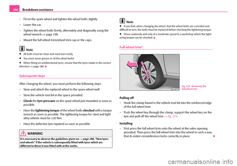
Full wheel trim*
Pulling off
– Hook the clamp found in the vehicle tool kit into the reinforced edge
of the full wheel trim.
– Push the wheel key through the clamp, support the wheel key on the
tyre and pull off the wheel trim ⇒fig. 159.
Installing
– First press the full wheel trim onto the wheel at the valve opening
provided. Then press the full wheel trim into the wheel in such a way
that its entire circumference locks correctly in place.
Fig. 159 Removing the full wheel trim
NKO A05F 20 MR08.book Page 196 Thursday, April 19, 2007 11:34 AM
Page 200 of 242

Breakdown assistance199
Using the systemSafetyDriving TipsGeneral MaintenanceBreakdown assistanceTechnical Data
surface or use a wide and stable base. Use a non-slip base (e.g. a rubber foot mat) if the surface is smooth, such as cobbled stones, a tiled floor, etc.
WARNING
•Always raise the vehicle with the doors closed - risk of injury.
•Take suitable measures to prevent the base of the lifting jack from slip- ping off - risk of injury!
•Place the lifting jack only on a solid and even surface.
•Not positioning the lifting jack at the specified points can result in damage to the vehicle. The ja ck can also slip off if it does not have sufficient grip - risk of injury!
•Never start the engine if the vehicl e is lifted - risk of accident.
•Never lie under the vehicle if the vehicle is only lifted with the vehicle lifting jack.
•It is important to support the vehicle with suitable supporting blocks if you wish to work under the lifted vehicle - risk of injury!
Securing wheels against being stolen*
You need a special adapter for sl ackening the safety wheel bolts.
– Pull off the full wheel trim/cap from the wheel hub or cap from the
safety wheel bolt.
– Insert the adapter with its toothed side fully into the inner toothing
of the safety wheel bolt right down in such a way that only the
outer hexagon is jutting out ⇒fig. 164.
– Insert the wheel wrench fully onto the adapter .
– Slacken the wheel bolt, or tighten it firmly ⇒page 198.
– Reinstall the full wheel trim/wheel cap after removing the adapter or
place the cap onto th e safety wheel bolt.
– Have the tightening torque checked with a torque wrench as soon as
possible. Steel and light alloy wheels must be tightened to a tightening
torque of 120 Nm.
The safety wheel bolts on vehicles fitted with them (one safety wheel bolt per wheel) can only be loosened or tighten up by using the adapter provided.
It is meaningful to note the code number hammered into the rear side of the adapter or the rear side of the safety wheel bolts. You can obtain a replacement adapter from a Škoda Service Partner, if necessary, by quoting this number.
We recommend that you always carry the adapter for the wheel bolts with you in the vehicle. It should be stowed in the vehicle tool kit.
Caution
•Damage can occur to the adapter and safety wheel bolt if the safety wheel bolt is tightened up too much.
•On steel wheels, the theft-deterrent wheel bolt must always be installed in the hole, which is close to the valve. Otherwise the full wheel trim cannot be mounted and the full wheel trim can be damaged during the assembly.
Note
The set of safety wheel bolts can be obtained from a Škoda Service Partner.
Fig. 164 Safety wheel bolt with adapter
AB
AA
AB
NKO A05F 20 MR08.book Page 199 Thursday, April 19, 2007 11:34 AM