service SKODA FABIA 2008 2.G / 5J Workshop Manual
[x] Cancel search | Manufacturer: SKODA, Model Year: 2008, Model line: FABIA, Model: SKODA FABIA 2008 2.G / 5JPages: 252, PDF Size: 40.88 MB
Page 209 of 252
Breakdown assistance208
Jump-starting
Initial steps
You can use the battery of another vehicle for jump-starting yours if the engine does not start because the battery on your vehicle is flat. You will require jump-start cables for this purpose.
Both batteries must have a rated voltage of 12 V. The capacity (Ah) of the battery supplying the power must not be significantly less than the capacity of the discharged battery in your vehicle.
Jump-start cables
Only use jump-start cables which have an adequately large cross-section and insu-lated terminal clamps. Please pay attention to the manufacturer's instructions.
Positive cable - colour coding in the majority of cases red.
Negative cable - colour coding in the majority of cases black.
WARNING
•A discharged battery may already freeze at temperatures just below 0°C. In case of frozen battery carry out no jump-starting - risk of explosion! Also after thawing of the battery there is a risk of caustic burns due to leaking acid. Replace the frozen battery.
•Please pay attention to the warning instructions relating to working in the engine compartment ⇒page 181.
Note
•There must not be any contact between the two vehicles otherwise current may flow as soon as the negative terminals are connected.
•The discharged battery must be properly connected to the system of the vehicle.
•Switch off any installed telephone and also pay attention to the instructions for use of the telephone in such a situation.
•We recommend purchasing jump-start cables from Škoda Service Partners as a Škoda original accessory or from retailers who sell branded batteries.
Start engine
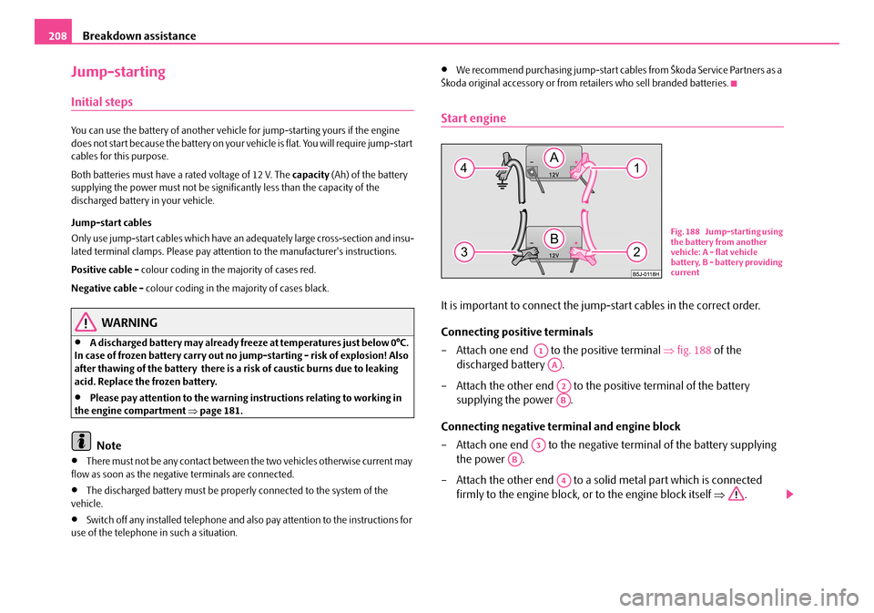
It is important to connect the jump-start cables in the correct order.
Connecting positive terminals
– Attach one end to the positive terminal ⇒fig. 188 of the
discharged battery .
– Attach the other end to the positive terminal of the battery
supplying the power .
Connecting negative terminal and engine block
– Attach one end to the negative terminal of the battery supplying
the power .
– Attach the other end to a solid metal part which is connected
firmly to the engine block, or to the engine block itself ⇒.
Fig. 188 Jump-starting using the battery from another vehicle: A - flat vehicle battery, B - battery providing current
A1
AA
A2
AB
A3
AB
A4
NKO A05F 20.book Page 208 Wednesday, April 2, 2008 1:02 PM
Page 212 of 252

Breakdown assistance211
Using the systemSafetyDriving TipsGeneral MaintenanceBreakdown assistanceTechnical Data
Rear towing eye
The rear towing eye is located below the rear bumper on the right ⇒fig. 191.
Tow-starting a vehicle
If the engine does not start, we generally do not recommend to tow-start
your vehicle. One should attempt to start the engine using jump start
cables ⇒page 208 or call on the services of the SERVICE mobile.
If your vehicle has to be towed:
– Engage 2nd or 3rd gear with the vehicle stationary.
– Depress the clutch pedal fully and keep it depressed.
– Switch on the ignition.
– Wait until both vehicles are moving then release the clutch pedal
slowly.
– Depress the clutch pedal fully when the engine fires and take the
vehicle out of gear.
WARNING
There is high risk of having an accident when tow-starting a vehicle, when for example the towed vehicle runs into the towing vehicle.
Caution
Vehicles which are fitted with a catalytic converter should not be tow-started over a distance of more than 50 metres. Unburnt fuel may get into the catalytic converter and damage it.
Towing in a vehicle fitted with a manual gearbox
Please refer to the notes ⇒page 209.
The car can be towed in with a tow bar or a tow rope or with the front or rear wheels raised. The maximum towing speed is 50 km/h.
Towing of a vehicle with an automatic gearbox
Please refer to the notes ⇒page 209.
The car can be towed in with a tow bar or a tow rope. Refer at the same time to the following guidelines:
•Move selector lever into N.
•The maximum towing speed is 50 km/h.
•The maximum permissible towing distance is 50 km. The gear oil pump does not operate when the engine is not running; the gearbox would not be adequately lubricated at higher speeds and over longer towing distance.
Caution
If the vehicle is towed in by a recovery vehicle, it should only be towed in with the front wheels raised. If the vehicle is raised at rear, the automatic gearbox is damaged!
Fig. 191 Rear towing eye
NKO A05F 20.book Page 211 Wednesday, April 2, 2008 1:02 PM
Page 214 of 252

Fuses and light bulbs213
Using the systemSafetyDriving TipsGeneral MaintenanceBreakdown assistanceTechnical Data
Fuses and light bulbs
Electric fuses
Replacing fuses in the dash panel
Defect fuses must be replaced.
Individual electrical circuits are protected by fuses. The fuses are located
on the left side of the dash panel behind the safety cover.
– Switch the ignition off and also the electrical component affected.
– Carefully swivel the cover in the direction of arrow and pull it out
⇒fig. 192.
– Find out which fuse belongs to the component which is not operating
⇒page 214, “Fuse assignment in the dash panel”.
– Take the plastic clip out of its fixture in the fuse cover, insert it onto the
respective fuse and pull out this fuse.
– Defect fuses can be detected by their melted metal strips. Replace the
defect fuse by a new fuse of the same ampere number.
– Insert the fuse cover into the dash panel in such a way that the guide
lugs are guided into the openings of the dash panel and then lock
them by pressing.
We recommend that you carry the box of replacement fuses with you which was delivered in your vehicle. You can obtain replacement fuses 8) from a Škoda Service Par tner.
Colour coding of fuses
Caution
•Never attempt to “repair” fuses and also do not replace them with a fuse of a higher amperage - risk of fire! This may also cause damage at another part of the electrical system.
•Have the electrical system checked as quickly as possible by a specialist garage if a newly inserted fuse blows again after a short time.
Fig. 192 Bottom side of the dash panel: fuse cover
8)Replacement fuses are, on the other hand, part of the basic equipping of the vehicle in somecountries.
ColourMaximum amperage
light brown5
brown7,5
red10
blue15
yellow20
white25
green30
NKO A05F 20.book Page 213 Wednesday, April 2, 2008 1:02 PM
Page 218 of 252
Fuses and light bulbs217
Using the systemSafetyDriving TipsGeneral MaintenanceBreakdown assistanceTechnical Data
Bulbs
Replacing bulbs
The relevant lamp must always be switched off before a light bulb is replaced.
Do not take hold of the glass bulb with naked fingers (even the smallest amount of dirt reduces the working life of the light bulb). Use a clean cloth, serviette or some-thing similar.
Defect light bulbs should only be replaced with light bulbs of the same type. The designation is located on the light socket or the glass bulb.
Changing certain bulbs is not something which you can do yourself, but requires to be done by a specialist. Other parts of the vehicle must be removed in order to change the light bulbs. This applies, in particular, to bulbs which can only be reached from the engine compartment.
We therefore recommend that you have any bulbs changed by a Škoda Service Partner or, in exceptional cases, by calling on other professional assistance.
Please note that the engine compartment is a hazardous area ⇒page 181, “Working in the engine compartment”.
We recommend that you carry the set of light bulbs with you which was delivered in your vehicle. Replacement light bulbs 9) are available at a Škoda Service Partner.
The set of light bulbs can be stowed in the locable box in the spare wheel.
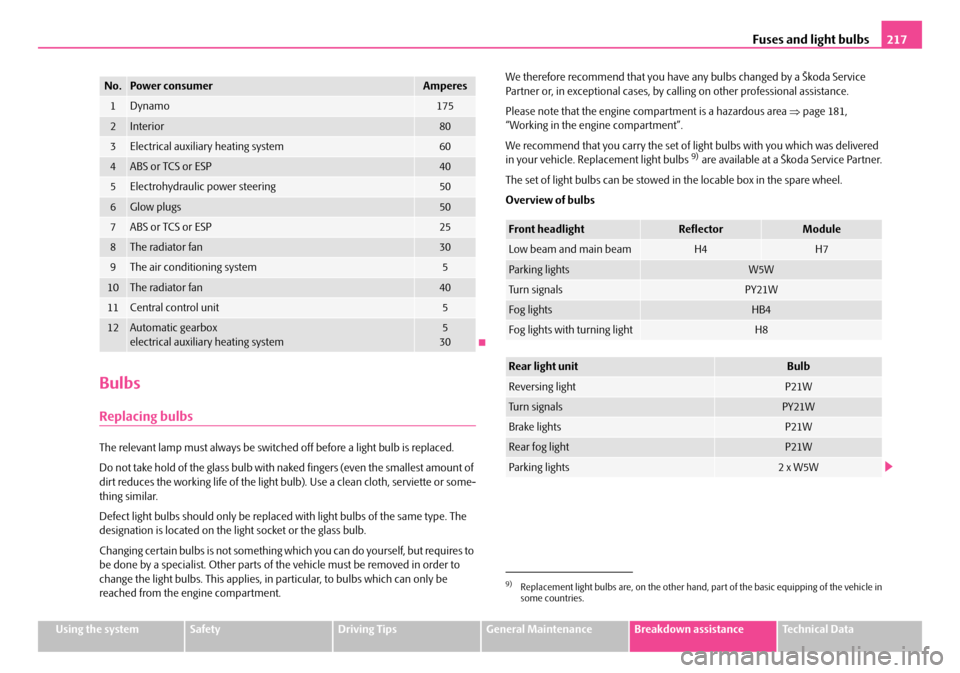
Overview of bulbs
No.Power consumerAmperes
1Dynamo175
2Interior80
3Electrical auxiliary heating system60
4ABS or TCS or ESP40
5Electrohydraulic power steering50
6Glow plugs50
7ABS or TCS or ESP25
8The radiator fan30
9The air conditioning system5
10The radiator fan40
11Central control unit5
12Automatic gearboxelectrical auxiliary heating system530
9)Replacement light bulbs are, on the other hand, part of the basic equipping of the vehicle insome countries.
Front headlightReflectorModule
Low beam and main beamH4H7
Parking lightsW5W
Tu r n s i g n a l sPY21W
Fog lightsHB4
Fog lights with turning lightH8
Rear light unitBulb
Reversing lightP21W
Tu r n s i g n a l sPY21W
Brake lightsP21W
Rear fog lightP21W
Parking lights2 x W5W
NKO A05F 20.book Page 217 Wednesday, April 2, 2008 1:02 PM
Page 220 of 252
Fuses and light bulbs219
Using the systemSafetyDriving TipsGeneral MaintenanceBreakdown assistanceTechnical Data
Switching on the low beam and main beam
– Open the bonnet.
– Remove the protective cap ⇒page 218, fig. 198.
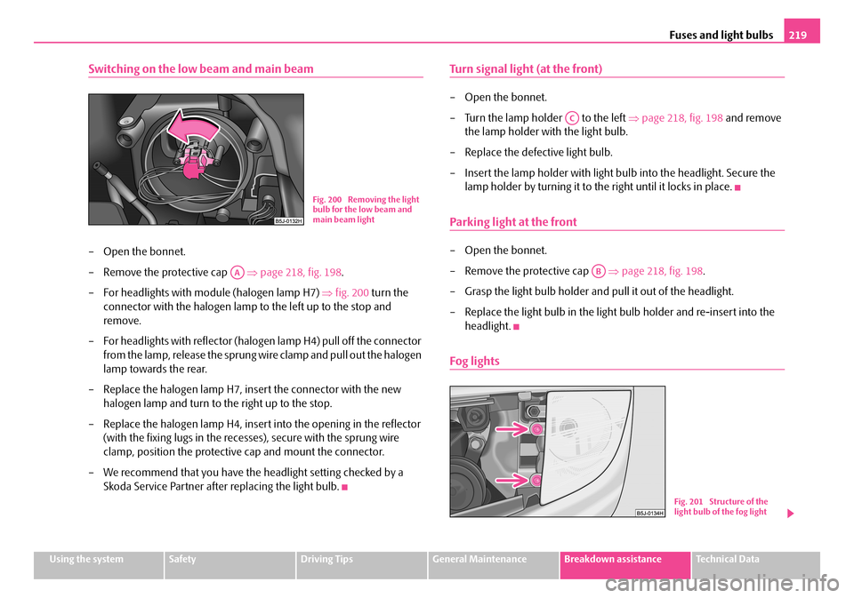
– For headlights with module (halogen lamp H7) ⇒fig. 200 turn the
connector with the halogen lamp to the left up to the stop and
remove.
– For headlights with reflector (halogen lamp H4) pull off the connector
from the lamp, release the sprung wire clamp and pull out the halogen
lamp towards the rear.
– Replace the halogen lamp H7, insert the connector with the new
halogen lamp and turn to the right up to the stop.
– Replace the halogen lamp H4, insert into the opening in the reflector
(with the fixing lugs in the recesses), secure with the sprung wire
clamp, position the protective cap and mount the connector.
– We recommend that you have the headlight setting checked by a
Skoda Service Partner after replacing the light bulb.
Turn signal light (at the front)
– Open the bonnet.
– Turn the lamp holder to the left ⇒page 218, fig. 198 and remove
the lamp holder with the light bulb.
– Replace the defective light bulb.
– Insert the lamp holder with light bulb into the headlight. Secure the
lamp holder by turning it to the right until it locks in place.
Parking light at the front
– Open the bonnet.
– Remove the protective cap ⇒page 218, fig. 198.
– Grasp the light bulb holder and pull it out of the headlight.
– Replace the light bulb in the light bulb holder and re-insert into the
headlight.
Fog lights
Fig. 200 Removing the light bulb for the low beam and main beam light
AA
AC
AB
Fig. 201 Structure of the light bulb of the fog light
NKO A05F 20.book Page 219 Wednesday, April 2, 2008 1:02 PM
Page 221 of 252
Fuses and light bulbs220
– Remove the grille next to the fog light (for turning light) or the grille
around the round fog light (for fog light) ⇒page 210.
– Release the screws ⇒page 219, fig. 201 and remove the fog light.
– Turn the connector with the light bulb up to the stop towards the left
and remove.
– Change the light bulb, put the connector back into the headlight and
secure by turning to the right.
– Put the fog light in place with the catch on the side opposite the grille
and then press in the opposite part. Applies to turning light, for round
fog light screw in the 3 screws.
– Screw in the screws ⇒page 219, fig. 201 and re-insert the grille
⇒page 210.
Storage compartment lighting*
We recommend having the light bulb replaced by a Škoda Service Partner.
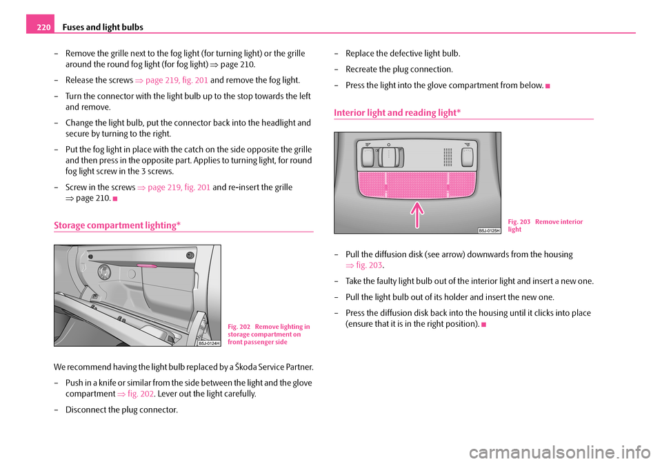
– Push in a knife or similar from the side between the light and the glove
compartment ⇒fig. 202. Lever out the light carefully.
– Disconnect the plug connector.
– Replace the defective light bulb.
– Recreate the plug connection.
– Press the light into the glove compartment from below.
Interior light and reading light*
– Pull the diffusion disk (see arrow) downwards from the housing
⇒fig. 203.
– Take the faulty light bulb out of the interior light and insert a new one.
– Pull the light bulb out of its holder and insert the new one.
– Press the diffusion disk back into the housing until it clicks into place
(ensure that it is in the right position).Fig. 202 Remove lighting in storage compartment on front passenger side
Fig. 203 Remove interior light
NKO A05F 20.book Page 220 Wednesday, April 2, 2008 1:02 PM
Page 224 of 252
Technical Data223
Using the systemSafetyDriving TipsGeneral MaintenanceBreakdown assistanceTechnical Data
Technical Data
Technical Data
General information
The details given in the official vehicle registration documents always take prece-dence over the details in the Owner's Manual. Please refer to the official vehicle registration documents or consult your Škoda Service Partner concerning the engine with which your vehicle is equipped.
Used abbreviations
Performances
The listed performance values were determined without performance-reducing equipment, e.g. air conditioning system.
Weight
The loading capacity is reduced in line with the range of the special equipment. The unloaden weight contains a fuel tank topped up to 90%. A driver with a weight of 75 kg is also included in the value.
Identification details
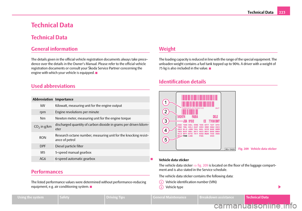
Vehicle data sticker
The vehicle data sticker ⇒fig. 209 is located on the floor of the luggage compart-ment and is also stated in the Service schedule.
The vehicle data sticker contains the following data:
Vehicle identification number (VIN)
Vehicle type
AbbreviationImportance
kWKilowatt, measuring unit for the engine output
rpmEngine revolutions per minute
NmNewton meter, measuring unit for the engine torque
CO2 in g/kmdischarged quantity of carbon dioxide in grams per driven kilom-eter
RONResearch octane number, measuring unit for the knocking resist-ance of petrol
DPFDiesel particle filter
M55-speed manual gearbox
AG66-speed automatic gearbox
Fig. 209 Vehicle data sticker
A1
A2
NKO A05F 20.book Page 223 Wednesday, April 2, 2008 1:02 PM
Page 248 of 252
Index247
Range . . . . . . . . . . . . . . . . . . . . . . . . . . . . . . . . . . . . . . . . 15
Rear fog light . . . . . . . . . . . . . . . . . . . . . . . . . . . . . . . . . . 47
Warning light . . . . . . . . . . . . . . . . . . . . . . . . . . . . . . 22
Rear mirror . . . . . . . . . . . . . . . . . . . . . . . . . . . . . . . . . . . 54
Rear seats . . . . . . . . . . . . . . . . . . . . . . . . . . . . . . . . . . . . 59
Rear window heater . . . . . . . . . . . . . . . . . . . . . . . . . . . 51
Recharge battery . . . . . . . . . . . . . . . . . . . . . . . . . . . . 191
Recirculated air mode
Air conditioning system . . . . . . . . . . . . . . . . . . . . 88
Heating . . . . . . . . . . . . . . . . . . . . . . . . . . . . . . . . . . . 84
Refuelling . . . . . . . . . . . . . . . . . . . . . . . . . . . . . . . . . . . 178
Remote control . . . . . . . . . . . . . . . . . . . . . . . . . . . . . . . 37
Synchronisation . . . . . . . . . . . . . . . . . . . . . . . . . . . 39
Replacing bulbs . . . . . . . . . . . . . . . . . . . . . . . . . . . . . 217
Replacing fuses . . . . . . . . . . . . . . . . . . . . . . . . . . . . . 213
Replacing the wiper blades . . . . . . . . . . . . . . . . . . . . . 53
Roof aerial . . . . . . . . . . . . . . . . . . . . . . . . . . . . . . . . . . 170
Running in the car . . . . . . . . . . . . . . . . . . . . . . . . . . . 159
S
Safe securing . . . . . . . . . . . . . . . . . . . . . . . . . . . . . . . . . 34
Safety . . . . . . . . . . . . . . . . . . . . . . . . . . . . . . . . . . . . . . 121
Safety information
Engine compartment . . . . . . . . . . . . . . . . . . . . . 181
Saving electrical energy . . . . . . . . . . . . . . . . . . . . . . 160
Seat belt height adjuster . . . . . . . . . . . . . . . . . . . . . 129
Seat belt warning light . . . . . . . . . . . . . . . . . . . . . . . 128
Seat belts . . . . . . . . . . . . . . . . . . . . . . . . . . . . . . . . . . . 126
Cleaning . . . . . . . . . . . . . . . . . . . . . . . . . . . . . . . . 175
fastening . . . . . . . . . . . . . . . . . . . . . . . . . . . . . . . . 128
Height adjustment . . . . . . . . . . . . . . . . . . . . . . . 129
Safety information . . . . . . . . . . . . . . . . . . . . . . . . 127
taking off . . . . . . . . . . . . . . . . . . . . . . . . . . . . . . . . 130
Warning light . . . . . . . . . . . . . . . . . . . . . . . . . . . . . . 29
Seats . . . . . . . . . . . . . . . . . . . . . . . . . . . . . . . . . . . . . . . . . 56
Heating . . . . . . . . . . . . . . . . . . . . . . . . . . . . . . . . . . . 58
Selector lever . . . . . . . . . . . . . . . . . . . . . . . . . . . . . . . . 103
Selector lever positions . . . . . . . . . . . . . . . . . . . . . . . 103
Service Display . . . . . . . . . . . . . . . . . . . . . . . . . . . . . . . 11
Service Interval Display . . . . . . . . . . . . . . . . . . . . . . . . 11
Setting temperature
Air conditioning system . . . . . . . . . . . . . . . . . . . . 86
Heating . . . . . . . . . . . . . . . . . . . . . . . . . . . . . . . . . . . 83
Setting the clock . . . . . . . . . . . . . . . . . . . . . . . . . . . . . . 13
Shifting . . . . . . . . . . . . . . . . . . . . . . . . . . . . . . . . . . . . . . . 97
Side airbag . . . . . . . . . . . . . . . . . . . . . . . . . . . . . . . . . . 136
Side lights . . . . . . . . . . . . . . . . . . . . . . . . . . . . . . . . . . . . 45
Snow chains . . . . . . . . . . . . . . . . . . . . . . . . . . . . . . . . . 198
Spare wheel . . . . . . . . . . . . . . . . . . . . . . . . . . . . . . . . . 202
Stability programme (ESP) . . . . . . . . . . . . . . . . . . . . 151
Starting the engine . . . . . . . . . . . . . . . . . . . . . . . . . . . . 95
Diesel engines . . . . . . . . . . . . . . . . . . . . . . . . . . . . 96
Petrol engines . . . . . . . . . . . . . . . . . . . . . . . . . . . . . 96
Steering force assistance . . . . . . . . . . . . . . . . . . . . . 156
Storage compartment
Lighting . . . . . . . . . . . . . . . . . . . . . . . . . . . . . . . . . . . 49
Storage compartments . . . . . . . . . . . . . . . . . . . . . . . . 77
Storage facilities . . . . . . . . . . . . . . . . . . . . . . . . . . . . . . 77
Sun visors . . . . . . . . . . . . . . . . . . . . . . . . . . . . . . . . . . . . 51
Switch in the driver door
Power windows . . . . . . . . . . . . . . . . . . . . . . . . . . . 40
Switching lights on and off . . . . . . . . . . . . . . . . . . . . . 45
Switching off the engine . . . . . . . . . . . . . . . . . . . . . . . 97
T
Tailgate
Lighting . . . . . . . . . . . . . . . . . . . . . . . . . . . . . . . . . . 50
Taking care of your vehicle . . . . . . . . . . . . . . . . . . . 169
TCS . . . . . . . . . . . . . . . . . . . . . . . . . . . . . . . . . . . . . . . . . 152
Warning light . . . . . . . . . . . . . . . . . . . . . . . . . . . . . 26
Telephone . . . . . . . . . . . . . . . . . . . . . . . . . . . . . . . . . . 109
Temperature
outside . . . . . . . . . . . . . . . . . . . . . . . . . . . . . . . . . . . 15
the first 1 500 kilometres . . . . . . . . . . . . . . . . . . . . . 159
The roof luggage rack system . . . . . . . . . . . . . . . . . . 73
Thickness of brake pads
Warning light . . . . . . . . . . . . . . . . . . . . . . . . . . . . . 25
Tilting roof . . . . . . . . . . . . . . . . . . . . . . . . . . . . . . . . . . . 43
Tiptronic . . . . . . . . . . . . . . . . . . . . . . . . . . . . . . . . . . . . 102
Tool . . . . . . . . . . . . . . . . . . . . . . . . . . . . . . . . . . . . . . . . 202
Towing a trailer . . . . . . . . . . . . . . . . . . . . . . . . . . . . . . 166
Towing eye
front . . . . . . . . . . . . . . . . . . . . . . . . . . . . . . . . . . . . 210
rear . . . . . . . . . . . . . . . . . . . . . . . . . . . . . . . . . . . . . 211
Towing protection monitoring . . . . . . . . . . . . . . . . . 40
towing vehicle . . . . . . . . . . . . . . . . . . . . . . . . . . . . . . . 209
Tow-starting . . . . . . . . . . . . . . . . . . . . . . . . . . . . . . . . 209
Tow-starting and towing vehicle
Automatic gearbox . . . . . . . . . . . . . . . . . . . . . . . 106
Traction control system (TCS) . . . . . . . . . . . . . . . . . 152
Warning light . . . . . . . . . . . . . . . . . . . . . . . . . . . . . 26
Trailer . . . . . . . . . . . . . . . . . . . . . . . . . . . . . . . . . . . . . . 166
General Maintenance . . . . . . . . . . . . . . . . . . . . 166
Transporting children safely . . . . . . . . . . . . . . . . . . 142
Tread depth . . . . . . . . . . . . . . . . . . . . . . . . . . . . . . . . . 195
NKO A05F 20.book Page 247 Wednesday, April 2, 2008 1:02 PM
Page 251 of 252

SIMPLY CLEVER
ŠkodaService
ŠkodaGenuine Parts
ŠkodaGenuine Accessories
05_08.indd 205_08.indd 220.3.2008 10:25:2520.3.2008 10:25:25