key SKODA FABIA 2010 2.G / 5J User Guide
[x] Cancel search | Manufacturer: SKODA, Model Year: 2010, Model line: FABIA, Model: SKODA FABIA 2010 2.G / 5JPages: 244, PDF Size: 29.53 MB
Page 42 of 244
Unlocking and locking
41
Using the system
Safety
Driving Tips
General Maintenance
Breakdown assistance
Technical Data
– Fold one of the outer rear seats forwards. – Move the operating lever with the aid of a
narrow object, e.g. a screwdriver, up to
the stop in the direction of arrow
page 40, fig. 30
and then unlock in the
direction of arrow .
– Open the boot lid from the outside.Remote control*DescriptionYou can use the remote control:
to unlock and lock the vehicle;
unlocking boot lid.
The transmitter with the battery is incorporat
ed in the handle of the master key. The
receiver is located in the interior of the car. The operating range of the remote control key is approx. 10 m. But this range can be reduced if the batteries are weak. The master key has a fold-open key bit which can be used for unlocking and locking the car manually and also for starting the engine. If a lost key is replaced or if the receiver unit has been repaired or a new unit installed, it is then necessary for a specialist garage to adapt the system. Only after this is it possible to again use the remote control.
Note
The remote control is automatically deactivated when the ignition is switched on.
The operation of the remote control may temporarily be affected by interference
from transmitters close to th
e car and which operate in the same frequency range (e.g.
mobile phone, TV transmitter).
The battery must be replaced if the centra
l locking or anti-theft alarm system does
not react to the remote control at less th
an 3 metres away. We recommend having the
battery replaced by
a specialist garage.
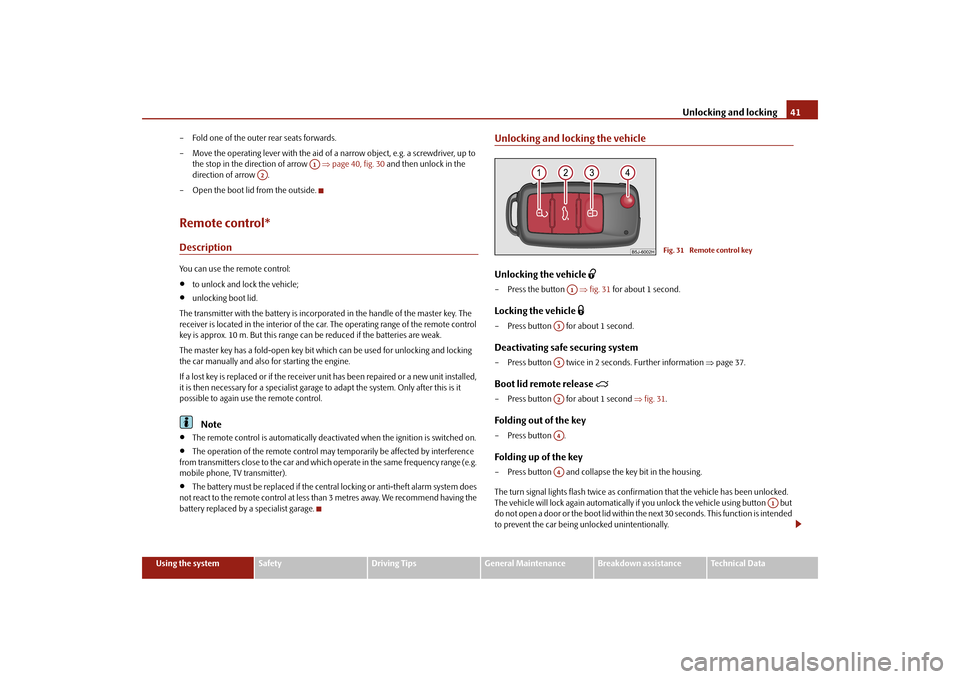
Unlocking and locking the vehicleUnlocking the vehicle
– Press the button
fig. 31
for about 1 second.
Locking the vehicle
– Press button for about 1 second.Deactivating safe securing system– Press button twice in 2 seconds. Further information
page 37.
Boot lid remote release
– Press button for about 1 second
fig. 31
.
Folding out of the key– Press button .Folding up of the key– Press button and collapse the key bit in the housing. The turn signal lights flash twice as confir
mation that the vehicl
e has been unlocked.
The vehicle will lock again automatically if
you unlock the vehicle using button but
do not open a door or the boot lid within th
e next 30 seconds. This
function is intended
to prevent the car being unlocked unintentionally.
A1
A2
Fig. 31 Remote control key
A1
A3A3A2A4A4
A1
s3j8.a.book Page 41 Tuesday, April 20, 2010 1:10 PM
Page 43 of 244
Unlocking and locking
42The safe securing system along with the anti-theft alarm system* are, however, deac- tivated during these 30 seconds. When the vehicle is unlocked or locked, the interior lights in the door contact are auto- matically switched on or off. Display of the locking The turn signal lights flash once to confir
m that the vehicle has been correctly locked.
If the vehicle is locked by pr
essing the button and some doors or the boot lid are
not closed, the turn signal lights flash only after closing.
WARNING
If the vehicle is locked from the outside and the safe securing system is acti-vated, there must not be any person in the vehicle as it is then not possible to open either a door or a window from the inside. The locked doors make it more difficult for rescuers to get into th
e vehicle in an emergency - hazard!
Note
Operate the radio remote control only when
the doors and boot lid are closed and
you have visual contact with the vehicle.
Once in the vehicle, you must not press the lock button
of the master key before
inserting the key into the ignition lock in
order to avoid the vehicle being inadvertently
locked and the anti-theft alarm system* being switched on. Should this happen, press the unlock button
of the master key.
Syncronisation of the remote controlIf the vehicle cannot be unlocked by actuatin
g the remote control system then it is
possible that the code in the key and the co
ntrol unit in the vehicle are no longer
synchronised. This can occur when the buttons on the radio-operated key are actuated a number of times outside of the operative
range of the equipment or the battery on
the remote control was replaced. This means it is necessary to
synchronise the code as follows:
press any button on the remote control;
pressing of the button means that the door will unlock with the key within 1
minute.Anti-theft alarm system*DescriptionThe anti-theft alarm system increases the level of protection against people seeking to break into the vehicle. The system triggers audible and visual warning signals if an attempt is made to break into the vehicle. How is the alarm
system activated?
The anti-theft alarm system is activated au
tomatically when the
unlocked vehicle is
locked with the key inserted in the driver's
door or with the remote control key. It is
activated 30 seconds after locking the door. How is the alarm system deactivated? The anti-theft alarm system is deactivated if
the vehicle is unlocked by only using the
radio remote control. The anti-theft alarm system is reactivated if the vehicle is not opened within 30 seconds after transmitting the radio signal. Once you unlock the vehicle by inserting the ke
y into the driver door you then have to
insert the key into the ignition lock and sw
itch the ignition on within 15 seconds after
opening the door in order to deactivate the anti-theft alarm system. The
alarm will be
triggered
if you do
not switch on
the ignition within 15 seconds.
When is the alarm triggered? The following security areas of
the locked vehicle are monitored:
bonnet;
boot lid;
doors;
ignition lock;
vehicle interior*
page 43;
Angle of the vehicle*
page 43;
Decoupling of the attached trailer;
A3
s3j8.a.book Page 42 Tuesday, April 20, 2010 1:10 PM
Page 44 of 244
Unlocking and locking
43
Using the system
Safety
Driving Tips
General Maintenance
Breakdown assistance
Technical Data
A drop in voltage of the on-board power supply.
An alarm is immediately triggered if either of the two battery terminals is disconnected while the anti-theft alarm system is activated. How is the alarm switched off? You switch the alarm off if you unlock the vehi
cle with the radio remote control or if you
switch the ignition on.
Note
The working life of the alarm siren is 5 years. More detailed information is available
by a specialist garage.
Before leaving the car, check that all the doors, windows and the electric
sliding/tilting roof* are properly closed in order to ensure that the anti-theft alarm system is fully operational.
Coding of the radio remote control and th
e receiver unit precludes the use of the
radio remote control from other vehicles.Interior monitor* and Towi
ng protection monitoring*
The interior monitor and the towing protection monitoring detect movements inside the vehicle interior and then trigger the alarm.The interior monitor and the towing protec
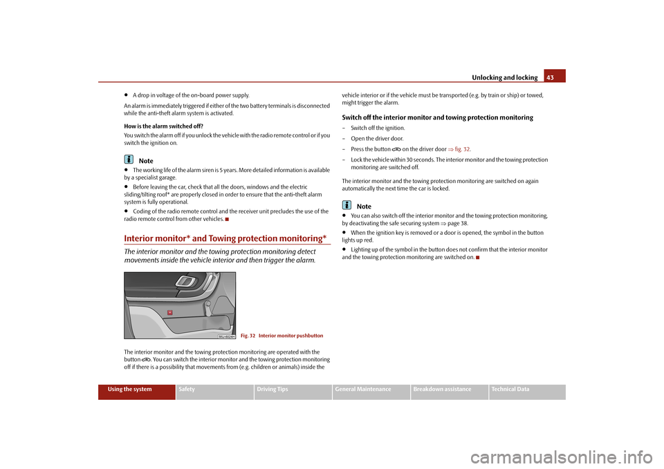
tion monitoring are operated with the
button
. You can switch the interior monitor
and the towing protection monitoring
off if there is a possibility that movements from (e.g. children or animals) inside the
vehicle interior or if the vehi
cle must be transported (e.g. by train or ship) or towed,
might trigger the alarm.Switch off the interior monitor and towing protection monitoring– Switch off the ignition. – Open the driver door.– Press the button
on the driver door
fig. 32
.
– Lock the vehicle within 30 seconds. The in
terior monitor and the towing protection
monitoring are switched off.
The interior monitor and the towing protec
tion monitoring are switched on again
automatically the next ti
me the car is locked.
Note
You can also switch off the interior moni
tor and the towing protection monitoring,
by deactivating the sa
fe securing system
page 38.
When the ignition key is removed or a door is opened, the symbol in the button
lights up red.
Lighting up of the symbol in the button
does not confirm that the interior monitor
and the towing protection mo
nitoring are switched on.
Fig. 32 Interior monitor pushbutton
s3j8.a.book Page 43 Tuesday, April 20, 2010 1:10 PM
Page 46 of 244
Unlocking and locking
45
Using the system
Safety
Driving Tips
General Maintenance
Breakdown assistance
Technical Data
After switching the ignition off, it is still possible to open or close the windows for a
further 10 minutes. The power windows are
switched off completely once you open
the driver or front passenger door.
When driving always use the existing he
ating, air conditioning and ventilation
system for ventilating the interior of the vehicle. If the windows are opened, dust as well as other dirt can get into the vehicle
and in addition the wind noise is more at
certain speeds.Force limiter of the power windowsThe electrically operated power windows are fitted with a force limiter. It reduces the risk of bruises or injuries when closing the windows. If there is an obstacle, the closing process is stopped and the window goes down by several centimeters. If the obstacle prevents the window from being closed during the next 10 seconds, the closing process is interrupted once agai
n and the window goes down by several
centimeters. You must try to close the window once agai
n within 10 seconds after the window has
gone down twice, even if the obstacle was not yet removed, the closing process is stopped. During this time it is not poss
ible to automatically
close the window. The
force limiter is still switched on. The force limiter is only switched off, if yo
u attempt to close the window within the next
10 seconds -
the window closes now with full strength!
If you wait longer than 10 seconds, the force limiter is switched on again.
WARNING
You should take particular care when closing the windows! You may otherwise suffer severe injuries as a result of getting an arm, for example, jammed in the window!Window convenience operationYou can open and close the electrically po
wered windows as follows when unlocking
and locking the vehicle (only close the sliding/tilting roof):
Opening a window– Hold the key in the locking cylinder of the
driver's door in the
unlock position or
press the unlock button of the radio re
mote control until all the windows are
opened.
Closing a window– Hold the key in the locking cylinder of the driver's door in the lock position or press
the lock button of the radio remote co
ntrol until all the windows are closed.
You can interrupt the opening or closing
operation of the windows immediately by
releasing the key or the lock button.
WARNING
The system is fitted with a force limiter
page 45. If there is an obstacle, the
closing process is stopped and the window goes down by several centimeters. You should then take particular care when closing the windows! You may otherwise suffer severe injuries as a re
sult of getting an arm, for example,
jammed in the window!Operational faultsElectrically operated powe
r windows do not operate
If the battery of the car has been disconnect
ed and then reconnected, the electrically
operated power windows do not operate. Th
e system must be activated. Proceed as
follows in order to re-establish the function:
Switch on the ignition,
slightly pull on the upper edge of the rele
vant button and hold it until the window
is closed,
release the switch,
you must pull the respective switch again in upward direction for approx. 3
seconds.
s3j8.a.book Page 45 Tuesday, April 20, 2010 1:10 PM
Page 48 of 244
Unlocking and locking
47
Using the system
Safety
Driving Tips
General Maintenance
Breakdown assistance
Technical Data
ClosingSliding closed/closing the sliding/tilting roof– Turn the switch to position
page 46, fig. 34
.
Safety closing The sliding/tilting roof is fitted with a force limiter. The sliding/tilting roof stops and moves back several centimetres when it ca
nnot be closed because there is something
in the way (e.g. ice). You can close the sliding/tilting roof completely without force limiter by pressing the sw
itch to the position
page 46, fig. 34
at the front for as
long as it takes for the sliding/
tilting roof to close completely
.
WARNING
Close the sliding/tilting roof carefully - risk of injury!Convenience operationYou can also close an open sliding/tilting roof from the outside. – Hold the key in the locking cylinder of the dr
iver's door in the lo
ck position or press
the lock button of the remote control unt
il the sliding/tilting roof is closed.
The closing operation stops when one re
leases the key or the lock button.
Note
The force limiter also operates for convenience closing.
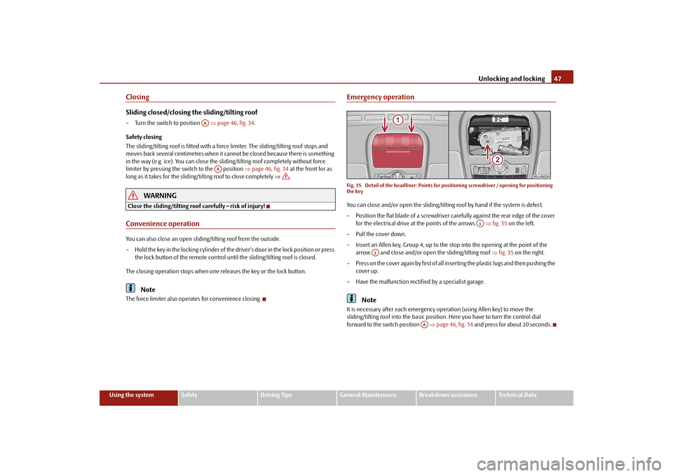
Emergency operationFig. 35 Detail of the headliner: Points for
positioning screwdriver / opening for positioning
the keyYou can close and/or open the sliding/tiltin
g roof by hand if the system is defect.
– Position the flat blade of a screwdriver carefully against the rear edge of the cover
for the electrical drive at the points of the arrows
fig. 35
on the left.
–Pull the cover down.– Insert an Allen key, Group 4, up to the stop into the opening at the point of the
arrow and close and/or open
the sliding/tilting roof
fig. 35
on the right.
– Press on the cover again by first of all in
serting the plastic lugs and then pushing the
cover up.
– Have the malfunction rectified by a specialist garage.
Note
It is necessary after each emergency op
eration (using Allen key) to move the
sliding/tilting roof into the basic position
. Here you have to tu
rn the control dial
forward to the switch position
page 46, fig. 34
and press for about 10 seconds.
AA
AA
A1
A2
AA
s3j8.a.book Page 47 Tuesday, April 20, 2010 1:10 PM
Page 49 of 244
Lights and Visibility
48Lights and VisibilityLightsSwitching lights on and off
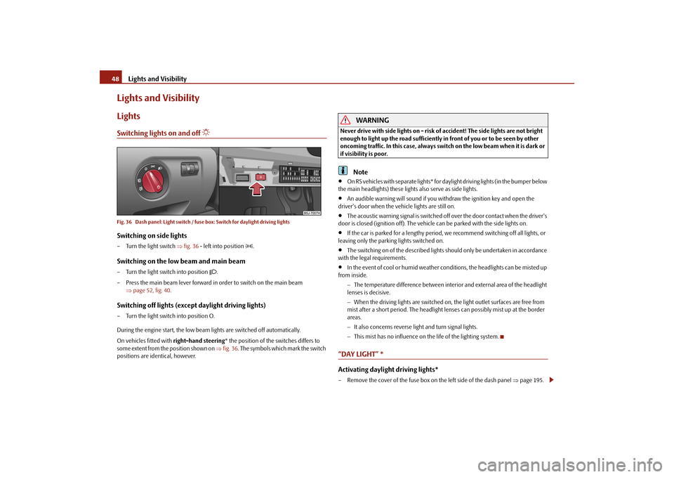
Fig. 36 Dash panel: Light switch / fuse box: Switch for daylight driving lightsSwitching on side lights– Turn the light switch
fig. 36
- left into position
.
Switching on the low beam and main beam– Turn the light switch into position
.
– Press the main beam lever forward in order to switch on the main beam
page 52, fig. 40
.
Switching off lights (except daylight driving lights)– Turn the light switch into position O. During the engine start, the low beam
lights are switched off automatically.
On vehicles fitted with
right-hand steering
* the position of the switches differs to
some extent from the position shown on
fig. 36
. The symbols which mark the switch
positions are identical, however.
WARNING
Never drive with side lights on - risk of accident! The side lights are not bright enough to light up the road sufficiently in front of you or to be seen by other oncoming traffic. In this case, always switch on the low beam when it is dark or if visibility is poor.
Note
O n R S v e h i c l e s w i t h s e p a ra t e l i g h t s * f o r d a
ylight driving lights (in the bumper below
the main headlights) these lights also serve as side lights.
An audible warning will sound if you wi
thdraw the ignition key and open the
driver's door when the vehicle lights are still on.
The acoustic warning signal is switched off over the door contact when the driver's
door is closed (ignition off). The vehicle
can be parked with
the side lights on.
If the car is parked for a lengthy period,
we recommend switching off all lights, or
leaving only the parking lights switched on.
The switching on of the described lights
should only be undertaken in accordance
with the legal requirements.
In the event of cool or humid
weather conditions
, the headlights can be misted up
from inside.
The temperature difference between interior and external area of the headlight lenses is decisive. When the driving lights are switched on,
the light outlet surfaces are free from
mist after a short period. The headlight lens
es can possibly mist up at the border
areas. It also concerns reverse light and turn signal lights. This mist has no influence on th
e life of the lighting system.
“DAY LIGHT” *Activating daylight driving lights*– Remove the cover of the fuse box on
the left side of the dash panel
page 195.
s3j8.a.book Page 48 Tuesday, April 20, 2010 1:10 PM
Page 53 of 244
Lights and Visibility
52The turn signal
and main beam lever
The parking lights and headlight flas
her are also switched on and off
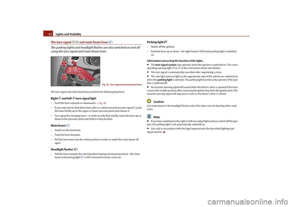
using the turn signal and main beam lever.The turn signal and main beam le
ver perform the following functions:
Right
and left
turn signal light
– Push the lever upwa
rds or downwards
fig. 40
.
– If you only wish to flash three times (the
so-called convenience turn signal*), push
the lever briefly up to the upper or lower pressure point and release it.
– Turn signal for changing lanes - in order to
only flash briefly, move the lever up or
down to the pressure point and hold it in this position.
Main beam
– Switch on the low beam. – Push the lever forwards.– Pull the lever back into the initial positi
on in order to switch the main beam off
again.
Headlight flasher
– Pull the lever towards the steering wheel (spring-tensioned position) - the main
beam and warning light
in the instrument cluster come on.
Parking light
– Switch off the ignition. – Push the lever up or down - the right-hand
or left-hand parking light is switched
on.
Information concerning the function of the lights.
The
turn signal system
only operates when the ignition is switched on. The corre-
sponding warning light
or in the instrument cluster also flashes.
The turn signal is automatically cancelled after negotiating a curve.
The side light and rear light on the appropriate side of the vehicle are switched on
when the
parking light
is selected. The parking light function only operates if the igni-
tion is switched off.
An acoustic warning signal will sound when
the driver's door is opened if the lever
is not in the middle position after removing the ignition key from the ignition lock. The acoustic warning signal will stop just as
soon as the driver's door is closed.
Caution
Use main beam or the headlight flasher only
if this does not risk dazzling other road
users.
Note
If you have switched on the right or left turn signal light and you switch off the igni-
tion, the parking light is no
t automatically switched on.
Use only in accordance with the legal
requirements the described lighting and
signal systems.
Fig. 40 Turn signal and main beam lever
s3j8.a.book Page 52 Tuesday, April 20, 2010 1:10 PM
Page 54 of 244
Lights and Visibility
53
Using the system
Safety
Driving Tips
General Maintenance
Breakdown assistance
Technical Data
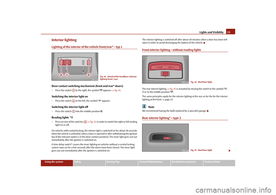
Interior lightingLighting of the interior of the vehicle front/rear* - typ 1Door contact switching mechanism (front and rear* doors)– Press the switch to the right, the symbol
appears
fig. 41
.
Switching the interior light on– Press the switch to the left, the symbol
appears.
Switching the interior light off– Press the switch into
the middle position
O.
Reading lights
– Press on one of the switches
fig. 41
in order to switch the right or left reading
light on or off.
On vehicles with central locking, the interi
or light is switched on for about 30 seconds
when the vehicle is unlocked, when a door is
opened or after withdrawing the ignition
key (if the relevant switch is in the door co
ntact position). The inner light goes out out
immediately after the ignition is switched on. A time delay switch* causes
the inner lighting on vehicl
es without a central locking
system stays on for a few seconds after the doors have been closed. The inner light goes out out immediately after the ignition is switched on.
The interior lighting is switched off after
about 10 minutes when a door has been left
open in order to avoid discharg
ing the battery of the vehicle.
Front interior lighting - without reading lightsThe rear interior lighting
fig. 42
is actuated by moving the switch to the symbol
,
O or to the middle position
.
The same principles apply for th
e interior lighting at the rear as for the for the interior
lighting at the front
page 53.
Note
We recommend having the bulb re
placed by a specialist garage.
Rear interior lighting* - type 2
Fig. 41 Detail of the headliner: Interior lighting front / rear
AAAAAA
AB
Fig. 42 Roof liner lightFig. 43 Roof liner light
s3j8.a.book Page 53 Tuesday, April 20, 2010 1:10 PM
Page 69 of 244
Seats and Storage
68 Remove carrier rails– Slacken the check points on the carrier rails using the vehicle key or a flat screw-
driver
page 67, fig. 63
.
– Grasp the carrier rail
at the position
page 67, fig. 63
and slacken it by
pulling in the direction of the arrow.
You can take out the removable storage
compartments* in order to facilitate the removal
page 78, “Removeable storage
compartments* in the luggage compartment”.
– Grasp the carrier rail at the position ,
slacken it by pulling in the direction of
the arrow and take it out.
– The carrier rail on the other side of
the luggage compartment can be removed in
the same way.
Install carrier rails– Position the carrier rails on the
sides of the luggage compartment.
– Press both check points on each carrier rail up to the stop.– Check the attachment of the
carrier rails by pulling it.
WARNING
Pay attention when installing that the ca
rrier rails and the variable loading floor
are correctly fixed, otherwise
the occupants are at risk.
Divide the luggage compartment with variable loading floor*
The luggage compartment can be divided with the variable loading floor. – Lift up the part with the holder and se
cure it by sliding it into the grooves
fig. 64
.
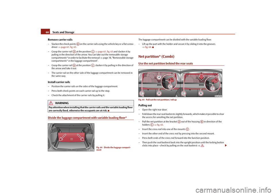
Net partition* (Combi)Use the net partition behind the rear seatsFig. 65 Pull out the net partition / roll upPulling out– Open the right rear door. – Fold down the rear seat backrests slightly forwards, which makes it possible to clear
the access for unrolling the net partition.
– Pull the net partition at the bracket out of the housing in direction of the
holders
fig. 65
.
– Insert the cross rod into one of the mounts .– Insert the other end of the cross rod by pressing into the second mount.– Press both ends of the cross rod
forward into the function position.
– Then push the seat backrest back into th
e upright position until the locking button
clicks into place - check by pulling on the seat backrest
.
AB
AA
A1
AA
A2
Fig. 64 Divide the luggage compart- ment
AA
AB
AC
AC
s3j8.a.book Page 68 Tuesday, April 20, 2010 1:10 PM
Page 76 of 244
Seats and Storage
75
Using the system
Safety
Driving Tips
General Maintenance
Breakdown assistance
Technical Data
WARNING
Take care when using the cigarette ligh
ter! Not paying proper attention or
incorrect use the cigarette lighter in
an uncontrolled manner may result in
burns.
The cigarette lighter and the power socket
also operates when the ignition is
switched off or the ignition key withdrawn. This is why you should never leave children unattended in the vehicle!
Caution
Always use matching
plugs to avoid damagi
ng the power socket.
Note
Connecting electrical components when
the engine is not running will drain
the battery of the vehicle - risk of battery draining!
Further information
page 184.
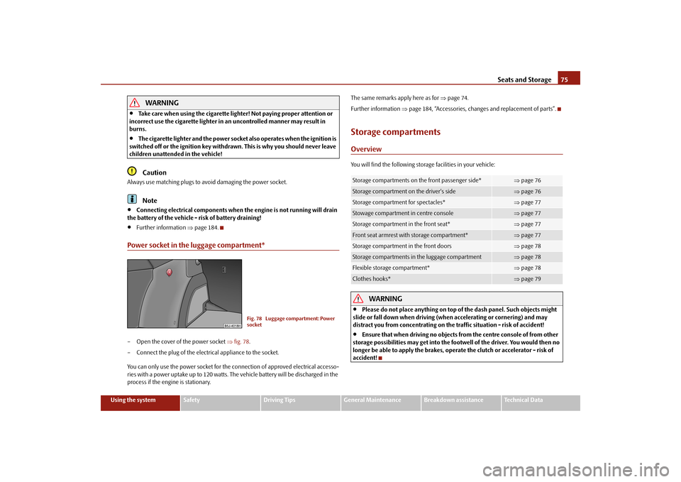
Power socket in the luggage compartment*– Open the cover of the power socket
fig. 78
.
– Connect the plug of the electr
ical appliance to the socket.
You can only use the power socket for the connection of approved electrical accesso- ries with a power uptake up to 120 watts. The vehicle battery will be discharged in the process if the engine is stationary.
The same remarks apply here as for
page 74.
Further information
page 184, “Accessories, changes and replacement of parts”.
Storage compartmentsOverviewYou will find the following storag
e facilities in your vehicle:
WARNING
Please do not place anything on top of the dash panel. Such objects might
slide or fall down when driving (whe
n accelerating or cornering) and may
distract you from concentrating on the traffic situation - risk of accident!
Ensure that when driving no objects from the centre console of from other
storage possibilities may get into the fo
otwell of the driver. You would then no
longer be able to apply the brakes, oper
ate the clutch or accelerator - risk of
accident!
Fig. 78 Luggage compartment: Power socket
Storage compartments on the front passenger side*
page 76
Storage compartment on the driver's side
page 76
Storage compartment for spectacles*
page 77
Stowage compartment in centre console
page 77
Storage compartment in the front seat*
page 77
Front seat armrest with storage compartment*
page 77
Storage compartment in the front doors
page 78
Storage compartments in the luggage compartment
page 78
Flexible storage compartment*
page 78
Clothes hooks*
page 79
s3j8.a.book Page 75 Tuesday, April 20, 2010 1:10 PM