SKODA FABIA 2010 2.G / 5J Technical Change
Manufacturer: SKODA, Model Year: 2010, Model line: FABIA, Model: SKODA FABIA 2010 2.G / 5JPages: 14, PDF Size: 0.63 MB
Page 1 of 14
ŠkodaFabia
ŠkodaRoomster
SUPPLEMENT TO THE OWNER'S MANUAL
Technical Changes 11/2010
Dodatek Návodu k obsluze
Fabia, Roomster anglicky 11.10
S00.5612.04.20
5J6 012 025 GN
SIMPLY CLEVER
Page 2 of 14
Introduction1
IntroductionThis supplement to the FABIA Owner's manual Edition 05.10 and the ROOMSTER
Owner's manual Edition 03.10, henceforth referred to as the Owner's manual.
The information given in this supplement takes preference over the information in the
Owner's manual.
Special equipment is marked with the symbol *.
We wish you a good journey
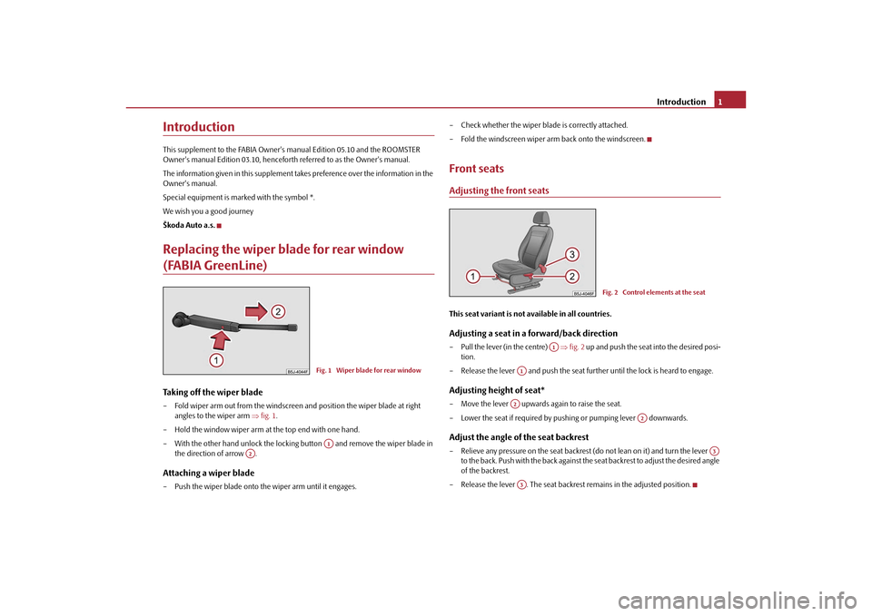
Škoda Auto a.s.Replacing the wiper blade for rear window (FABIA GreenLine)Taking off the wiper blade – Fold wiper arm out from the windscreen and position the wiper blade at right angles to the wiper arm fig. 1 .
– Hold the window wiper arm at the top end with one hand.
– With the other hand unlock the locking button and remove the wiper blade in the direction of arrow .Attaching a wiper blade– Push the wiper blade onto th e wiper arm until it engages. – Check whether the wiper blade is correctly attached.
– Fold the windscreen wiper ar
m back onto the windscreen.
Front seatsAdjusting the front seatsThis seat variant is not available in all countries.Adjusting a seat in a forward/back direction– Pull the lever (in the centre) fig. 2 up and push the seat into the desired posi-
tion.
– Release the lever and push the seat further until the lock is heard to engage.Adjusting height of seat*– Move the lever upwards again to raise the seat.
– Lower the seat if required by pushing or pumping lever downwards.Adjust the angle of the seat backrest– Relieve any pressure on the seat backrest (do not lean on it) and turn the lever
to the back. Push with the ba ck against the seat backrest to adjust the desired angle
of the backrest.
– Release the lever . The seat backrest remains in the adjusted position.
Fig. 1 Wiper blade for rear windowA1
A2
Fig. 2 Control elements at the seat
A1
A1A2
A2
A3
A3
s35k.1j.book Page 1 Thursday, September 16, 2010 1:02 PM
Page 3 of 14
“START - STOP”*
2
“START - STOP”*Messages in the instrument cluster display (valid for vehicles without MAXIDOT
info display*)
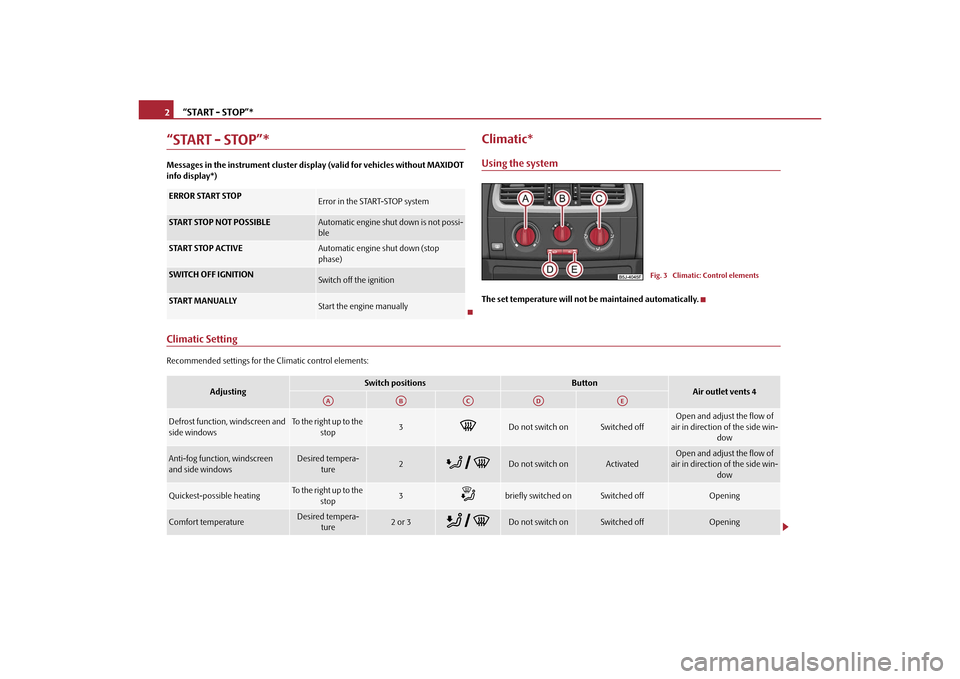
Climatic*Using the systemThe set temperature will not be maintained automatically.
Climatic SettingRecommended settings for the Climatic control elements:ERROR START STOP
Error in the START-STOP system
START STOP NOT POSSIBLE
Automatic engine shut down is not possi-
ble
START STOP ACTIVE
Automatic engine shut down (stop
phase)
SWITCH OFF IGNITION
Switch off the ignition
START MANUALLY
Start the engine manually
Fig. 3 Climatic: Control elements
Adjusting
Switch positions
Button
Air outlet vents 4
Defrost function, windscreen and
side windows
To the right up to the stop
3
Do not switch on
Switched off
Open and adjust the flow of
air in direction of the side win- dow
Anti-fog function, windscreen
and side windows
Desired tempera-
ture
2
Do not switch on
Activated
Open and adjust the flow of
air in direction of the side win-
dow
Quickest-possible heating
To the right up to the stop
3
briefly switched on
Switched off
Opening
Comfort temperature
Desired tempera-ture
2 or 3
Do not switch on
Switched off
Opening
AA
AB
AC
AD
AE
s35k.1j.book Page 2 Thursday, September 16, 2010 1:02 PM
Page 4 of 14
Electronic Differential Lock (EDL and XDS)*3
Electronic Differential Lock (EDL and XDS)*XDS function (Fabia RS and Fabia RS Combi only)
XDS is an extension to the electronic differential lock. XDS does not respond to traction,
but to the relief of the inner front wheel during fast cornering. XDS applies pressure to
the brake of the inner wheel to prevent it fr om spinning. Thus, the traction is improved
and the vehicle follows the desired track.Grades of petrolPrescribed types of fuel - unleaded petrol RON 98/95
Use unleaded petrol 98 RON. You can also use unleaded RON 95. However some loss
of power is to be expected when doing so.
If unleaded RON 98 or RON 95 is not available, you ca n refuel with unleaded RON 91
in an emergency. After refuelling, conti nue driving at medium engine speeds and
minimum engine load. Driving at high engine speeds or heavy engine loads can lead
to serious engine damage! Refuel with pe trol with the specified octane number as
often as possible.
Fuel with a lower octane number than RON 91 must not be used even in an emer-
gency. Otherwise you can ca use serious engine damage!
Tyre repair kit*General informationThe tyre repair kit is located in a box un der the carpet in the luggage compartment.
Use the tyre repair kit to re liably repair tyre damage ca used by foreign bodies or a
puncture with diameters up to 4 mm. Do no t remove foreign bodies, e.g. screws or
nails, from the tyre!
The repair can be undertaken on the vehicle immediately.
The repair with the tyre repair kit is not at all intended to replace a permanent repair
on the tyre, this repair only serves to reach the next specialist garage.
Do not use the tyre repair kit:•
to repair wheel damage,
•
in outside temperatures of less than -20 °C (-4 °F),
•
with tears or punctures greater than 4 mm in size,
•
to repair damage to the tyre wall,
•
when driving with very low tyre pressure or with a completely flat tyre,
•
if the use-by-date (see inflation bottle) has passed.
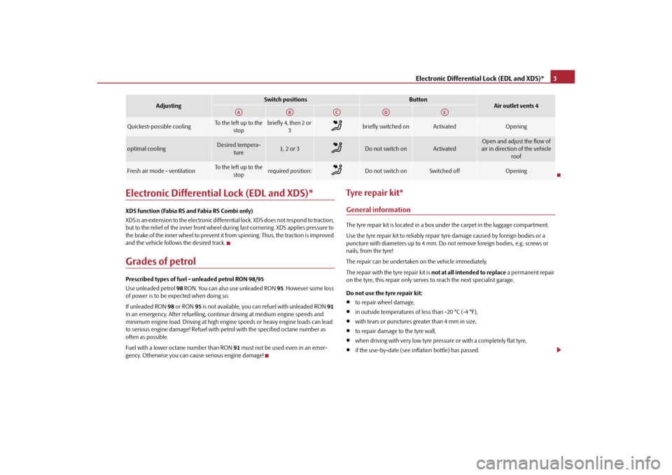
Quickest-possible cooling
To the left up to the
stop
briefly4, then 2or 3
briefly switched on
Activated
Opening
optimal cooling
Desired tempera-ture
1, 2 or 3
Do not switch on
Activated
Open and adjust the flow of
air in direction of the vehicle roof
Fresh air mode - ventilation
To the left up to the
stop
required position:
Do not switch on
Switched off
Opening
Adjusting
Switch positions
Button
Air outlet vents 4
AA
AB
AC
AD
AE
s35k.1j.book Page 3 Thursday, September 16, 2010 1:02 PM
Page 5 of 14
Tyre repair kit*
4WARNING
•
If you find yourself in flowing traffic switch on the hazard warning lights
system and place the warning triangle on the side of the road at the prescribed
distance from your vehicle. Comply with the national legal regulations. In this
way you are protecting not only yourself but also other road users.
•
Park the vehicle as far away as possible from the traffic flow. Park on as flat
and firm a surface as possible.
•
A tyre filled with sealant has the same driving characteristics as a standard
tyre.
•
Do not drive faster than 80 km/h, (50 mph).
•
Avoid accelerating at full throttle , sharp braking and fast cornering.
•
Check the tyre inflation pressure after driving 10 minutes.
•
Sealant is hazardous to heath. Remove immediately if it comes into contact
with the skin.For the sake of the environment
Used or aged sealant must be disposed of in accordance with environmental protec-
tion regulations.
Note
•
Observe the manufacturer's usage instructions for the tyre repair kit.
•
You can purchase a new bottle of sealant from the range of the Škoda original
accessories.
•
Change the wheel that was repaired using the tyre repair kit or consult a specialist
garage about possibilities for getting repairs done.
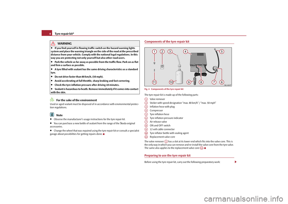
Components of the tyre repair kitFig. 4 Components of the tyre repair kitThe tyre repair kit is made up of the following parts:
Valve remover
Sticker with speed designation “max. 80 km/h” / “max. 50 mph”
Inflation hose with plug
Compressor
Tyre inflation hose
Tyre inflation pressure indicator
Air release valve
ON and OFF switch
12 volt cable connector
Tyre inflator bottle with sealing agent
Replacement valve core
The valve remover has a slot at its lower end which fits into the valve core. This is
the only way in which you can remove and re-i nstall the valve core from the tyre valve.
The same also applies to the replacement valve core .Preparing to use the tyre repair kitBefore using the tyre repair kit, carry out the following preparatory work:A1A2A3A4A5A6A7A8A9A10A11
A1
A11
s35k.1j.book Page 4 Thursday, September 16, 2010 1:02 PM
Page 6 of 14
Tyre repair kit*5
– Park the vehicle as far away as possible from the traffic flow. Park on as flat and firm
a surface as possible.
–Have all the occupants get out. While changing a wheel, the occupants of the
vehicle should not stand on the road (e.g. behind a crash barrier).
– Switch off the engine and engage 1st gear or if your vehicle is fitted with an auto-
matic gearbox, position the selector lever into position P .
– Apply the handbrake firmly.
– Check whether you can carry out the repairs with the tyre repair kit page 3,
“General information”.
– If a trailer is coupled, uncouple it.
– Remove the tyre repair kit from the luggage compartment.
– Stick the sticker page 4, fig. 4 on the dash panel in view of the driver.
– Do not remove the foreign body, e.g. screw or nail, from the tyre.
– Unscrew the valve cap.
– Use the valve remover to remove the va lve core and place it down on a clean
surface.Seal and inflate tyresSealing tyres– Forcefully shake the tyre inflator bottle page 4, fig. 4 several times.
– Firmly screw inflation hose onto the tyre inflator bottle in a clockwise direction . The film on the cap is pierced automatically.
– Remove the plug from the inflation hose and plug the open end fully into the tyre valve.
– Hold the bottle with the floor facing up wards and fill the whole sealing agent in
the tyre inflator bottle into the tyres.
– Remove the empty tyre inflator bottle from the valve.
– Screw the valve core back into the tyre valve using the valve remover .
Pumping up the tyres– Screw the tyre inflation hose page 4, fig. 4 of the air compressor firmly onto
the tyre valve.
– Check whether the air re lease valve is closed.
– Start the engine and run it in idle.
– Plug the cable connector into the 12 Vo lt socket in the vehicle, see Owner's
manual.
– Switch on the air compressor with the ON and OFF switch .
– Allow the air compressor to run until reac hing a pressure of 2.0 - 2.5 bars for a
maximum of 8 minutes !
– Switch off the air compressor.
– If you cannot reach an air pressure of 2.0 - 2.5 bar, unscrew the tyre inflation hose from the tyre valve.
– Drive the vehicle 10 metres forwards or backwards to allow the sealing agent to
distribute in the tyre.
– Screw the tyre inflation hose of the air compressor firmly back onto the tyre
valve and repeat the inflation procedure.
– If you cannot reach the required tyre inflation pressure here either, this means the tyre has sustained too much damage. You cannot seal with tyre with the break-
down kit .
– Switch off the air compressor.
– Remove the tyre inflation hose from the tyre valve.
If you reached a tyre inflation pressure of 2.0 - 2.5 bar, resume driving at a maximum
speed of 80 km/h (50 mph).
Check the tyre inflation pressure after driving 10 minutes page 6, “Check after
driving for 10 minutes”.
WARNING
•
During inflation, the tyre inflation hose and air compressor may get hot-
risk of injury!
A2
A1
A10
A3
A10
A3
A10
A1
A5
A7
A9
A8
A5
A5
A5
s35k.1j.book Page 5 Thursday, September 16, 2010 1:02 PM
Page 7 of 14
Tow-starting and towing vehicle
6
•
Do not place hot tyre inflation hoses or hot air compressors on flammable
materials - risk of fire!
•
If you cannot inflate the tyre to at least 2.0 bar, this means the damage
sustained was too serious. The sealing agent cannot be used to seal the tyre. Do
not drive the vehicle. Get professional assistance.Caution
Switch off the air compressor after running 8 minutes at the latest - danger of over-
heating! Allow the air compressor to cool a few moments before switching it on
again.Check after driving for 10 minutesCheck the tyre inflation pressu re after driving 10 minutes.If the tyre inflation pressure is 1.3 bar or less:–Do not drive the vehicle! You cannot properly seal wi th tyre with the breakdown
kit.
– Obtain professional assistance.If the tyre inflation pressure is 1.3 bar or more:– Adjust the tyre inflation pressure to the correct value (see inside of fuel filler cap).
– Continue driving carefully to the nearest specialist garage at a maximum speed of 80 km/h (50 mph).
Tow-starting and towing vehicleGeneral
Caution
Do not push or two the vehicle to start the engine - likely engine damage! In vehicles
with catalytic converters, fuel may get into the catalytic converter where it may ignite.
This results in the catalytic converter overheating and being destroyed. To help start
the engine, you can use a battery from another vehicle, see Owner's manual.Technical DataWeightThe indicated unloaded weight is for orient ation purposes only. It is for the basic
equipping of the vehicle not includin g special features or accessories.
Caution
Do not exceed the permissible overall weight of the vehicle - risk of accident and
damage to the vehicle.
WARNING (continued)
s35k.1j.book Page 6 Thursday, September 16, 2010 1:02 PM
Page 8 of 14
Technical Data7
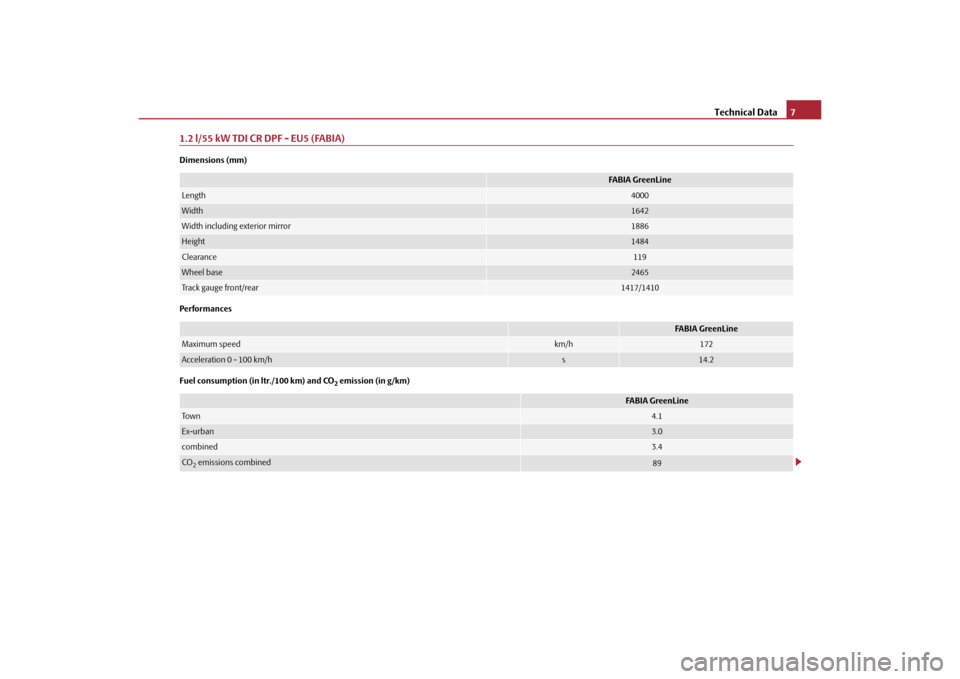
1.2 l/55 kW TDI CR DPF - EU5 (FABIA)Dimensions (mm)
Performances
Fuel consumption (in ltr./100 km) and CO
2 emission (in g/km)
FABIA GreenLine
Length
4000
Width
1642
Width including exterior mirror
1886
Height
1484
Clearance
119
Wheel base
2465
Track gauge front/rear
1417/1410
FABIA GreenLine
Maximum speed
km/h
172
Acceleration 0 - 100 km/h
s
14.2
FABIA GreenLine
To w n
4.1
Ex-urban
3.0
combined
3.4
CO2 emissions combined
89
s35k.1j.book Page 7 Thursday, September 16, 2010 1:02 PM
Page 9 of 14
Technical Data
8
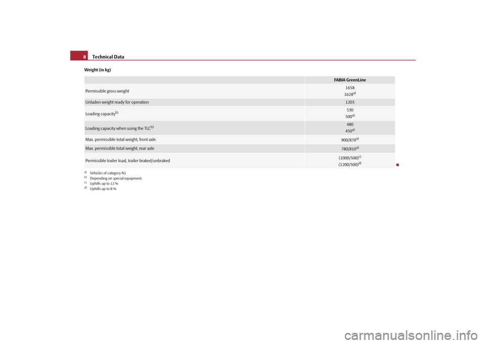
Weight (in kg)
FABIA GreenLine
Permissible gross weight
1658
1628
a)
a)Vehicles of category N1Unladen weight ready for operation
1203
Loading capacity
b)
b)Depending on special equipment.
530
500a)
Loading capacity when using the TLC
b)
480
450a)
Max. permissible total weight, front axle
900/870
a)
Max. permissible total weight, rear axle
780/810
a)
Permissible trailer load, trailer braked/unbraked
(1000/500)
c)
(1200/500)
d)
c)Uphills up to 12 %d)Uphills up to 8 %s35k.1j.book Page 8 Thursday, September 16, 2010 1:02 PM
Page 10 of 14
Technical Data9
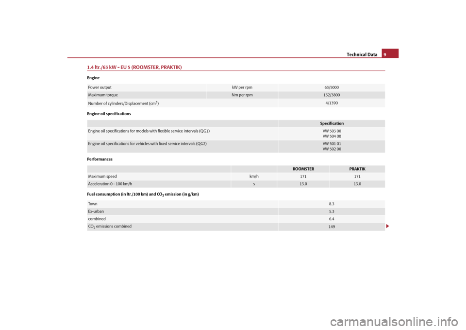
1.4 ltr./63 kW - EU 5 (ROOMSTER, PRAKTIK)Engine
Engine oil specifications
Performances
Fuel consumption (in ltr./100 km) and CO
2 emission (in g/km)
Power output
kW per rpm
63/5000
Maximum torque
Nm per rpm
132/3800
Number of cylinders/Displacement (cm
3)
4/1390
Specification
Engine oil specifications for models with flexible service intervals (QG1)
VW 503 00
VW 504 00
Engine oil specifications for vehicles with fixed service intervals (QG2)
VW 501 01
VW 502 00
ROOMSTER
PRAKTIK
Maximum speed
km/h
171
171
Acceleration 0 - 100 km/h
s
13.0
13.0
To w n
8.3
Ex-urban
5.3
combined
6.4
CO2 emissions combined
149
s35k.1j.book Page 9 Thursday, September 16, 2010 1:02 PM